

Sharp Air Conditioner AY-AP24CJ-AE-A24CJ Service Manual
What's Included?
Fast Download Speeds
Online & Offline Access
Access PDF Contents & Bookmarks
Full Search Facility
Print one or all pages of your manual
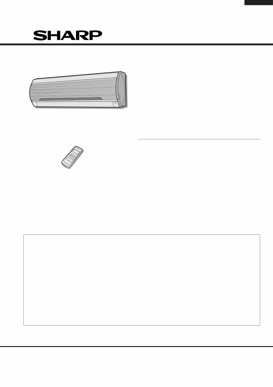
AY-AP18CJ
AY-AP24CJ
AE-A18CJ
AE-A24CJ
INDOOR UNIT
AY-AP18CJ
AY-AP24CJ
OUTDOOR UNIT
MODELS
SERVICE MANUAL
S0242AYAP24CJ
SHARP CORPORATION
In the interests of user-safety (Required by safety regulations in
some countries) the set should be restored to its original
condition and only parts identical to those specified should be
used.
SPLIT SYSTEM
ROOM AIR CONDITIONERS
AE-A18CJ
AE-A24CJ
TABLE OF CONTENTS
Page
SPECIFICATIONS ............................................................................................................................................. 2
EXTERNAL DIMENSIONS ............................................................................................................................... 3
WIRING DIAGRAMS ......................................................................................................................................... 4
ELECTRICAL PARTS ....................................................................................................................................... 6
MICROCOMPUTER CONTROL SYSTEM ....................................................................................................... 7
FUNCTIONS ................................................................................................................................................... 13
TROUBLESHOOTING GUIDE OF CONTROL CIRCUIT ................................................................................ 20
REFRIGERATION CYCLE .............................................................................................................................. 25
PERFORMANCE CURVES ............................................................................................................................ 27
REFRIGERANT PIPE INSTALLATION WORKS ............................................................................................. 28
DISASSEMBLING PROCEDURE ................................................................................................................... 29
REPLACEMENT PARTS LIST ........................................................................................................................ 39
AY-AP18CJ
AY-AP24CJ
AE-A18CJ
AE-A24CJ
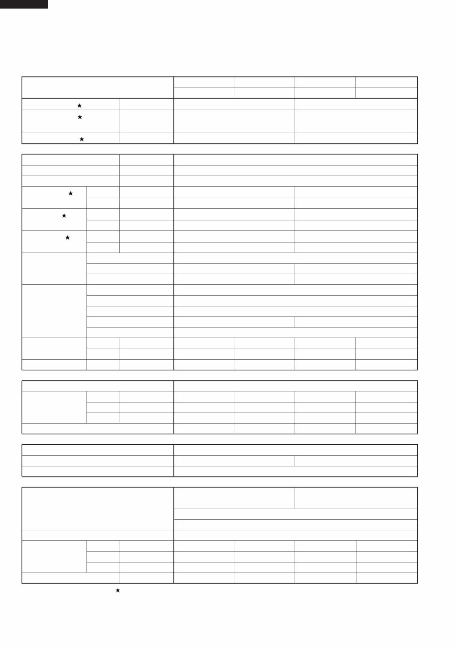
2
ITEMS INDOOR UNIT OUTDOOR UNIT INDOOR UNIT OUTDOOR UNIT
AY-AP18CJ AE-A18CJ AY-AP24CJ AE-A24CJ
Cooling capacity kW 5.0 6.5
Heating capacity kW 5.8 8.1
Moisture removal Liters/h 1.6 2.2
Electrical data
Phase – Single
Rated frequency Hz 50
Rated voltage V 230 – 240
Rated current Cool A 9.4 14.2
Heat A 8.6 14.6
Rated input Cool kW 2.17 3.00
Heat kW 1.98 3.09
Power factor Cool % 100 – 96 92 – 88
Heat % 100 – 96 92 – 88
Compressor Type Hermetically sealed rotary type
Model PH33VPET 2JS464D3AA02
Oil charge 900cc [DIAMOND MS32(N-1)] 1130cc (ATMOS M60 or SUNISO 4GD1D)
Refrigerant system Evaporator Louver fin and Grooved tube type
Condenser Corrgate fin and Grooved tube type
Control Capillary tube
Refrigerant volume 1380g 1820g
De-lce system Micro computer controled reverse sysetm
Noise level High dB(A) 40 52 44 54
(at cooling) Med. dB(A) 36 – 39 –
Low dB(A) 34 – 37 –
Fan system
Drive Direct drive
Air flow quantity High m
3
/min. 15.3 52 18.1 48
(at cooling) Med. m
3
/min. 13.4 – 15.0 –
Low m
3
/min. 11.3 – 13.7 –
Fan Cross flow fan Propeller fan Cross flow fan Propeller fan
Connections
Refrigerant coupling Flare type
Refrigerant tube size Gas, Liquid 1/2", 1/4" 5/8", 1/4"
Drain piping mm O.D ø 20
Others
Safety device Compressor: Internal protector Compressor: Internal protector
Fan motors: Thermal protector(Internal)
Fuse, Micro computer control
Air filters Polypropylene net (Washable)
Net dimensions Width mm 1040 (1155) 890 (1020) 1040 (1155) 890 (1020)
(Cartont dimensions) Height mm 325 (300) 645 (735) 325 (300) 645 (735)
Depth mm 220 (385) 327 (398) 220 (385) 327 (398)
Net weight (Gross weight) kg 16 (21) 58 (62) 16 (21) 64 (68)
Note: The condition of star ( ) marked item are “ AS/NZS3823.1.1 : 1998’ ”.
SPECIFICATIONS
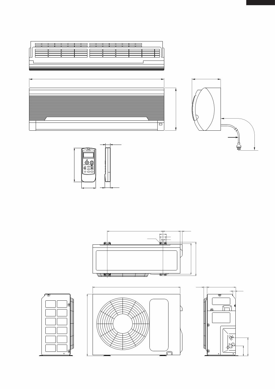
3
AY-AP18CJ
AY-AP24CJ
AE-A18CJ
AE-A24CJ
570
645
202
122
320
342
890 290 37
30
172
25
62
46.3
10.5
ø4.5
EXTERNAL DIMENSIONS
Figure E-1. INDOOR UNIT
Figure E-2. OUTDOOR UNIT
220
1750
Power supply cord
(AY-AP18CJ only)
[Length unit : mm] 325
1040
Remote controller
58
18.5
22
140
TEMP.
INVERTER AIR CONDITIONER
TEMP. MODE
FAN TIMER
AY-AP18CJ
AY-AP24CJ
AE-A18CJ
AE-A24CJ
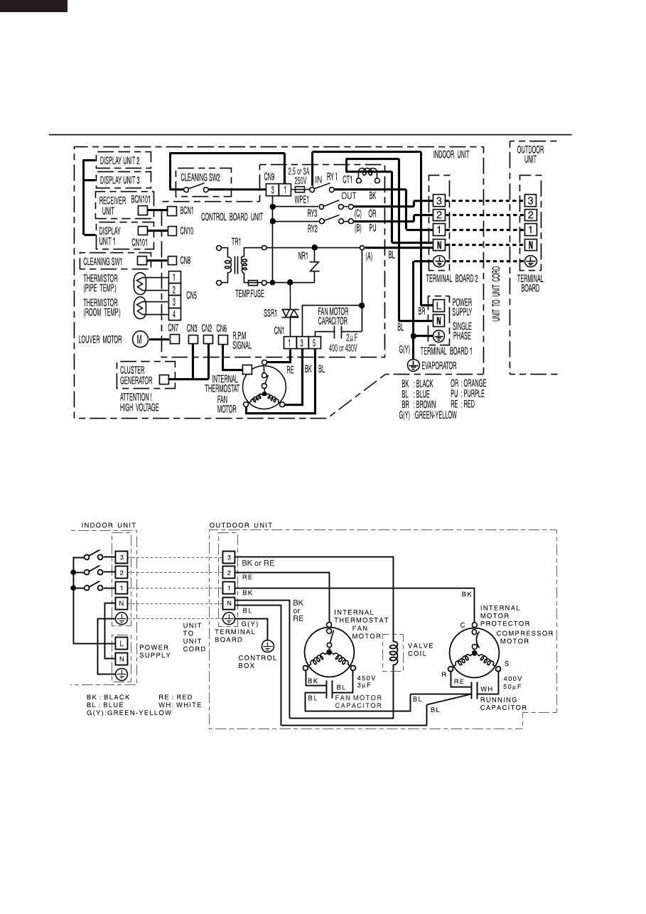
4
WIRING DIAGRAMS
Figure W-1. Wiring Diagram for AY-AP18CJ
Figure W-2. Wiring Diagram for AE-A18CJ
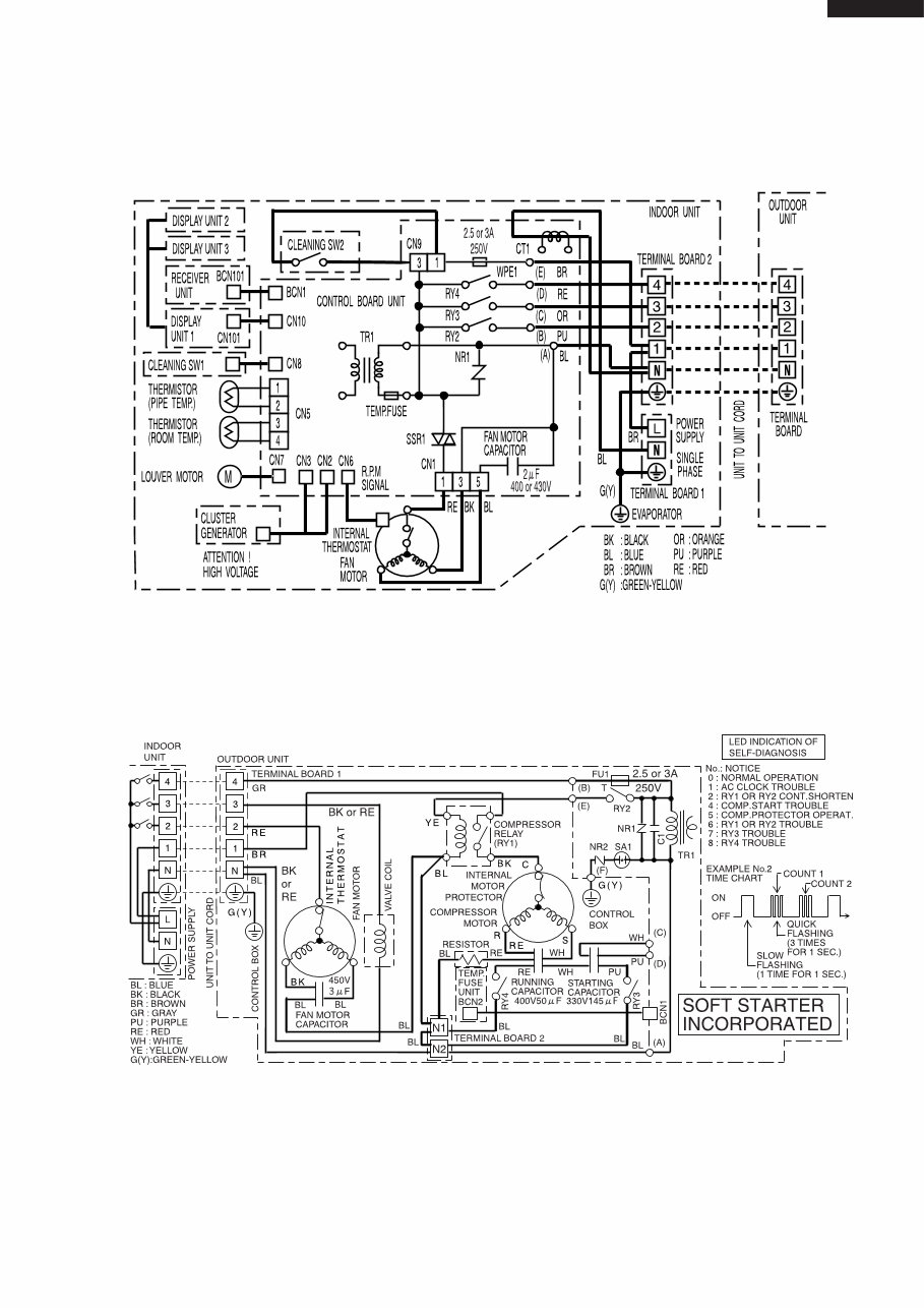
5
AY-AP18CJ
AY-AP24CJ
AE-A18CJ
AE-A24CJ
Figure W-3. Wiring Diagram for AY-AP24CJ
Figure W-4. Wiring Diagram for AE-A24CJ
AY-AP18CJ
AY-AP24CJ
AE-A18CJ
AE-A24CJ
6
ELECTRICAL PARTS
Part Part Name Items Specifications
No. AY-AP18CJ AY-AP24CJ
1 Terminal Board Rating 300V 25A
2 Fan motor Rating 400V 2μF
Capacitor
3 Relay-1 Rating AC250V 20A –
(RY1) Coil Volt.; 12V
4 Relay-2 Rating AC250V 3A
(RY2, RY3, RY4) Coil Volt.; 12V
5 Printed Wiring Material Paper Base Phenolic Resin (UL 94V-0)
Board
6 Transformer Rating Pri 220 - 240VAC Sec. 19.0VDC
7 Fan motor Rating 220 - 240VAC 50Hz 41W 4-Pole
Type MLA999
Thermal Protector Cut off 135±10˚C
(Internal)
8 Power Supply Rating 3G 2.5mm
2
–
Cord H05VV-F –
9 Louver Motor Rating DC12V
Type MP24GA
Part Part Name Items Specifications
No. AE-A18CJ AE-A24CJ
1 Terminal Board Rating 300V 25A
2 Fan motor Rating 450V 3μF 450V 3μF
Capacitor
3 Running Rating 400V 50μF 400V 50μF
Capacitor
4 Compessor Rating AC220 - 240V 50Hz 1500W AC220 - 240V 50Hz 2200W
Type PH33VPET 2JS464D3AA02
5 Protector Manufacturer Ubukata Industries Co., Ltd. TEXAS INSTRUMENTS
Type UP3QF0302-T09 (INTERNAL) 3HM529-36V (INTERNAL)
Cutt off 130˚C 120˚C
6 Fan motor Rating 220 - 240VAC 50Hz 71W 6-Pole 220 - 240VAC 50Hz 75W 6-Pole
Type MLB002 MLB015
Thermal protector Cut off 135˚C±5˚C
(Internal)
7 Compressor Rating – AC250V 30A
Relay (RY1) Coil volt: 200 -240VAC
8 Starting Rating – 330V 145μF
Capacitor
7
AY-AP18CJ
AY-AP24CJ
AE-A18CJ
AE-A24CJ
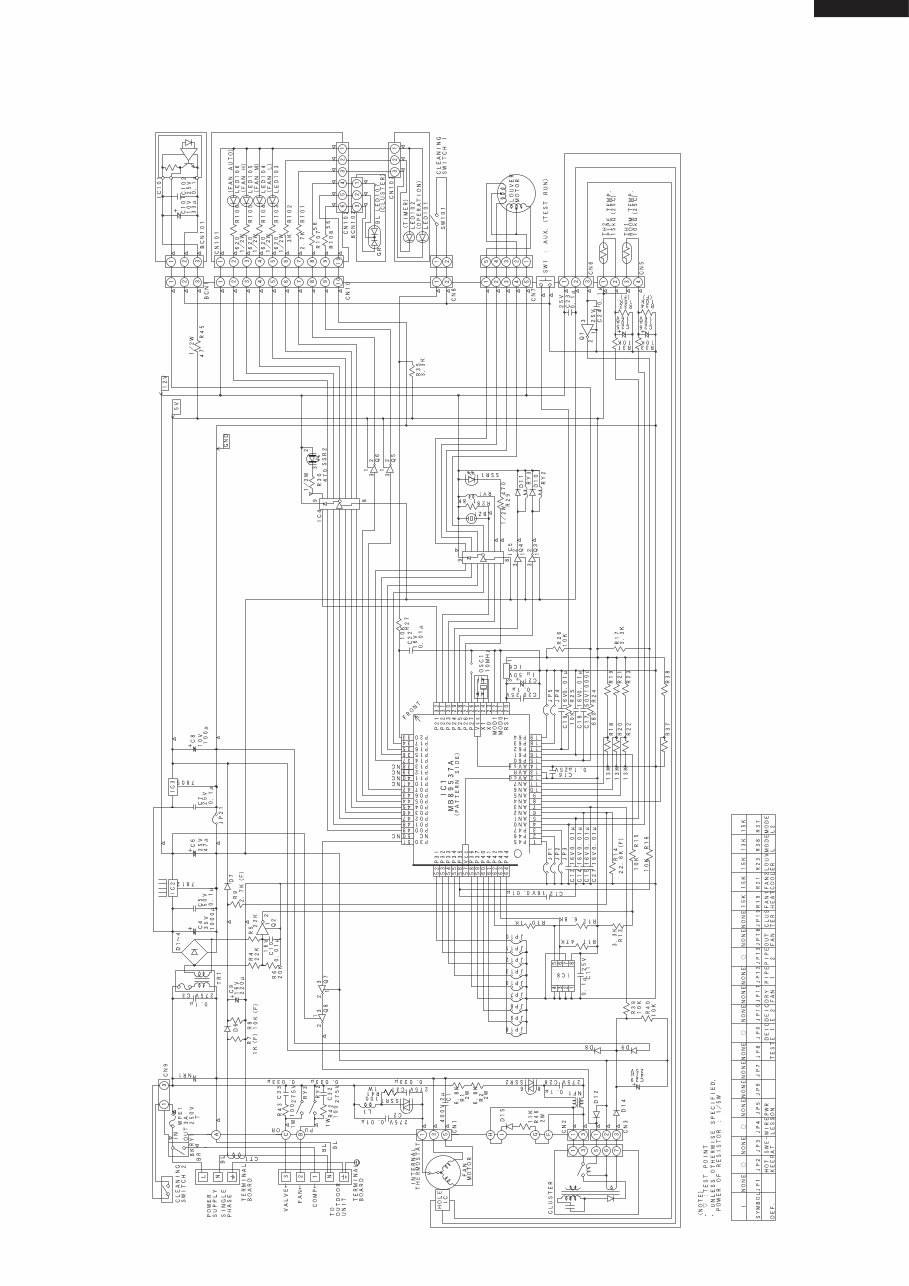
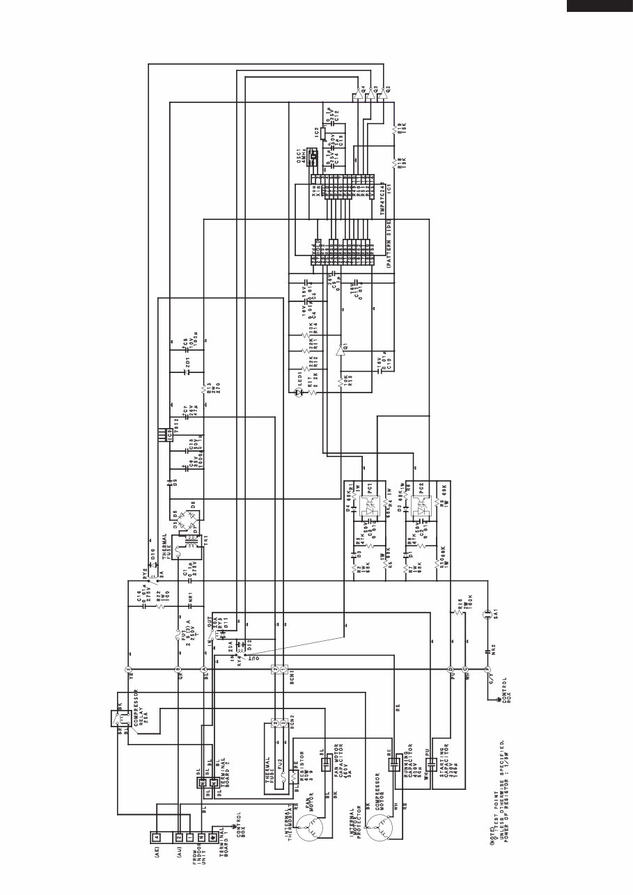
MICROCOMPUTER CONTROL SYSTEM
Figure L-1. Electronic Control Circuit Diagram for AY-AP18CJ
AY-AP18CJ
AY-AP24CJ
AE-A18CJ
AE-A24CJ
8
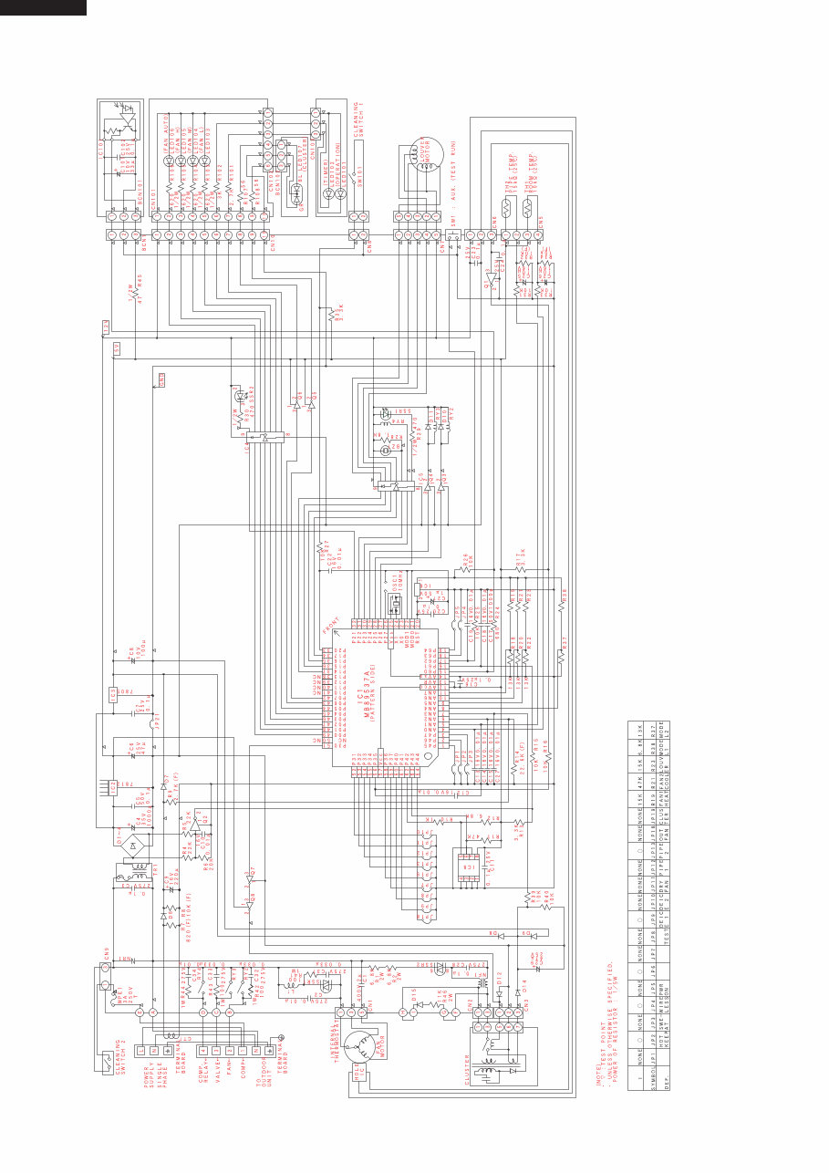
Figure L-2. Electronic Control Circuit Diagram for AY-AP24CJ
9
AY-AP18CJ
AY-AP24CJ
AE-A18CJ
AE-A24CJ
Figure L-3. Electronic Control Circuit Diagram for AE-A24CJ
AY-AP18CJ
AY-AP24CJ
AE-A18CJ
AE-A24CJ
10
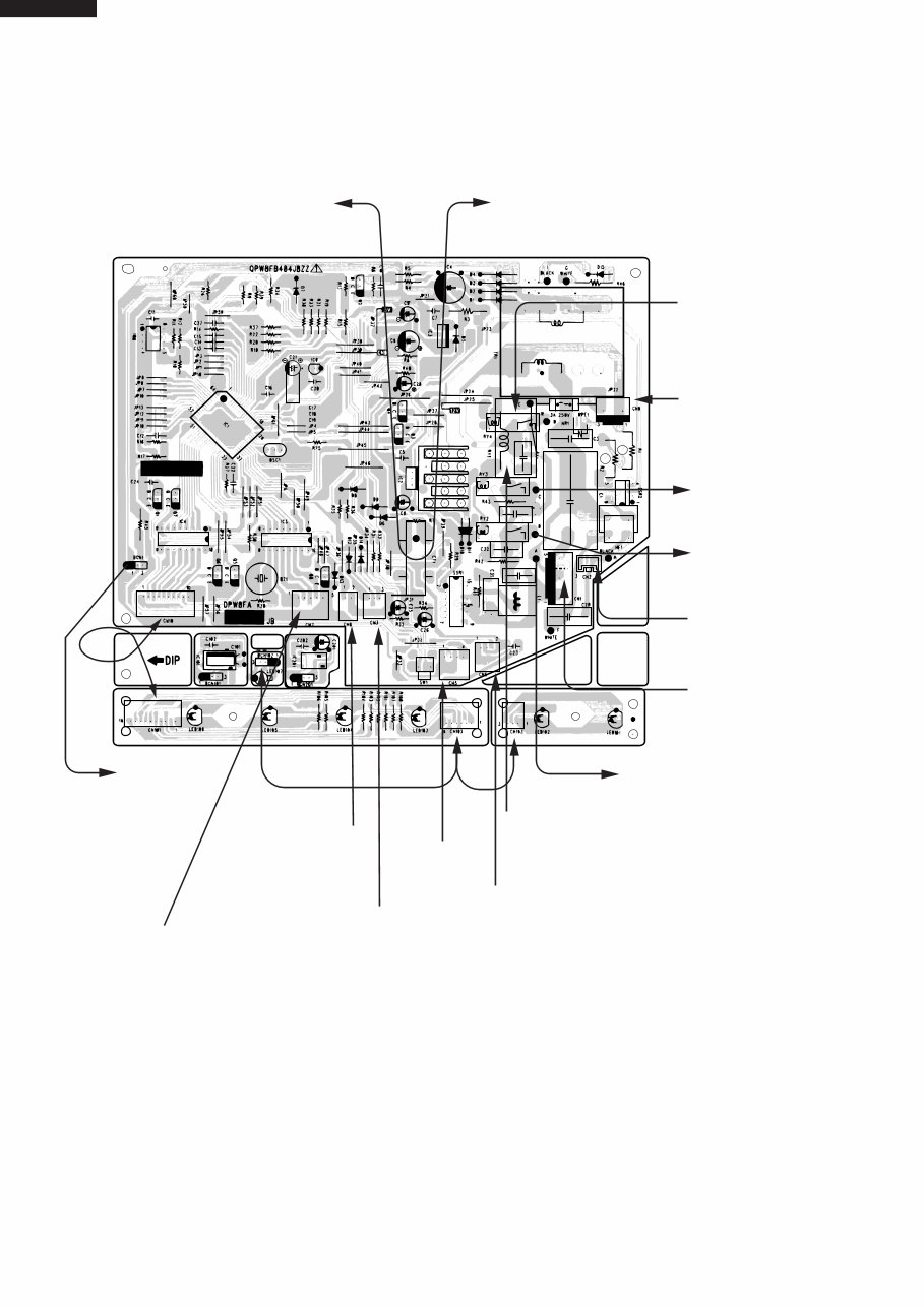
Figure L-4. Printed Wiring Diagram for AY-AP18CJ
C2
R44
OUT
C34
C33
TO
TERMINALBOARD
BOTTOM " N "
TO
TERMINALBOARD
TOP " N "
FROM
TERMINALBOARD
BOTTOM
" L " , " BROWN "
FROM
CLEANING
SWITCH 2
TO
TERMINALBOARD
TOP " 3 "
TO
TERMINALBOARD
TOP " 2 "
FROM
CLUSTER
GENERATOR
FROM
FAN MOTOR
TO
TERMINALBOARD
TOP " N "
FROM
TERMINALBOARD
TOP " 1 ", " BLACK "
FROM
FAN MOTOR
FROM
THERMISTOR
FROM
CLUSTER
GENERATOR
FROM
CLEANING
SWITCH 1
FROM
LOUVER MOTOR
BCN101
(BCN201)
You're Reading a Preview
What's Included?
Fast Download Speeds
Online & Offline Access
Access PDF Contents & Bookmarks
Full Search Facility
Print one or all pages of your manual
$27.99
Viewed 41 Times Today


Secure transaction
What's Included?
Fast Download Speeds
Online & Offline Access
Access PDF Contents & Bookmarks
Full Search Facility
Print one or all pages of your manual
$27.99
This service repair manual in PDF format contains comprehensive information for repairing, servicing, rebuilding, or maintaining your Split System Room Air Conditioners. It covers every part and includes all the information found in costly CD-ROM manuals.
- Service Manual Covers:
- Specifications
- External Dimensions
- Wiring Diagrams
- Electrical Parts
- Microcomputer Control System
- Functions
- Troubleshooting Guide of Control Circuit
- Refrigeration Cycle
- Performance Curves
- Refrigerant Pipe Installation Works
- Disassembling Procedure
- Replacement Parts List
- Plus more...
Features:
- Format: PDF
- Easy to read and understand
- Plenty of Pictures / Diagrams
- High-Quality Printable Manual
Instant Access:
After your payment, you will have instant access to your manual. No shipping fee, no waiting on postal delivery, you can start doing your repairs today!


