Wisconsin Tra-10d Tr-10d Owners & Parts List Manual access
What's Included?
Lifetime Access
Fast Download Speeds
Online & Offline Access
Access PDF Contents & Bookmarks
Full Search Facility
Print one or all pages of your manual
WISCONSIN HEAVY DUTY ENGINES INSTRUCTION BOOK AND PARTS LIST MODELS TRA-10D, TR-10D ISSUE MM-320-C WORLD’S LARGEST BUILDERS OF HEAVY DUTY AIR COOLED ENGINES
I M P O R T A N T STARTING AND OPERATING OF NEW ENGINES Careful breaking in of a new engine will greatly increase its life and result in trouble-free operation. A factory test is not sufficient to establish the polished bearing surfaces, which are so necessary to the proper perform- ance and long life of an engine. Neither is there a quick way to force the establishment of good bearing surfaces. These can only be obtained by running a new engine carefully and under reduced speeds and loads for a short time, as follows: First, be sure the engine is filled to the proper level with a good quality of engine oil , see “Grade of Oil” chart. Before a new engine is put to its regular work, the engine should be oper- ated at low idle speed (1000 to 1200 R.P.M.) for one half hour, without load. The R.P.M. should then be increased to engine operating speed, still without load, for an additional two hours. If at all possible, operate the engine at light loads for a period totaling about eight hours, before maximum load is applied. This will greatly in- crease engine life. The various bearing surfaces in a new engine have not been glazed, as they will be with continued operation, and it is in this period of “running in,” that special care must be exercised, otherwise the highly desired glaze will never be obtained. A new bearing surface that has once been damaged by carelessness will be ruined forever. THEREFORE READ INSTRUCTIONS CAREFULLY A copy of this manual is sent out with each engine. All points of opera- tion and maintenance have been covered as carefully as possible but if further information is required, inquiries sent to the factory will receive prompt attention. When writing the factory ALWAYS GIVE THE MODEL AND SERIAL NUMBER of engine referred to. Extra copies of this manual are $1.00 each. WISCONSIN MOTOR CORPORATION MILWAUKEE, WISCONSIN 532466
1 MI-935-2 BOOK OF INSTRUCTIONS WISCONSIN SINGLE CYLNDER ENGINES MODEL TRA-10D 3-1/8” Bore – 2-7/8” Stroke 22.05 cu. In. Displacement MODEL TR-10D 3-1/8” Bore – 2-5/8” Stroke 20.2 cu. In. Displacement WISCONSIN MOTOR CORPORATION Milwaukee, Wisconsin 53246, U. S. A.
MI-476 2 INTRODUCTION This manual has been compiled to suit the service requirements of the basic engines and accessories most commonly supplied with engines. Wisconsin Motor Corporation adapts its engines to suit individual customer re- quirements whenever practical. However, it would become too involved to include all variations in one manual; therefore, should any problems arise concerning engine servicing, we advise that a Wisconsin distributor or authorized service station be contacted, as they are capable of identifying all parts by the specifi- cation numbers stamped on the name plate of engine. A listing of approved Wisconsin service stations appears in the back of this manual. WISCONSIN heavy duty air cooled engines are of the most advanced design and are built in a modern factory, equipped with the latest machinery available. Only the best materials, most suitable for the particular part, are used. During produc- tion, every part is subjected to the most rigid inspection, as are also the com- pletely assembled engines. After assembly, every engine is operated on its own power for several hours. All adjustments are carefully made so that each engine will be in perfect operating condition when it leaves the factory. Back of the Wisconsin Motor Corporation are more than fifty years of engineering experience in the design of gasoline engines for every conceivable type of ser- vice. The performance of these engines is proof of the long satisfactory service you too can expect from your engine. Like all fine machinery, the engine must be given regular care and be operated in accordance with the instructions. SAFETY PRECAUTIONS Precaution is the best insurance against an accident. Never fill fuel tank while engine is in operation or hot, to avoid the possibility of spilled fuel causing a fire. Never operate engine in a closed building unless the exhaust is piped outside. This exhaust contains carbon monoxide, a poisonous, odourless and invisible gas, which if breathed causes serious illness and possible death. Never make adjustments on machinery while it is connected to the engine, with- out first removing the ignition cable from the spark plug. Turning over the ma- chinery by hand during adjusting or cleaning might start the engine and machin- ery with it, causing serious injury to the operator. Keep this book handy at all times, familiarize yourself with the operating instructions.
INDEX 3 MI-936-2 PAGE Air Cleaner ..................................................... 10 Battery Ignition .............................................. 11 Breaker Point Adjustment .............................. 11 Breather – Crankcase ..................................... 10 Carburetor – Adjustment ............................... 9 Carburetor Repair – See Manufacturer’s Bulletin in Back of Manual. Compression ........................................................ 15 Compression Release ........................................... 7 – 22 Compression – Restoring ..................................... 14 Cooling ................................................................. 7 Cross Section of Engine ........................................ 6 Disassembly and Reassembly ............................... 16 Breaker Push pin and Bushing ........................... 22 Camshaft and Valve Tappets ............................. 22 Carburetor and Air Cleaner ............................... 17 Connecting Rod and Piston ............................... 20 Crankshaft ......................................................... 23 Cylinder .............................................................. 23 Cylinder Head and Spark Plug ............................ 17 Flywheel ............................................................ 19 Flywheel Shroud ................................................ 17 Fuel Tank ........................................................... 17 Gear Cover ......................................................... 20 Piston, Ring and Rod Clearance Chart ............... 21 Piston Rings ....................................................... 21 Starter Sheave ................................................... 17 Stator Plate ........................................................ 23 Valves and Seat Insert ....................................... 18 Valve Guides ...................................................... 18 End Play ................................................................ 23 Engine Illustration ................................................ 4 – 5 Engine Speed ........................................................ 24 Electrical Equipment Wiring Circuits and Motor-Generator ............................................... 13 Fuel ....................................................................... 8 Fuel Pump ............................................................ 8 General Design ..................................................... 7 Governor Adjustment .......................................... 24 PAGE Governor - Description ......................................... 7 Governor - Operation .......................................... 23 Horsepower .......................................................... 7 Ignition (Description) ........................................... 7 Ignition Spark ....................................................... 10 Lubrication ........................................................... 7 Lubrication System ............................................... 7 Magneto Ignition .................................................. 11 Magneto Service Instructions .............................. 12 Oil – Grade of and Classification .......................... 8 Parts List Section .................................................. 25 Rotation ................................................................ 7 Safety Precautions ................................................ 2 Service Station Directory – See Back Of Manual. Spark Plug ............................................................ 14 Starting and Operating Instructions .................... 7 Starting – Procedure ............................................ 8 Starting and Operation of New Engine (See Inside of Front Cover ). Stopping Engine ................................................... 9 Storage of Engine For Winter ............................... 14 Testing Rebuilt Engine .......................................... 16 Timing ................................................................... 11 Timing Marks ....................................................... 22 Troubles - Causes and Remedies .......................... 15 Backfires Through Carburetor ........................... 16 Ignition ............................................................... 15 Knocks ................................................................ 16 Misses ................................................................ 16 Overheats .......................................................... 16 Starting Difficulties ........................................... 15 Stops .................................................................. 16 Surges or Gallops ............................................... 16 Valves – Grinding and Tolerance Chart ................ 18 Tappet Adjustment .............................................. 19 Warm-Up Period – Overspeeding ........................ 9
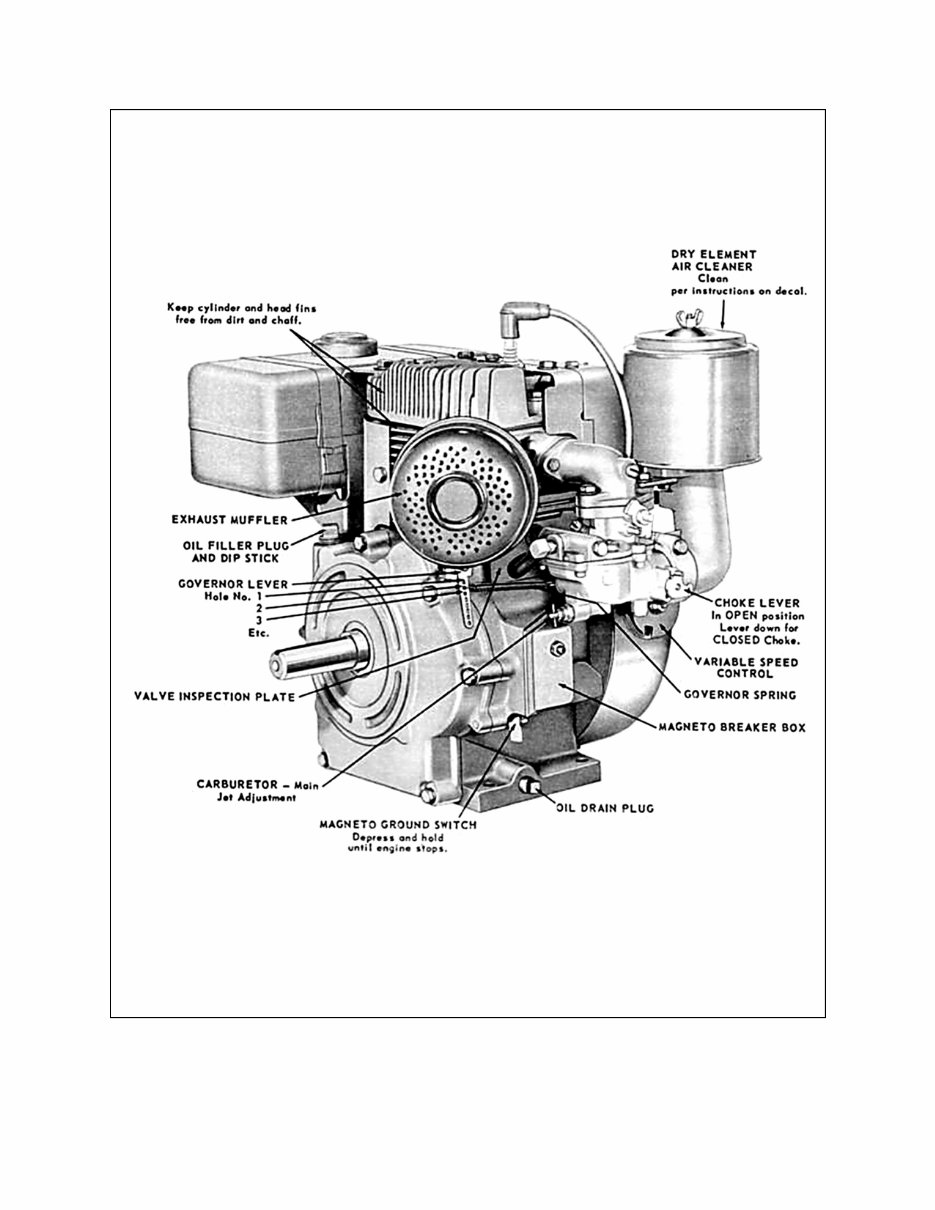
MI-937-2 4 Fig. 1 289860C TAKE-OFF (rear) and LEFT HAND SIDE VIEW of ENGINE
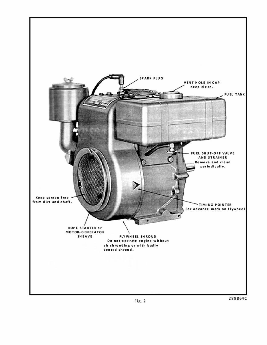
5 MI-938-2 FAN END (front) and RIGHT HAND SIDE VIEW of ENGINE
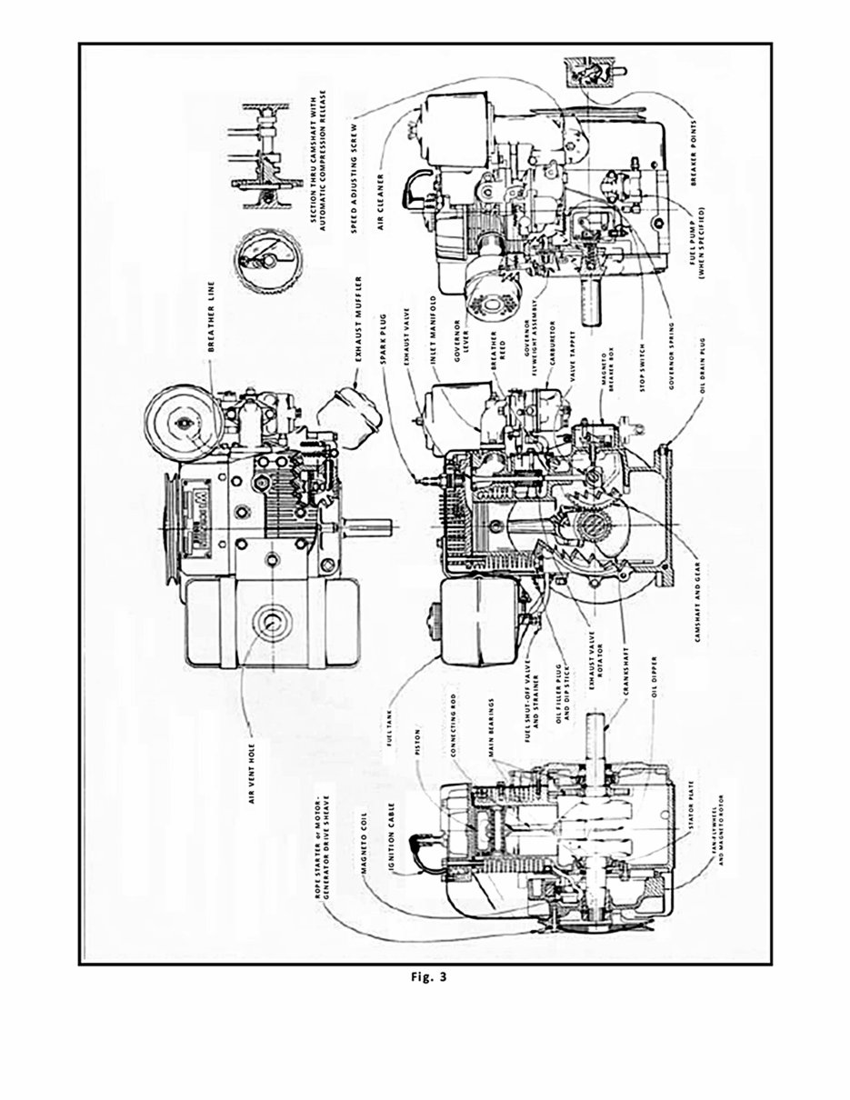
MI-939-2 6 SECTIONAL VIEWS OF ENGINE
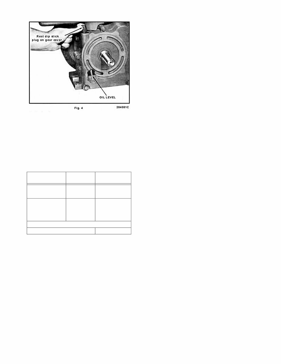
7 MI-1058 GENERAL DESIGN Wisconsin engines are of the four cycle type, in which each of the four operations of suction, compression, expansion and exhaust constitutes a complete stroke. This gives one power stroke for each two revolutions of the crankshaft. COMPRESSION RELEASE A component part of the camshaft that operates auto- matically and trouble free. Permits fast and effortless starting with no dangerous “kick back”. COOLING Cooling is accomplished from a flow of air circulated over the cylinder and head of the engine, by a combi- nation fan-flywheel encased in a sheet metal shroud. The air is divided and directed by ducts and baffle plates to insure uniform cooling of all parts. Never operate an engine with any part of the shrouding removed, because this will retard the air cooling. Keep the cylinder and head fins free from dirt and chaff. Improper circulation of cooling air will cause engine to overheat. CARBURETOR The proper combustible mixture of gasoline and air is furnished by a balanced carburetor, giving correct fuel to air ratios for all speeds and loads. IGNITION The spark for ignition of the fuel mixture is furnish- ed by a high tension flywheel magneto. A stator plate functions as an engine bearing plate as well as a sup- port for the coil and core. The permanent magnet is an integral part of the flywheel, and a breaker box on the side of the crankcase contains the points, condenser and stop switch. A push pin, actuated by the engine camshaft, operates the breaker arm at half engine speed. Battery ignition (12 volt) can be furnished in place of magneto, when specified. An ignition coil and breaker assembly are the means of inducing high voltage to the spark plug. Battery is not furnished by Wisconsin Motor Corporation. LUBRICATION SYSTEM An oil dipper on the connecting rod provides for a splash type lubrication system. The action of the dip- per striking the oil in the crankcase provides ample lub- rication for all internal parts of the engine. GOVERNOR A governor of the centrifugal flyball type controls the engine speed by varying the throttle opening to suit the load imposed upon the engine. Manually operated variable speed controls are available for practically all applications. ROTATION The rotation of the crankshaft is clockwise when viewing the flywheel or starting end of the engine. This gives counter-clockwise rotation at the power take-off end of the crankshaft. Horsepower given in the accompanying chart is for an atmospheric temperature of 60° Fahrenheit at sea level and at a Barometric pressure of 29.92 inches of mercury. HORSEPOWER For each inch lower the Barometric pressure drops, there will be a loss in horsepower of 3½%. For each 10° temperature rise there will be a reduce- tion in horsepower of 1%. For each 1000 ft. altitude above sea level there will be a reduction in horsepower of 3½%. The friction in new engines cannot be reduced to the ultimate minimum during the regular block test, but engines are guaranteed to develop at least 85 per cent of maximum power when shipped from the fac- tory. The power will increase as friction is reduced during the first few days of operation. The engine will develop at least 95% of maximum horsepower when friction is reduced to a minimum. INSTRUCTIONS FOR STARTING AND OPERATING LUBRICATION Before starting a new engine, fill crankcase base with the correct grade of engine oil, as specified in “grade of oil chart”. Fill thru the dipstick plug opening illus- trated in Fig. 4, with 1 quart of oil. For run-in of new engines, use same oil as recom- mended in Grade Of Oil Chart. The oil level mark is indicated by a groove on the dip stick as shown in Fig 4. Check oil level by resting the bottom of plug at the top of oil filler opening on gear cover. (Do not thread in place to check level). Too much emphasis cannot be given to the matter of oil selection. High grade oil of the body suited to the requirements of your engine is the most important sin- gle item in the economical operation of the unit, yet R.P.M MODEL TRA-10D 2000 5.4 2200 6.1 2400 6.8 2600 7.6 2800 8.3 3000 8.8 3200 9.4 3400 9.8 3600 10.1
MI-1059 8 SEASON OR TEMPERATURE GRADE OF OIL EXAMPLE Spring, Summer Or Autumn +120°F to +40°F SAE 30 Mobiloil A Winter +40°F to +15°F +15°F to 0°F Below Zero SAE 20-20W SAE 10-10W SAE 5W – 20W Mobiloil Arctic Mobiloil 10W Mobiloil 5W-20W Use oils classified as Service MS Crankcase Capacity 1 Quart it is the cheapest item of operating cost. Select your oil solely on quality and suitability – never on price – for no one thing is so sure to bring about unsatifac- tory performance and unnecessary expense as incor- rect lubrication. High-grade, highly refined oils corresponding in body to the S.A.E. (Society of Automotive Engineers) Viscosity Numbers listed in the following chart will prove economical and assure long engine life. GRADE OF OIL Important: S.A.E. Viscosity Numbers classify oils in terms of body only, without consideration of quality or character; therefore we list certain grades of Mobil oil as typical examples of lubricants possessing the qualities we believe desirable in oils for Wisconsin engines. We plainly state that these grades of Mobil- oils are listed because of their recognized quality and world-wide distribution. There are other high quality oils on the market that are equally satisfac- tory for Wisconsin engines. Follow summer recommendations in winter if engine is housed in warm building. Check oil level every 8 hours. Change oil every 50 hours of operation. To drain oil, remove drain plug illustrated in Fig. 1. Oil should be drained while engine is hot, as it will then flow more freely. SERVICE CLASSIFICATION OF OIL In addition to the S.A.E. Viscosity grades, oils are also classified according to the severity of engine ser- vice. Use oil classified as Service MS. This type of oil is for engines performing under unfavourable or severe operating conditions such as: high speeds, constant starting and stopping, operating in extreme high or low temperatures and excessive idling. FUEL The fuel tank should be filled with a good quality gasoline free from dirt and water. The capacity of the tank is one gallon. Some of the poorer grades of gaso- line contain gum which will deposit on valve stems, piston rings, and in the various small passages of the carburetor, causing trouble in operating, and in fact might prevent the engine from operating at all. Use only reputable, well known brands of gas- oline of the REGULAR GRADE. The gasoline should have an octane rating of at least 90. Fuel with a low octane rating will cause detona- tion, and if operation is continued under this condi- tion, severe damage will result to the engine. The cylinder and piston will be scored, head gasket blown out, bearings will be damaged, etc. Be sure that air vent in fuel tank cap is not plugged with dirt, as this would prevent fuel from flowing to the carburetor. FUEL PUMP An engine equipped with fuel pump; when starting for the first time, or when engine has been out of opera- tion for a while, should be primed to prevent hard starting. Disconnect ignition wire at the spark plug to prevent engine from accidentally starting. Then, turn the engine over about 6 or 7 times, by means of the rope starter sheave, to actuate the fuel pump and thus fill the carburetor bowl with gasoline. Be sure and connect ignition wire after priming has been ac- complished. Fuel pump is an optional accessory. Due to special machining of crankcase, fuel pump can be furnished only upon request when engine is ordered. Instruc- tions for fuel pump maintenance and repair are located in the back of this manual. STARTING STARTING PROCEDURE (Fig. 5 and Fig. 6) 1. Check crankcase oil level and gasoline supply. Open fuel shut-off valve. 2. The main jet adjustment on the carburetor is made when engine is tested at the factory. Refer to ‘Carburetor – Adjustment’ for further information. 3. Disengage clutch if furnished. 4. Set throttle about 1/2 open if variable speed gov- enor control is furnished. With a fixed speed gov- ernor, spring will hold throttle open for starting.
This is the official Operators / Owners manual for the Wisconsin Tra-10d Tr-10d. Please note that this is not a physical manual but a digital file that will be sent to your email. You can access the manual within minutes of your purchase and it is compatible with all versions of Windows & Mac, smart phones, iPads, flash drives, hard drives, etc. The manual is printable and available in English language.
An owner's manual, also known as an instruction manual, contains safety instructions, assembly, installation, setup, normal usage, programming, maintenance, troubleshooting instructions, service locations, regulatory code compliance information, product technical specifications, and warranty information. It also includes an exploded view of the manual.
Our informative Official Illustrated Parts Lists manuals contain all the information you need for repairs, parts lookup, or routine maintenance. It covers general information, safety, basic operation, exploded views, images, routine maintenance, and more. You can print off the page that contains the part you need and take it to your local dealer or search the internet to purchase the required part.
We provide various repair service manuals, workshop manuals, repair manuals, owners operators manuals, and illustrated parts manuals for UTVs, tractors, weapons, laptops, notebooks, motorcycles, ATVs, quads, snowmobiles, Seadoo, equipment, small engines, inboards, outboards, and more. All manuals are in an electronic format and will be sent to your email.
Recently Viewed
5,521,897Happy Clients
2,594,462eManuals
1,120,453Trusted Sellers
15Years in Business
Price:
Actual Price:
Wisconsin Tra-10d Tr-10d Owners & Parts List Manual access