

VW Volkswagen 1.9 TDI Industrial engine workshop service manual - NOW
What's Included?
Fast Download Speeds
Online & Offline Access
Access PDF Contents & Bookmarks
Full Search Facility
Print one or all pages of your manual
1,9 ltr-TDI-Industrial Engine
Technical Status: 4/1999

2
• Combustion process . . . . . . . . . . . . . . . .3
• Injectors . . . . . . . . . . . . . . . . . . . . . . . . .4
• Needle Lift Sender . . . . . . . . . . . . . . . . .5
• Air-mass Flow Meter . . . . . . . . . . . . . . .6
• Modulating piston movement sender . .7
• Installation position . . . . . . . . . . . . . . . .8
• System overview . . . . . . . . . . . . . . . . .10
• Fuel regulation . . . . . . . . . . . . . . . . . . .12
• Injection commencement control . . . . .17
• Exhaust gas recirculation . . . . . . . . . . .22
• Charge pressure control . . . . . . . . . . .24
• Glow plug system . . . . . . . . . . . . . . . .26
• Emission characteristics . . . . . . . . . . . .27
• Internal functions in the control unit . .29
• Self-diagnosis . . . . . . . . . . . . . . . . . . .30
• Performance diagram . . . . . . . . . . . . .31
• Specifications . . . . . . . . . . . . . . . . . . . .32
Detailed instructions regarding testing, adjustment and repair can be found in
the Workshop Manual "Volkswagen Industrial Engine".
Contents
3
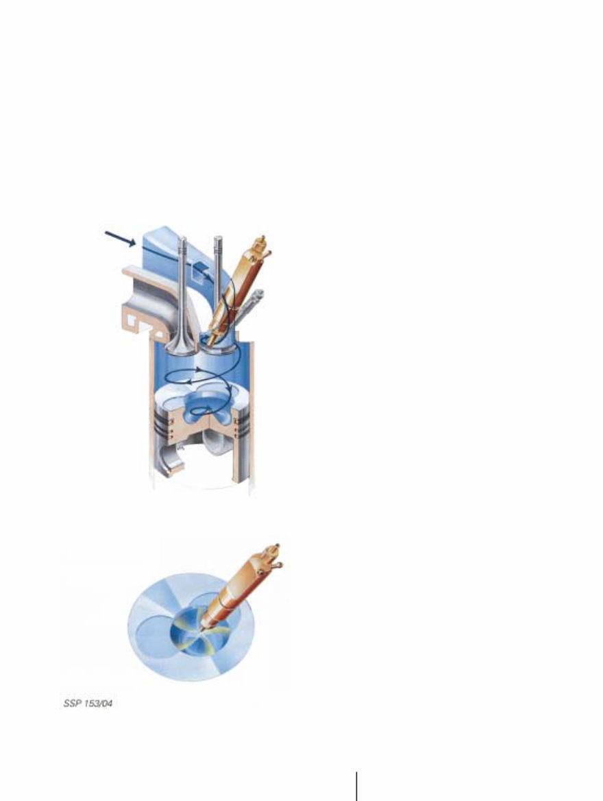
In the direct injection engine, diesel fuel is injected directly into the main combustion
chamber. This results in more efficient combustion and lower consumption.
The intake port, pistons and injectors have been designed specifically to optimise
the combustion process with respect to noise emission and running characteristics.
Inlet swirl port
The intake port is shaped in such a way that it
induces a swirling movement of the intake air
and, as a result, produces greater turbulence
in the combustion chamber and piston recess.
Piston recess
The shape of the piston recess has been opti-
mised specially for this engine.
5-hole injector
The fuel is injected into the piston recess in
two stages and is ignited by the hot air.
The two-stage injection process avoids a sharp
pressure rise.
Combustion process
4
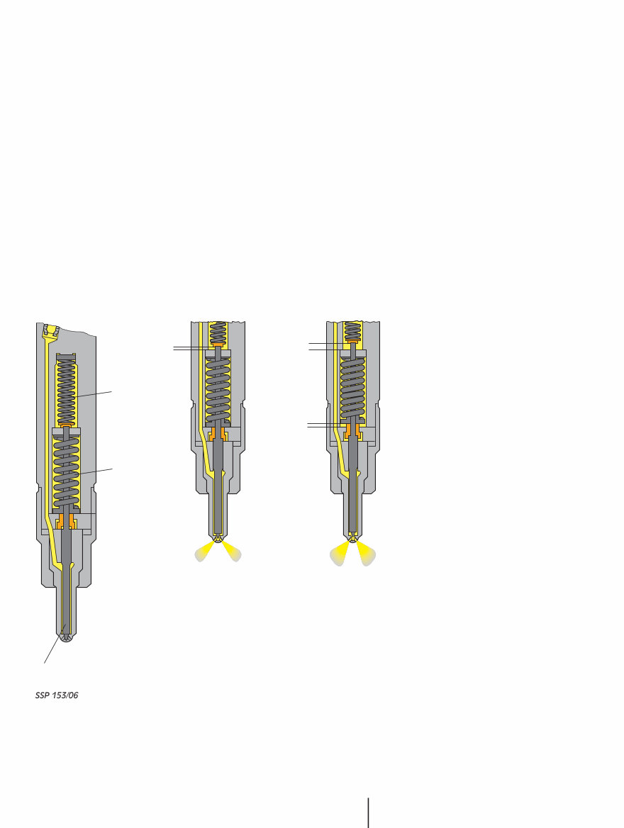
Two-spring injector holder
To minimise the combustion noise level in the diesel engine and keep mechanical
load low, it is necessary for the pressure to rise gently in the combustion chamber.
In the case of chamber-type diesel engines, this gentle rise in pressure is achieved,
first, by injecting fuel into the pre-chamber or the swirl chamber and, secondly, by
using pintle-type injectors. Also, the fuel should be injected gradually, not all at once.
A two-spring injector holder has been developed for the 1.9-ltr. direct injection
engine. This injector holder, a key factor contributing to the engine’s "soft" combus-
tion characteristic, allows fuel to be injected in two stages.
The injector is designed as a five-hole nozzle.
Function
Two springs with different
thicknesses are integrated
in the injector holder.
The springs have been
adapted in such a way
that the injector needle is
only lifted against the
force of the first spring
when injection starts.
A small quantity of fuel is
pre-injected through the
small gap which appears
at low pressure.
This pre-injection cycle produces a gentle rise in the combustion pressure
and creates the conditions for igniting the main fuel quantity.
As the injection pump delivers more fuel than can actually flow through
the small gap, the pressure in the injector rises. The force of the second
spring is overcome, and the injector needle is lifted further. The main
injection cycle now follows at a higher injection pressure.
Injector needle
Injector needle
Spring 1
Stroke 2
Stroke 1
Stroke 1+2
Spring 2
5
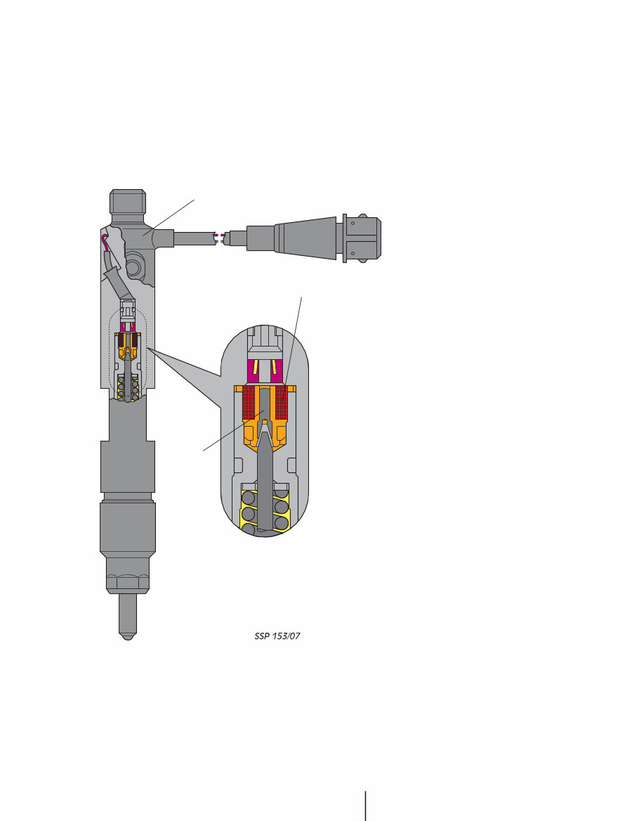
The injector of the 3rd cylinder is equipped with a needle lift sender (G80) for regis-
tering the point of commencement of injection.
The sender signals the actual opening time of the injector to the control unit. This
signal provides the control unit with feedback on whether the point of commence-
ment of fuel injection conforms to the map.
Function
Needle lift sender G80 is a
solenoid and is supplied with a
constant current by the control
unit. This produces a magnetic
field.
A pressure pin inside the sole-
noid forms an extension to the
end of the injector needle. The
movement of the injector nee-
dle alters the magnetic field
and causes distortion of the
DC voltage applied to the sole-
noid.
The control unit calculates the
actual point of commencement
of fuel injection from the time
difference between the needle
lift pulse and the TDC signal
supplied by the engine speed
sender. At the same time, the
system compares the actual
point of commencement of
injection with the setpoint
stored in the control unit and
corrects any deviations from
the setpoint.
Substitute function
If the needle lift sender fails, an emergency running program is started. In this pro-
gram, the commencement of fuel injection is controlled according to fixed setpoints
as defined in a map. The injection quantity reduced in addition.
Needle Lift Sender
Solenoid
Pressure pin
Injector holder
6
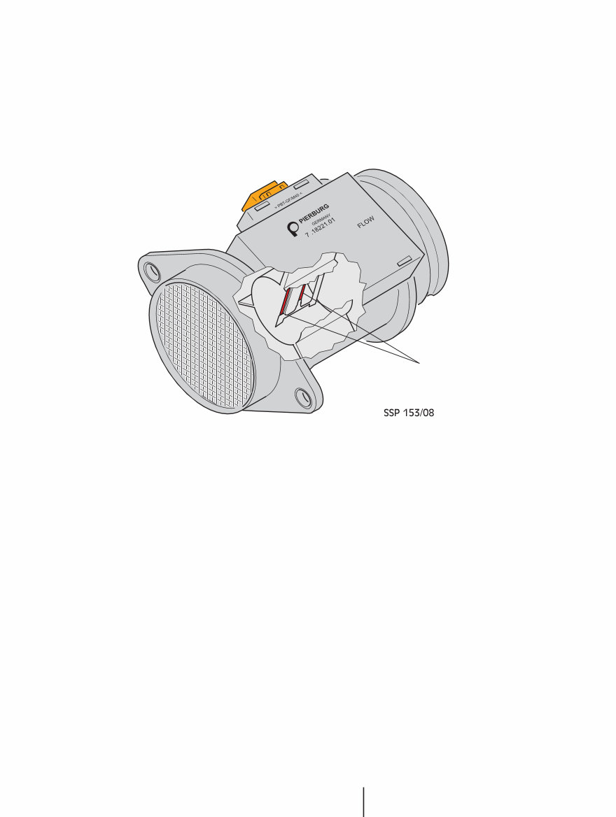
The task of the air-mass flow meter is to measure the fresh air mass supplied to the
engine.
This fresh air mass is used to calculate the exhaust gas recirculation rate and the
permissible injection quantity.
Air-mass flow meter
Air-mass flow meter
Function
A heated surface, the hot film, is regulated to a constant temperature.
The intake air cools the hot film as it flows past.
The current serves as a measure of the intake air mass necessary to keep the tem-
perature of the hot film constant.
Substitute function
If the air-mass flow meter fails, the control unit defaults a fixed air mass value.
This fixed value is calculated such that a reduction in engine performance can only
occur in the part-throttle range.
Advantages of hot-film air mass metering
Air-mass data can be acquired without additional air pressure and temperature
sensors
Reduced flow resistance compared to sensor flap air-flow metering
It is no longer necessary to burn off the hot wire as in the hot wire air-mass flow
meter.
Hot film
7
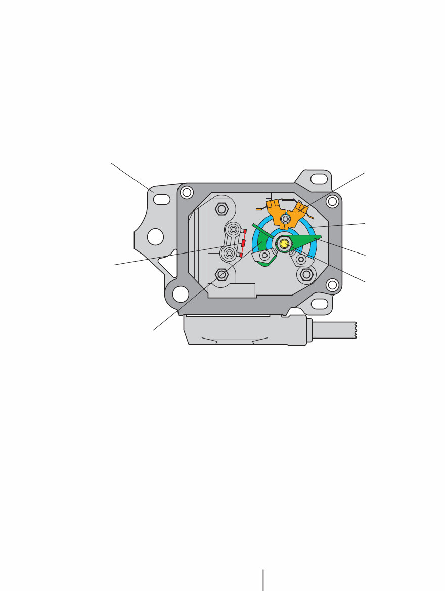
Modulating piston movement sender G149 supplies the control unit with information
on the momentary position of the quantity adjuster in the injection pump.
The injected fuel quantity is calculated from this information.
Sender G149 is a non-contact sensor for measuring the angle of rotation.
It is attached to the eccentric shaft of the quantity adjuster.
Function
An alternating magnetic field is produced in a specially shaped iron core by AC volt-
age. A metal ring attached to the eccentric shaft moves along the iron core and influ-
ences this magnetic field. The change in the magnetic field is evaluated electronical-
ly in the control unit and indicates the position of the quantity adjuster.
Substitute function
If the control unit does not receive a signal from the sender for modulating piston
movement, the engine is turned off for safety reasons.
The new non-contact sender offers the following advantages:
High wear resistance
High interference immunity
Low susceptibility to temperature fluctuation
Modulating Piston Movement Sender
Iron core
Distributor injection pump
Fuel temperature
sensor G81
Stationary metal ring
Eccentric shaft
Movable metal ring
Coil with AC voltage
SSP 153/09
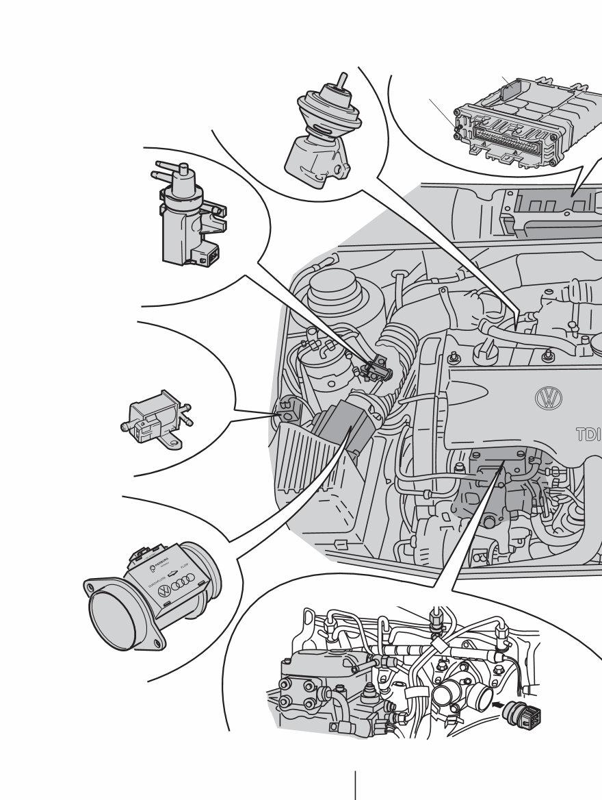
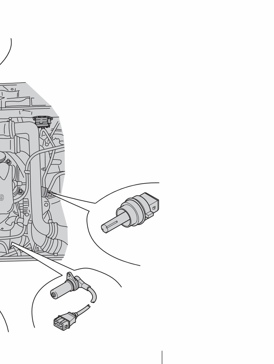
8
Exhaust gas recirculation
valve N18
Air-mass flow meter G70
Injector with
needle lift sender G80
Distributor injection pump
Coolant temperature sender G6
E
Intake manifold pressure sender
Solenoid valve for charge
pressure control N75
EGR valve
Hose connection
Air-mass flow meter
9
Engine speed sender G28
Intake manifold temperature
sensor G72
ontrol unit J248
To optimise engine performance with respect to torque delivery, consumption and
emission in every operating situation, the EDC control unit refers to 25 maps and
characteristic curves.
Sensors supply the control unit with information regarding the vehicle’s momentary
operating state.
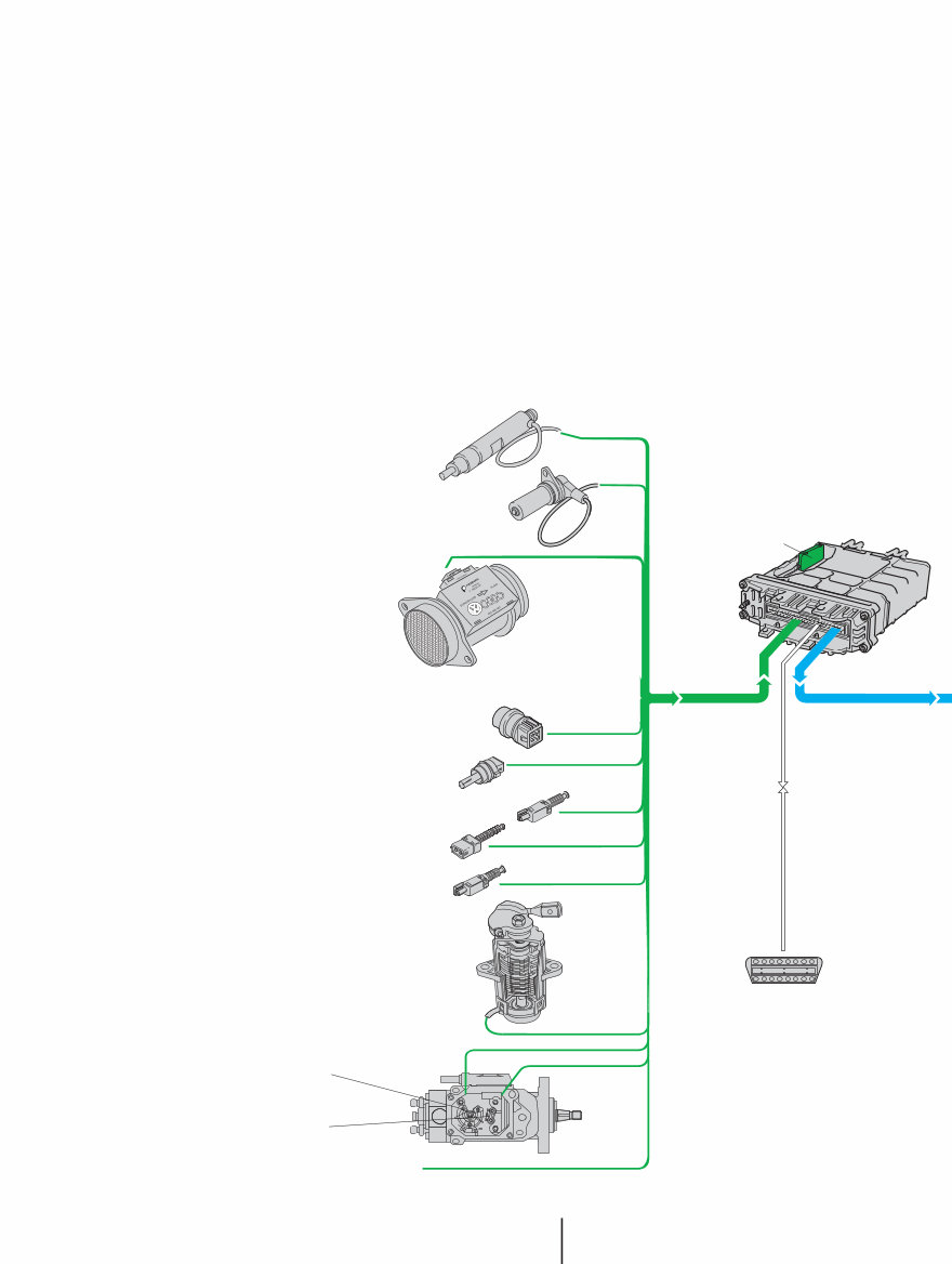
10
System overview
Needle lift sender G80
Engine speed sender G28
Air-mass flow meter G70
Coolant temperature sender G62
Intake manifold temperature sensor G72
Clutch pedal switch F36
Brake switch F
Brake pedal switch F47
Modulating piston
movement sensor G149
Intake manifold
pressure sender
Auxiliary signals
Diagnostic connector
Fuel temperature sen-
der G81
Accelerator position sender G79
EDC control unit J248
Note:
The self-diagnosis
monitors all the com-
ponents above.
Sensors
You're Reading a Preview
What's Included?
Fast Download Speeds
Online & Offline Access
Access PDF Contents & Bookmarks
Full Search Facility
Print one or all pages of your manual
$41.99
Viewed 12 Times Today


Secure transaction
What's Included?
Fast Download Speeds
Online & Offline Access
Access PDF Contents & Bookmarks
Full Search Facility
Print one or all pages of your manual
$41.99
VW Volkswagen 1.9 TDI Industrial engine workshop service repair shop manual provides detailed instructions for testing, adjustment, and repair. This manual is valuable for both professional mechanics and DIY enthusiasts.
- Combustion process
- Injectors
- Needle Lift Sender
- Air-mass Flow Meter
- Modulating piston movement sender
- Installation position
- System overview
- Fuel regulation
- Injection commencement control
- Exhaust gas recirculation
- Charge pressure control
- Glow plug system
- Emission characteristics
- Internal functions in the control unit
- Self-diagnosis
- Performance diagram
- Specifications


