2000-02 ENGINES
1.8L 4-Cylinder Turbo 5-Valve
ENGINE IDENTIFICATION
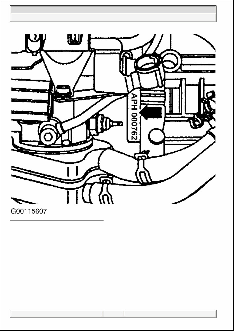
Engine identification number is stamped on a machined pad on front of engine block, below cylinder head,
where engine and transaxle mate together. See Fig. 1 . In addition there is a sticker on the valve with engine
code and engine serial number. Engine code is also included on the vehicle data plate.
ENGINE CODES 1.8L TURBO
NOTE: For engine repair procedures not covered in this article, see ENGINE
OVERHAUL PROCEDURES article in the GENERAL INFORMATION.
Model En g ine Code
2000-01
Golf AWD & AWW
GTI AWD & AWW
Jetta AWD & AWW
2002
Beetle AWP
GTI AWP
Jetta AWP
2001 Volkswagen GTI GLS
1.8L 4-CYLINDER 5-VALVE TURBO
1 января 2005 г . 1:25:33 Page 1 © 2004 Mitchell Repair Information Company, LLC.
Fig. 1: Locating Engine Identification Number
Courtesy of VOLKSWAGEN UNITED STATES, INC.
PROGRAMMING
After any repair which required that the battery be disconnected, the following should be performed. Refer
to owners manual for additional information.
1. Ensure ignition switch is in OFF position. Reconnect battery positive cable first then connect the
negative ground strap.
2. After connecting battery, enter anti-theft code for radio (if equipped).
3. Full y close all p ower windows, o p erate each window door switch in u p p osition for at least one
NOTE: When battery is disconnected, vehicle computer and memory systems may
lose memory data. Driveability problems may exist until computer systems
have completed a relearn cycle.
2001 Volkswagen GTI GLS
1.8L 4-CYLINDER 5-VALVE TURBO
1 января 2005 г . 1:25:35 Page 2 © 2004 Mitchell Repair Information Company, LLC.
second (windows closed) to activate "one touch" opening/closing function (if equipped).
4. Set clock to correct time.
ADJUSTMENTS
ACCELERATOR PEDAL
For testing and matching engine electronics control module to throttle valve control module. See
THROTTLE VALVE CONTROL MODULE (J338) in appropriate SELF-DIAGNOSTICS article in
ENGINE PERFORMANCE.
VALVE CLEARANCE
Engine is equipped with non-adjustable, non-serviceable hydraulic valve adjusters. Irregular valve adjuster
noise during cranking is normal. If valve adjuster(s) are noisy under any other condition inspect valve
adjusters. See HYDRAULIC VALVE ADJUSTERS .
HYDRAULIC VALVE ADJUSTERS
Checking
1. Start engine and run until cooling fan cycles at least once. Increase engine speed to 2500 RPM for 2
minutes or test drive vehicle and observe valve train noise. If valve train noise is still considered
noisy, go to next step.
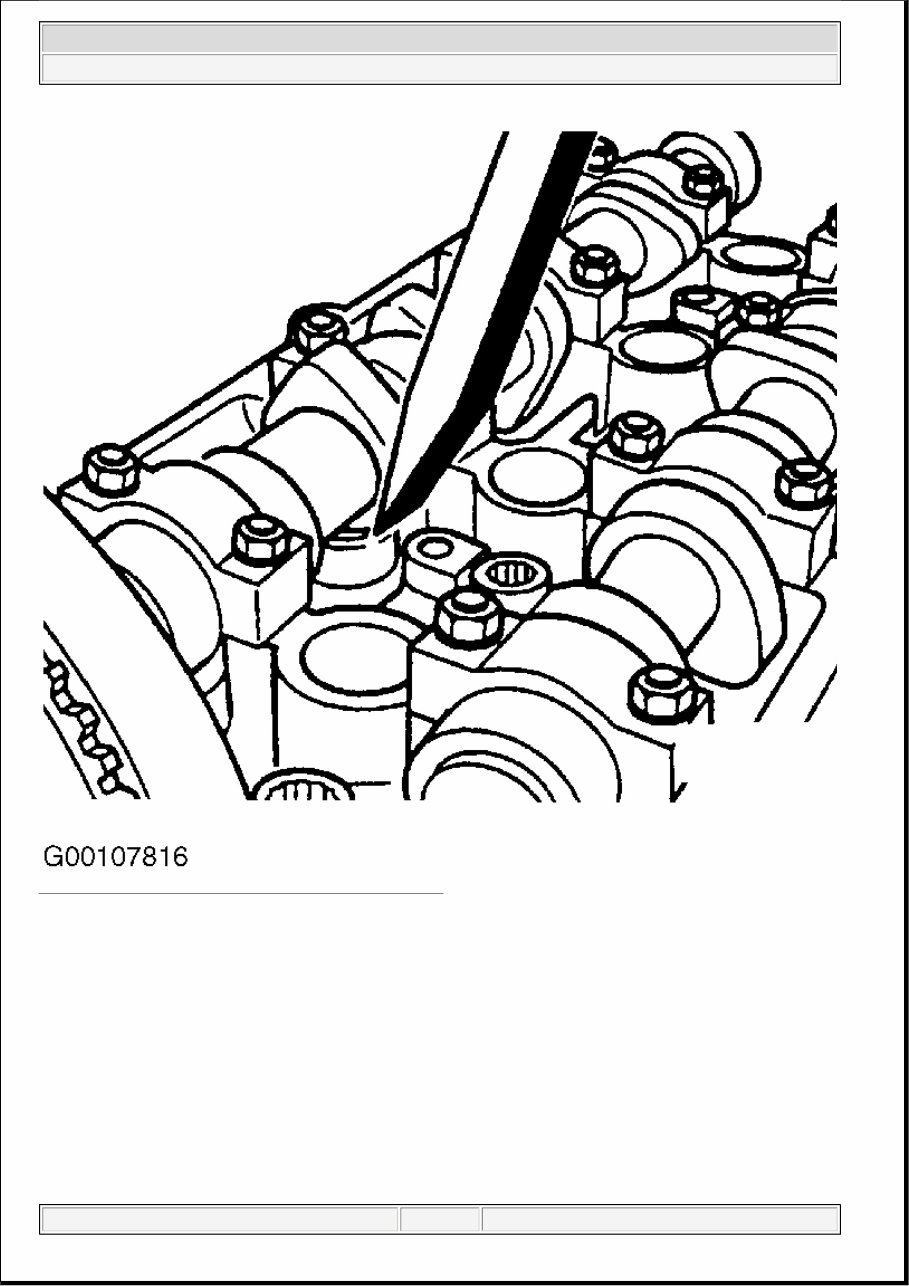
2. Turn engine off. Remove valve cover. Rotate crankshaft until camshaft lobes point upward on lifter
being checked. Using a wooden or plastic wedge, push down on top of lifter. See Fig. 2 . Try inserting
a .008" (.20 mm) feeler gauge between top of lifter and camshaft. If feeler gauge fits between top of
lifter and camshaft, re p lace fault y lifter.
NOTE: A drive by wire throttle system is used on this model vehicle. No throttle
cable adjustment required.
WARNING: ALWAYS release fuel pressure before disconnecting fuel injection related
component. DO NOT allow fuel to contact engine or electrical components.
CAUTION: DO NOT start engine for about 30 minutes after installing camshafts.
Hydraulic valve lifters must bleed down or valves may strike pistons. Rotate
crankshaft by hand 2 full revolutions before starting engine to ensure valves
do not strike pistons.
NOTE: Valve lifters are not repairable or adjustable. Replace faulty lifters. Irregular
valve train noise is normal when starting engine.
2001 Volkswagen GTI GLS
1.8L 4-CYLINDER 5-VALVE TURBO
1 января 2005 г . 1:25:35 Page 3 © 2004 Mitchell Repair Information Company, LLC.
Fig. 2: Placement Of Wedge On Lifter (Push Down)
Courtesy of VOLKSWAGEN UNITED STATES, INC.
TROUBLESHOOTING
To trouble shoot mechanical engine components, see appropriate table in TROUBLE SHOOTING article in
GENERAL INFORMATION.
REMOVAL & INSTALLATION
CAUTION: Radio/cassette or radio/CD player is equipped with an anti-theft protection
circuit. Whenever battery is disconnected, radio will go into anti-theft mode.
When battery is reconnected, radio will display CODE, and will be
inoperative until proper code number is entered. Obtain security code before
2001 Volkswagen GTI GLS
1.8L 4-CYLINDER 5-VALVE TURBO
1 января 2005 г . 1:25:35 Page 4 © 2004 Mitchell Repair Information Company, LLC.
FUEL PRESSURE RELEASE
Remove fuel pump relay located in fuse/relay panel (behind left side of dash). Start engine, allow engine to
run until it stops. Turn ignition off. Disconnect negative battery cable. Install fuel pump relay. Slight
p ressure may remain in system. Before disconnecting any fuel system line, cover connector with a clean
shop towel.
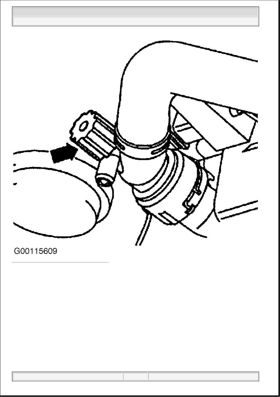
COOLING SYSTEM BLEEDING
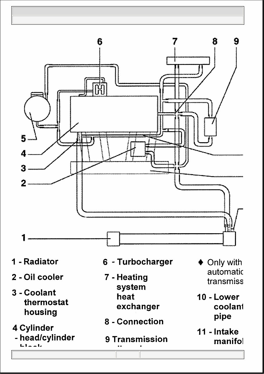
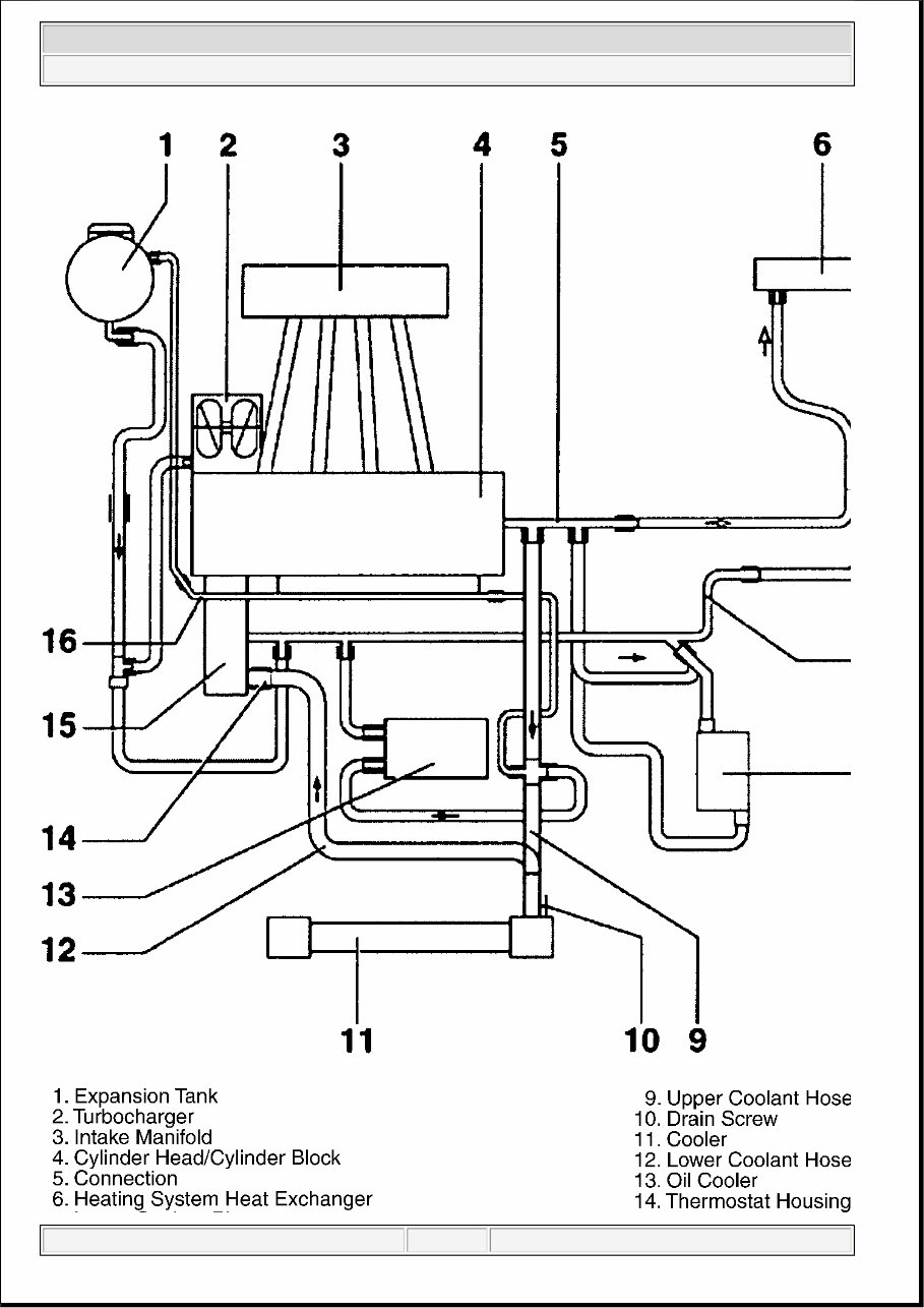
1. Ensure coolant drain valve is closed and all hoses are secure. See Fig. 3 and Fig. 4 . For help in
identifying components and component locations, refer to illustration. See Fig. 5 and Fig. 6
2. Fill expansion tank to proper level. Fill to Max mark on expansion tank (up to 2001 models) or to
upper portion of shaded area on expansion tank (2002 models). Install expansion tank cap. See Fig. 7
and Fig. 8 .
3. Put heater controls in Off position. Start engine and raise engine speed to 2000 RPM for about 3
minutes. Ensure cooling fan cycles on and off. Return engine to idle. Check coolant level in expansion
tank. With engine at normal operating temperature, coolant should be at the Max mark indicated on
expansion tank. Once engine has completely cooled, coolant should be between Max and Low marks.
Add coolant as necessar y .
disconnecting battery.
NOTE: When battery is disconnected, vehicle computer and memory systems may
lose memory data. Driveability problems may exist until computer systems
have completed a relearn cycle.
NOTE: For reassembly reference, label all electrical connectors, vacuum hoses and
fuel lines before removal. Place mating marks on other major assemblies
before removal.
2001 Volkswagen GTI GLS
1.8L 4-CYLINDER 5-VALVE TURBO
1 января 2005 г . 1:25:35 Page 5 © 2004 Mitchell Repair Information Company, LLC.
Fig. 3: Draining Coolant From Radiator
Courtes y of VOLKSWAGEN UNITED STATES, INC.
2001 Volkswagen GTI GLS
1.8L 4-CYLINDER 5-VALVE TURBO
1 января 2005 г . 1:25:35 Page 6 © 2004 Mitchell Repair Information Company, LLC.
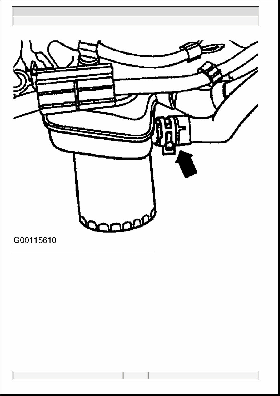
Fig. 4: Draining Coolant From Engine Block At Oil Cooler
Courtes y of VOLKSWAGEN UNITED STATES, INC.
2001 Volkswagen GTI GLS
1.8L 4-CYLINDER 5-VALVE TURBO
1 января 2005 г . 1:25:35 Page 7 © 2004 Mitchell Repair Information Company, LLC.
2001 Volkswagen GTI GLS
1.8L 4-CYLINDER 5-VALVE TURBO
1 января 2005 г . 1:25:35 Page 8 © 2004 Mitchell Repair Information Company, LLC.
Fig. 5: Identifying Cooling System Components & Hose Routing (AWD)
Courtes y of VOLKSWAGEN UNITED STATES, INC.
2001 Volkswagen GTI GLS
1.8L 4-CYLINDER 5-VALVE TURBO
1 января 2005 г . 1:25:35 Page 9 © 2004 Mitchell Repair Information Company, LLC.
2001 Volkswagen GTI GLS
1.8L 4-CYLINDER 5-VALVE TURBO
1 января 2005 г . 1:25:35 Page 10 © 2004 Mitchell Repair Information Company, LLC.
You're Reading a Preview
What's Included?
Lifetime Access
Access PDF Contents & Bookmarks
Print one or all pages of your manual