WISCONSIN VH4D Engine Workshop Service Repair & Parts Manual
What's Included?
Lifetime Access
Fast Download Speeds
Offline Viewing
Access Contents & Bookmarks
Full Search Facility
Print one or all pages of your manual
WISCONSIN MODEL VH4D V H D ILLUSTRATED CATALOG Wisconsin Motors, LLC 10 Industrial Drive P. O. BoxC Dyer, TN38330
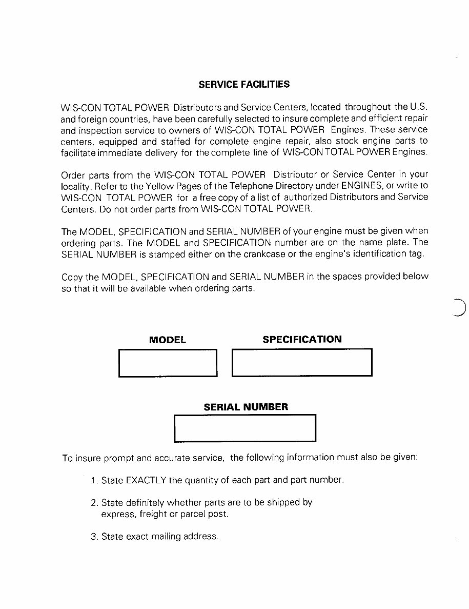
SERVICE FACILITIES WIS-CON TOTAL POWER Distributors and Service Centers, located throughout the U.S. and foreign countries, have been carefully selected to insure complete andefficient repair and inspection service to owners of WIS-CON TOTAL POWER Engines. These service centers, equipped and staffed for complete engine repair, also stock engine parts to facilitate immediate delivery for the complete line of WlS-CON TOTAL POWER Engines. Order parts from the WlS-CON TOTAL POWER Distributor or Service Center in your locality. Refer to the Yellow Pages of the Telephone Directory under ENGINES, or write to WIS-CON TOTAL POWER for a free copy of a list of authorized Distributors and Service Centers. Do not order parts from WIS-CON TOTAL POWER. The MODEL, SPECIFICATION and SERIAL NUMBER of your engine must be given when ordering parts. The MODEL and SPECIFICATION number are on the nameplate. The SERIAL NUMBER is stamped either on the crankcaseor the engine’s identification tag. Copy the MODEL, SPECIFICATION and SERIALNUMBER in the spaces provided below so that it will be available when ordering parts. MODEL I SPECIFICATION SERIAL NUMBER I To insure prompt and accurate service, I the following information mustalso be given: 1. State EXACTLY the quantity of each part and part number. 2. State definitely whether parts are to be shipped by express, freight or parcel post. 3. State exact mailing address.
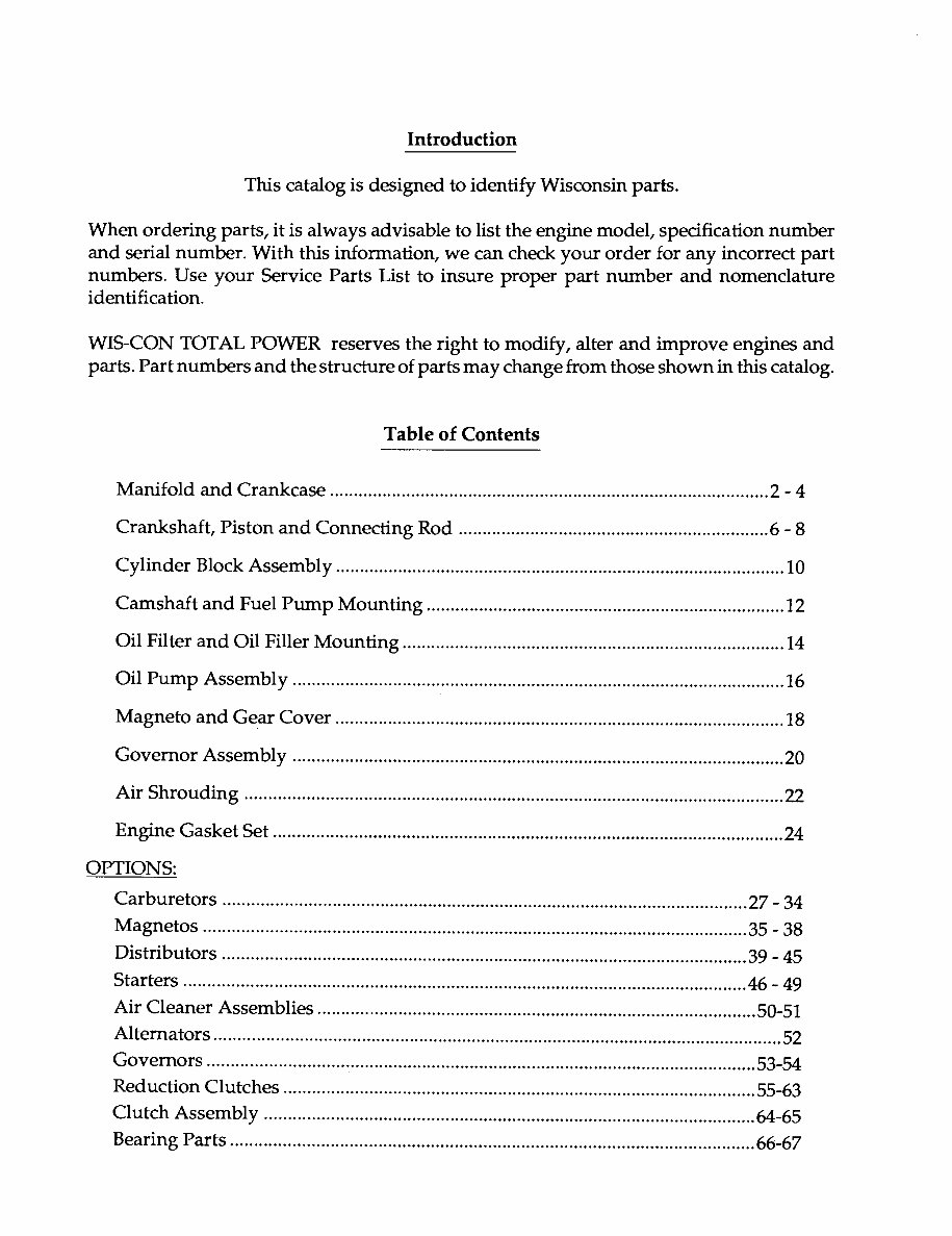
Introduction This catalog is designed to identify Wisconsinparts. When ordering parts, it is always advisable to list the engine model, specification number and serial number. With this information, we can check your order for any incorrect part numbers. Use your Service Parts List to insure proper part number and nomenclature identification.. WIS-CON TOTAL POWER reserves the right to modify, alter and improve engines and parts. Part numbersand the structure of parts maychange from those shown in this catalog. Table of Contents Manifold and Crankcase ............................................................................................ 2 - 4 Crankshaft, Piston and Connecting Rod ................................................................. 6 - 8 Cylinder Block Assembly .............................................................................................. 10 Camshaft and Fuel Pump Mounting ........................................................................... 12 OilFilterand OilFiller Mounting ................................................................................ 14 Oil Pump Assembly ....................................................................................................... 16 Magneto and Gear Cover .............................................................................................. 18 Governor Assembly ....................................................................................................... 20 Air Shrouding ................................................................................................................. 22 Engine Gasket Set ........................................................................................................... 24 OPTIONS: Carburetors .............................................................................................................. 27 - 34 Magnetos .................................................................................................................. 35 - 38 Distributors .............................................................................................................. 39 - 45 Starters ...................................................................................................................... 46 - 49 Air Cleaner Assemblies ............................................................................................ 50-51 Alternators ....................................................................................................................... 52 Governors ................................................................................................................... 53-54 Reduction Clutches ................................................................................................... 55-63 Clutch Assembly ....................................................................................................... 64-65 Bearing Parts .............................................................................................................. 66-67
3
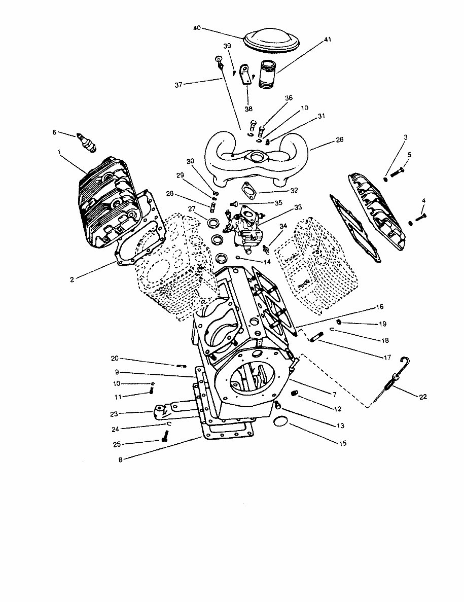
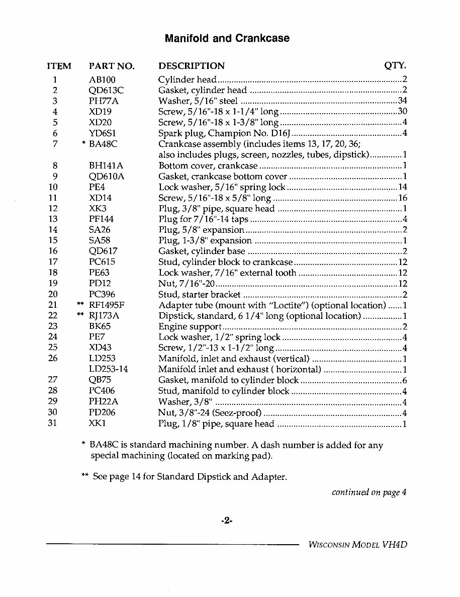
Manifold and Crankcase ITEM 1 2 3 4 5 6 7 8 9 10 11 12 13 14 15 16 17 18 19 20 21 22 23 24 25 26 27 28 29 30 31 PART NO. AB100 QD613C PH77A XD19 XD20 YD6S1 BA48C BH141A QD610A PE4 XD14 XK3 PF144 SA26 SA58 QD617 PC615 PE63 PD12 PC396 RF1495F RJ173A BK65 PE7 XD43 LD253 LD253-14 QB75 PC406 PH22A PD206 XK1 DESCRIPTION QTY. Cylinder head ................................................................................ 2 Gasket, cylinder head .................................................................. 2 Washer, 5 / 16" steel .................................................................... 34 Screw, 5/16"-18 x 1-1/4" long ................................................... 30 Screw, 5/16"-18 x 1-3/8" long ..................................................... 4 Spark plug, Champion No. D16J ................................................ 4 Crankcase assembly (includes items 13, 17, 20, 36; also includes plugs, screen, nozzles, tubes, dipstick) .............. 1 Bottom cover, crankcase .............................................................. 1 Gasket, crankcase bottom cover ................................................. 1 Lock washer, 5/16" spring lock ............................................ .... 14 Screw, 5/16"-18 x 5/8" long ...................................................... 16 Plug, 3/8" pipe, square head ...................................................... 1 Plug for7/16"-14 taps .................................................................. 4 Plug, 5/8" expansion .................................................................... 2 Plug, 1-3 / 8"expansion ................................................................ 1 Gasket, cylinder base ................................................................... 2 Stud, cylinder block to crankcase ............................................. 12 Lock washer, 7/16" external tooth ........................................... 12 Nut, 7/16"-20 ............................................................................... 12 Stud, starter bracket ..................................................................... 2 Adapter tube (mount with "Locfite") (optional location) ...... 1 Dipstick, standard, 6 1/4" long (optional location) ................. 1 Engine support .............................................................................. 2 Lock washer, 1/2"spring lock .................................................... 4 Screw, 1/2"-13 x 1-1/2" long ....................................................... 4 Manifold, inlet and exhaust (vertical)....................................... 1 Manifold inlet andexhaust (horizontal) .................................. 1 Gasket, manifold to cylinder block ............................................ 6 Stud, manifold to cylinder block ................................................ 4 Washer, 3/8". ................................................................................ 4 Nut, 3/8"-24 (Seez-proof) ............................................................ 4 Plug, 1/8" pipe, square head ...................................................... 1 * BA48C is standard machining number. A dash number is added for any special machining (located on marking pad). ** See page 14 for Standard Dipstick and Adapter. continued on page 4 -2- WISCONSIN MODEL VH4D
This workshop service manual is a comprehensive guide for WISCONSIN VH4D engine repair and parts. It is designed to meet the needs of WISCONSIN technicians worldwide, providing detailed information on the 30 HP Gasoline, Dual Fuel (LPG and NG options), Four Cylinder, Air Cooled engine with V-Block configuration. The manual covers components such as the forged-steel crankshaft with tapered roller main bearings, heavy-duty cast-iron block, forged steel connecting rod, cast iron cylinders, centrifugal flyball type governor, exhaust valve rotators, aluminum alloy pistons, heat resistant alloy steel exhaust valves, replaceable valve seat inserts, and solid-state ignition. This manual is invaluable for both professional mechanics and DIY enthusiasts.
Recently Viewed
5,521,897Happy Clients
2,594,462eManuals
1,120,453Trusted Sellers
15Years in Business
Price:
Actual Price:
WISCONSIN VH4D Engine Workshop Service Repair & Parts Manual