

TECUMSEH TVT691 V TWIN Engine Full Service & Repair Manual
What's Included?
Fast Download Speeds
Online & Offline Access
Access PDF Contents & Bookmarks
Full Search Facility
Print one or all pages of your manual
V-TWIN
ENGINE
TECUMSEH

i
TABLE OF CONTENTS
CHAPTER 1. GENERAL INFORMATION
CHAPTER 2. AIR CLEANERS
CHAPTER 3. CARBURETORS AND FUEL SYSTEMS
CHAPTER 4. GOVERNORS AND LINKAGE
CHAPTER 5. ELECTRICAL SYSTEMS
CHAPTER 6. IGNITION
CHAPTER 7. INTERNAL ENGINE AND DISASSEMBLY
CHAPTER 8. ENGINE ASSEMBLY
CHAPTER 9. TROUBLESHOOTING AND TESTING
CHAPTER 10. ENGINE SPECIFICATIONS
Copyright © 2000 by Tecumseh Products Company
All rights reserved. No part of this book may be reproduced or transmitted, in any form or by any
means, electronic or mechanical, including photocopying, recording or by any information storage and
retrieval system, without permission in writing from Tecumseh Products Company Training Department
Manager.

ii
TABLE OF CONTENTS
(by subject)
GENERAL INFORMATION
Page
Engine Identification ................................................................................................ 1-1
Interpretation of Engine Identification ...................................................................... 1-1
Short Blocks ............................................................................................................ 1-2
Fuels ........................................................................................................................ 1-2
Engine Oil ................................................................................................................ 1-3
Basic Tune-Up Procedure ....................................................................................... 1-4
Storage .................................................................................................................... 1-4
AIR CLEANERS
General Information ................................................................................................. 2-1
Operation ................................................................................................................. 2-1
Components ............................................................................................................ 2-1
Troubleshooting and Testing .................................................................................... 2-1
Service ..................................................................................................................... 2-2
CARBURETORS AND FUEL SYSTEMS
General Information ................................................................................................. 3-1
Float Style Carburetors ............................................................................................ 3-1
Operational Circuits Series 7 Carburetor ................................................................. 3-1
Testing ..................................................................................................................... 3-3
Carburetor Disassembly Procedure ........................................................................ 3-5
Inspection ................................................................................................................ 3-7
Carburetor Re-Assembly ......................................................................................... 3-7
Throttle Shaft and Plate ................................................................................... 3-7
Choke Shaft and Plate ..................................................................................... 3-8
Fuel Bowl Assembly ........................................................................................ 3-8
Impulse Fuel Pumps ................................................................................................ 3-9
Impulse Fuel Pump Service ........................................................................... 3-10
GOVERNORS AND LINKAGE
General Information ................................................................................................. 4-1
Operation ................................................................................................................. 4-1
Troubleshooting ....................................................................................................... 4-1
Engine Speed Adjustments ..................................................................................... 4-1
Engine Overspeed ........................................................................................... 4-2
Engine Surging ................................................................................................ 4-2
Governor Service
Static Adjustment - Governor .......................................................................... 4-2
Governor Gear and Shaft Service ................................................................... 4-3
Governor Shaft Replacement .......................................................................... 4-3

iii
Page
Speed Controls and Linkage ................................................................................... 4-3
Synchronizing the Carburetors ................................................................................ 4-4
Choke Synchronization ............................................................................................ 4-5
ELECTRICAL SYSTEMS
General Information ................................................................................................. 5-1
Operation ................................................................................................................. 5-1
Converting Alternating Current to Direct Current ..................................................... 5-2
Components
Battery ............................................................................................................ 5-2
Wiring .............................................................................................................. 5-2
Condition ......................................................................................................... 5-2
Wire Gauge ..................................................................................................... 5-2
Electrical Terms ....................................................................................................... 5-3
Basic Checks ........................................................................................................... 5-3
Charging Circuit ....................................................................................................... 5-4
3 Amp D.C. 5 Amp A.C. Alternator ......................................................................... 5-4
Diode Replacement ........................................................................................ 5-4
Checking the System ...................................................................................... 5-5
16 Amp Alternator System with External Regulator ................................................. 5-5
Troubleshooting Electrical Charging Circuit Flow Chart .......................................... 5-6
Voltage Regulators .................................................................................................. 5-7
Fuel Shut-Down Solenoids ...................................................................................... 5-7
Low Oil Pressure Sensor Testing ............................................................................. 5-7
Starting Circuit ......................................................................................................... 5-8
Testing Procedure Starting Circuit .................................................................. 5-8
Troubleshooting Electrical Starter Circuit Flow Chart ..................................... 5-9
Electric Starter Service .......................................................................................... 5-10
12 Volt Electric Starter .................................................................................. 5-10
Inspection and Repair ................................................................................... 5-11
Brush Holder ................................................................................................. 5-12
Brush Replacement ...................................................................................... 5-12
IGNITION
General Information ................................................................................................. 6-1
Operation
Solid State Ignition System (CDI) ............................................................................ 6-1
Components .................................................................................................... 6-1
Testing Procedure ............................................................................................ 6-2
Service
Spark Plug Service .......................................................................................... 6-3
Conditions Causing Frequent Spark Plug Fouling ........................................... 6-3
Ignition Timing ......................................................................................................... 6-3
Service Tips ............................................................................................................. 6-4
TABLE OF CONTENTS (continued)

iv
INTERNAL ENGINE AND DISASSEMBLY
General Information ................................................................................................. 7-1
Lubrication Systems ................................................................................................ 7-1
Disassembly Procedure ........................................................................................... 7-1
Disassembly of Cylinder Heads ............................................................................... 7-4
Valves .............................................................................................................. 7-5
Valve Guides ................................................................................................... 7-5
Valve Springs ................................................................................................... 7-6
Push Rods ....................................................................................................... 7-6
Valve Seats ...................................................................................................... 7-6
Internal Engine Component Inspection
Cylinders .......................................................................................................... 7-7
Pistons ............................................................................................................. 7-8
Rings ............................................................................................................... 7-9
Connecting Rods ........................................................................................... 7-10
Crankshafts and Camshafts .......................................................................... 7-11
Mechanical Compression Release ................................................................ 7-12
Valve Lifters ................................................................................................... 7-13
Crankcase Breather ....................................................................................... 7-13
Cylinder Cover ............................................................................................... 7-13
ENGINE ASSEMBLY
Engine Assembly ..................................................................................................... 8-1
TROUBLESHOOTING AND TESTING
Engine Knocks ......................................................................................................... 9-1
Engine Overheats .................................................................................................... 9-1
Surges or Runs Unevenly ........................................................................................ 9-1
Engine Misfires ........................................................................................................ 9-1
Engine Vibrates Excessively .................................................................................... 9-2
Breather Passing Oil ................................................................................................ 9-2
Excessive Oil Consumption ..................................................................................... 9-2
Lack Power .............................................................................................................. 9-2
ENGINE SPECIFICATIONS
TVT691 Engine Specifications ............................................................................... 10-1
Torque Specifications ............................................................................................ 10-3
Service Tool List .................................................................................................... 10-4
TABLE OF CONTENTS (continued)
Page
1-1
1-1
CHAPTER 1. GENERAL INFORMATION
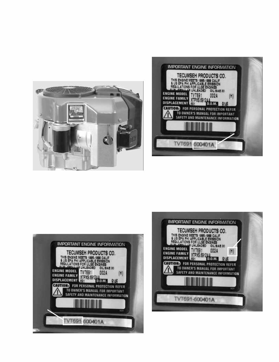
ENGINE IDENTIFICATION
Tecumseh engine model, specification, and date of
manufacture (D.O.M.) are located on decals attached to
the blower housing of the engine. The engine
identification decal also provides the applicable warranty
code, oil and fuel recommendations, EPA (Environmental
Protection Agency) and C.A.R.B. (California Air Resource
Board) Emission Compliance Information. (Illust. 1-1)
The group of numbers following the model number is
the specification number. The last three numbers
indicate a variation to the basic engine specification.
(Illust. 1-3)
INTERPRETATION OF ENGINE
IDENTIFICATION
The letter designations (TVT) in a model number
indicate the basic type of engine.
The number designations following the letters (691)
indicate the basic engine model displacement in CC’s
(cubic centimeters). (Illust. 1-2)
1-2
The letter in parenthesis on the engine information decal
is the warranty code identification number. This letter
designates the length of time the engine is under
warranty. A cross-reference may be found in the service
warranty policy of the master repair manual or the engine
operator’s manual. (Illust. 1-4)
1-3
1-4
ENGINE
MODEL
NUMBER
SPECIFICATION
NUMBER
WARRANTY
IDENTIFICATION
NUMBER

1-2
The D.O.M. (date of manufacture) indicates the
production date of the engine by year and numerical day.
(Illust. 1-5)
This symbol points out important safety
INSTRUCTIONS, WHICH IF NOT FOLLOWED,
could endanger the personal safety of YOU and
others. Follow all instructions.
SHORT BLOCKS
New short blocks are identified by a tag marked S.B.V.
(Short Block Vertical) located on the engine block. When
a short block repair is made, it is vital both the original
engine and short block numbers are present on the
repaired product for correct future parts identification.
(Illust. 1-6)
1-5
1-6
Using model TVT691-600401A D.O.M. 9146 as an
example, the interpretation is as follows:
TVT691- Is the model number.
60041A Represents the specification number used for
properly identifying the parts of the engine.
TVT Tecumseh Vertical Twin.
691 Indicates the displacement in cubic
centimeters.
9146 Is the D.O.M. (Date of Manufacture) formerly
serial number.
9 Is the last digit in the year of manufacture
(1999).
146 Indicates the calendar day of that year (146th
day or May 26
th
of 1999).
A,B,C A letter following the D.O.M. number
represents the line, shift and plant in which
the engine was built.
Emissionized engines that meet the California Air
Resource Board (C.A.R.B.) or the Environmental
Protection Agency (EPA) standards will include additional
required engine information on the engine decal.
NOTE: To maintain the best possible emission
performance, use only Genuine Tecumseh Parts.
FUELS
Tecumseh Products Company strongly recommends the
use of fresh, clean, unleaded regular gasoline in all
Tecumseh engines. Unleaded gasoline burns cleaner,
extends engine life, and promotes good starting by
reducing the build up of combustion chamber deposits.
Unleaded regular, unleaded premium or reformulated
gasoline containing no more than 10% Ethanol, 15%
MTBE or 15% ETBE may be used.
Leaded fuel is not available in the United States and
should not be used if any of the above options are
available.
Never use gasoline, fuel conditioners, additives or
stabilizers containing methanol, white gas, or fuel blends,
which exceed the limits, specified above for Ethanol,
MTBE, or ETBE because engine/fuel system damage
could result.
CAUTION: THE USE OF SOME ANTI-ICING
ADDITIVES MAY CREATE A METHANOL FUEL
BLEND. DO NOT USE ADDITIVES THAT
CONTAIN METHANOL. FUEL CONDITIONERS
THAT CONTAIN ISOPROPYL ALCOHOL CAN
BE USED IN CORRECT MIXTURE RATIOS.
Regardless of which of the approved fuels are used, fuel
quality is critical to engine performance. Fuel should
not be stored in an engine or container more than 30
days prior to use. Time may be extended with the use of
a fuel stabilizer like TECUMSEH, part number 730245.
See “STORAGE” instructions in this Manual, Operators
Manual, or Bulletin 111.
DATE OF
MANUFACTURE
(D.O.M.)
SBV OR SBH IDENTIFICATION NUMBER
SHORT BLOCK IDENTIFICATION TAG
SERIAL NUMBER
SBV- 564A
SER 5107
1-3
Change oil and filter after the first two operating hours.
Standard oil change intervals are every 50 hours. Oil
filter changes are recommended every 100 operating
hours.
Oil Change Intervals: Change the oil and filter after
the first 2 hours of operation. Thereafter oil change
intervals are every 50 hours. Oil and oil filter changes
are requested every 100 operating hours. Service should
be performed more often if operated under extremely
dusty or dirty conditions. The oil and filter (if equipped)
should be changed yearly if operated less than 100 hours.
Oil Check: Check the oil each time the equipment is
used or every five-(5) hours of operation. Position the
equipment so the engine is level when checking the oil
level.
CAUTION: A TWIN CYLINDER ENGINE MAY
START AND RUN ON ONLY ONE CYLINDER.
ALWAYS DISCONNECT BOTH SPARK PLUG
WIRES FROM THE SPARK PLUGS AND
GROUND TO THE DEDICATED RETAINING
POSTS LOCATED ON THE VALVE COVER
BOXES BEFORE ATTEMPTING ANY SERVICE
OR MAINTENANCE WORK ON THE ENGINE OR
EQUIPMENT.
ENGINE OIL
TECUMSEH FOUR-CYCLE ENGINES REQUIRE THE
USE OF CLEAN, HIGH QUALITY DETERGENT OIL.
Be sure original container is marked: A.P.I. service “SF”
thru “SJ” or “CD”.
TECUMSEH RECOMMENDS USING ONE OF THE
FOLLOWING FOUR CYCLE OILS THAT ARE
SPECIALLY FORMULATED TO TECUMSEH
SPECIFICATIONS.
DO NOT USE SAE 10W40 OIL.
FOR SUMMER (Above 32
0
F) (0
o
C) USE SAE 30 OIL.
PART 730225
Use SAE 30 oil in high temperature, high load
applications. Using multigrade oil may increase oil
consumption.
FOR WINTER (Below 32
0
F) (0
o
C) USE SAE 5W30 OIL.
PART 730226
(SAE 10W is an acceptable substitute.)
(BELOW 0
0
F (-18
o
C) ONLY): SAE 0W30 is an
acceptable substitute.
Oil Capacity
Engine Model oz. ml.
TVT691 with Filter 80 2366
TVT691 Oil Only 72 2129
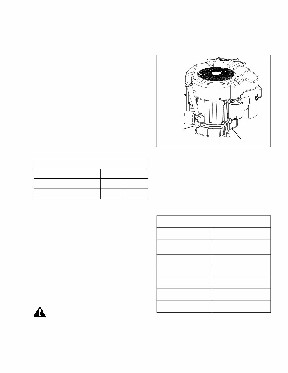
Oil Change Procedure: Locate the oil drain plug in the
mounting flange. The drain plug or cap on most units is
located above the frame in one of the locations shown.
(Illust. 1-7) The oil filter if equipped, can be removed
with a commercially available filter wrench.
NOTE: An oil change is best performed after the engine
is warm.
Remove the oil plug or cap and allow the oil to drain into
a proper receptacle. Always make sure that drain oil and
filter are disposed of properly. Contact your local
governing authorities to find a waste oil disposal site.
Once the oil is drained, reinstall the drain plug and fill the
engine with new oil to the proper capacity.
BASIC MAINTENANCE CHART
Pre-filter (Dry Poly) Clean every 25 hours
Air filter (Paper Element) Replace every 100 hours of
operation
Oil change Every 50 hours or annually
Oil filter Every 100 hours or
annually
Spark plug replacement Every 100 hours or
annually
Clean cooling fins Every 200 hours or
annually
Fuel Filter (Replace) Every 100 hours or
annually
1-7 STANDARD OIL DRAIN PLUG LOCATION
ALTERNATE
LOCATION
1-4
1-8
BASIC TUNE-UP PROCEDURE:
NOTE: Today’s fuels can cause many problems in an
engines performance due to the fuel quality and short
shelf life (as little as 30 days). Always check fuel as a
primary cause of poor engine performance before
performing any other service.
The following is a minor tune-up procedure. When this
procedure is completed, the engine should operate
properly. Further repairs may be necessary if the engine’s
performance remains poor.
CAUTION: REMOVE THE SPARK PLUG WIRES
AND ATTACH TO THE DEDICATED RETAINING
POSTS BEFORE DOING ANY SERVICE WORK
ON THE ENGINE.
1. Service or replace the air cleaner. See Chapter 2
under “Service”.
2. Inspect the level and condition of the oil, change or
add oil as required.
3. Remove the blower housing and clean all dirt, grass
or debris from the intake screen, Cylinder head,
cooling fins, carburetor, governor levers and linkage.
4. Check that the fuel filter, fuel tank, and fuel line are
clean. We recommend replacing the fuel filter every
100 hours or annually.
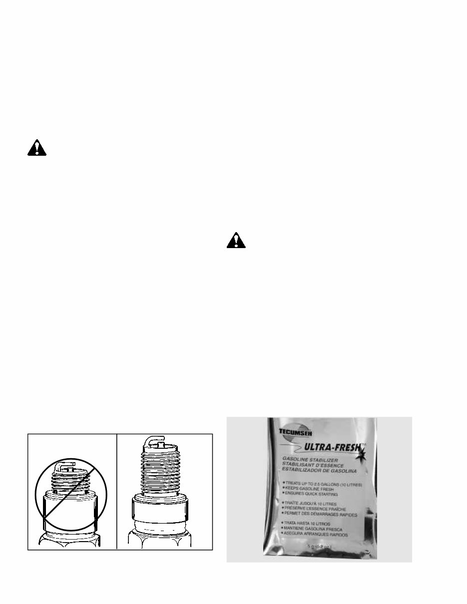
5. Replace the spark plugs every 100 hours or annually,
consult the parts breakdown for the correct spark
plug to be used. Set the spark plug gap (.030") (.762
mm) and install the plug, being careful not to cross
thread. Tighten the spark plug to 21 foot pounds
(28 Nm) of torque. If a torque wrench is not
available, turn the spark plug in as far as possible
by hand, then use a spark plug wrench to turn the
plug 1/2 turn further. If installing a used plug, only
1/8 to 1/4 turn after seat is needed. Note: The correct
plug reach must be used see (Illust. 1-8).
6. Make sure all ignition wires are free of abrasions or
breaks and are properly routed so they will not rub
on the flywheel.
7. Completely clean the cooling fins, intake screen and
linkages of all dirt and debris. Reinstall the blower
housing, fuel tank, fuel line, and air cleaner assembly
if removed. Be careful not to pinch any of the
wires upon re-assembly.
8. Make sure all remote cables are correctly routed and
adjusted for proper operation. See Chapter 4, under
“Speed Controls and Linkage”.
9. Reinstall the spark plug wires, add fuel and oil as
necessary, start the engine.
STORAGE
(IF THE ENGINE IS TO BE UNUSED FOR 30 DAYS
OR MORE)
CAUTION: NEVER STORE THE ENGINE WITH
FUEL IN THE TANK INDOORS OR IN
ENCLOSED, POORLY VENTILATED AREAS,
WHERE FUEL FUMES MAY REACH AN OPEN
FLAME, SPARK OR PILOT LIGHT AS ON A
FURNACE, WATER HEATER, CLOTHES
DRYER OR OTHER GAS APPLIANCE.
Gasoline can become stale in less than 30 days and
form deposits that can impede proper fuel flow and engine
operation. To prevent deposits from forming, all gasoline
must be removed from the fuel tank and the carburetor.
An acceptable alternative to removing all gasoline, is by
adding Tecumseh fuel stabilizer, part number 730245,
to the gasoline. Fuel stabilizer is added to the fuel tank
or storage container. Always follow the mix ratio found
on the stabilizer container. Run the engine at least 10
minutes after adding the fuel stabilizer to allow it to
reach the carburetor. (Illust. 1-9)
1-9
STANDARD
PLUG
OHV
2-1
2-1
CHAPTER 2. AIR CLEANERS
GENERAL INFORMATION
The air cleaner is the device used to eliminate dust and
dirt from the air supply. Filtered air is necessary to assure
that abrasive particles are removed before entering the
combustion chamber. Dirt allowed into the engine will
quickly wear the internal components and shorten engine
life.
The TVT series engine uses a paper-type air filter system
and also has a dry foam pre-filter.
Extremely dirty conditions require more frequent pre-filter
cleaning or paper element replacement.
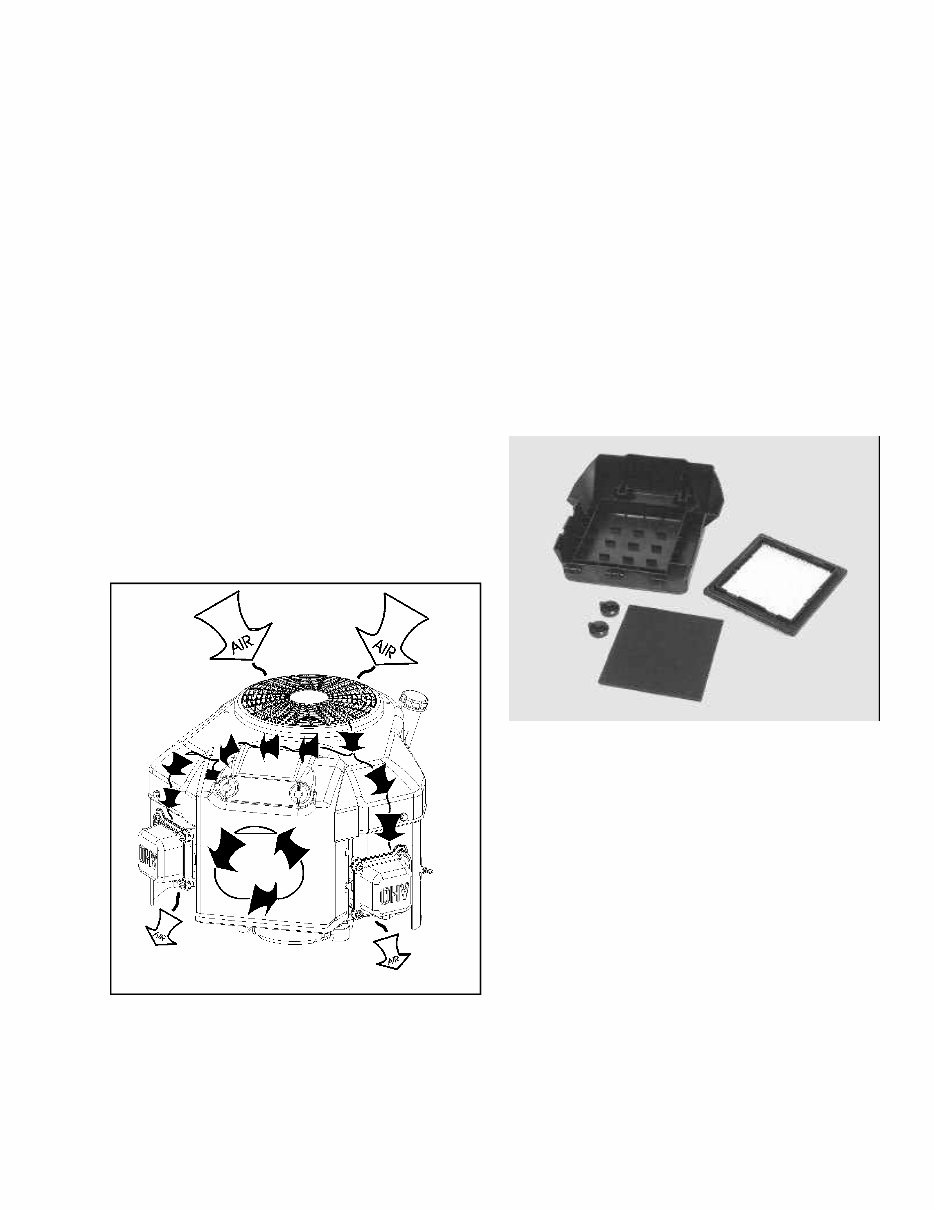
OPERATION
The air filter cover secures and seals the paper filter
element in place. The cover also prevents large particles
from entering the filter body and completes the Kleen-
Aire
®
circuit. The air is first filtered through the flywheel
and blower housing then enters the air filter cover. It
travels through the pre-filter then the paper filter element.
Pre-filters typically extend the paper filter life.
(Illust. 2-1)
COMPONENTS
The cover holds the poly pre-cleaner and clamps the
paper filter in place, creating a dirt tight seal. The cover
also prevents large debris from entering the filter body.
The pre-cleaner is made of a polyurethane foam and
designed to pre-filter the air prior to it passing through
the paper filter. This added stage, assures the operator
of maximum air filtering and extends paper filter life.
The paper filter element is the main filter to stop
impurities from entering the engine. This dry-type element
is pleated paper for increased surface area maximizing
its life. The filter has rubberized edges to assure sealing.
(Illust. 2-2)
TROUBLESHOOTING AND TESTING
If the engine’s performance is unsatisfactory (runs
unevenly, starts smoking abnormally or loses power),
the first engine component(s) to be checked are the air
filter(s). A dirt restricted or oil soaked filter will cause
noticeable performance problems. Polyurethane pre-filter
can be cleaned following the service procedure listed
under “Service” in this chapter. A paper-type air filter can
only be replaced NEVER attempt to clean a paper filter.
The paper-type filter must not have any oil film or residue
present. Should the paper have a brown tint it may have
been damaged by an excessively oiled pre-filter or
crankcase breather problems. Follow the procedure listed
in the “Service” section of this chapter for filter
replacement or cleaning.
2-2
You're Reading a Preview
What's Included?
Fast Download Speeds
Online & Offline Access
Access PDF Contents & Bookmarks
Full Search Facility
Print one or all pages of your manual
$31.99
Viewed 17 Times Today


Secure transaction
What's Included?
Fast Download Speeds
Online & Offline Access
Access PDF Contents & Bookmarks
Full Search Facility
Print one or all pages of your manual
$31.99
- This complete factory service repair workshop manual is available for instant access on your computer, tablet, or smartphone.
- It covers all repairs, servicing, and troubleshooting procedures with detailed photos and diagrams.
- Professional mechanics and technicians use this manual, which contains step-by-step instructions and highly detailed exploded diagrams and pictures.
- You have the option to print out a single page or the entire manual.
- This manual can be used on multiple computers without any limitations or trial periods.
- There is no expiry date or renewal fee; you can use this manual for life.
- It is fully compatible with Windows and MAC computers.
For more information, please click the button below.


