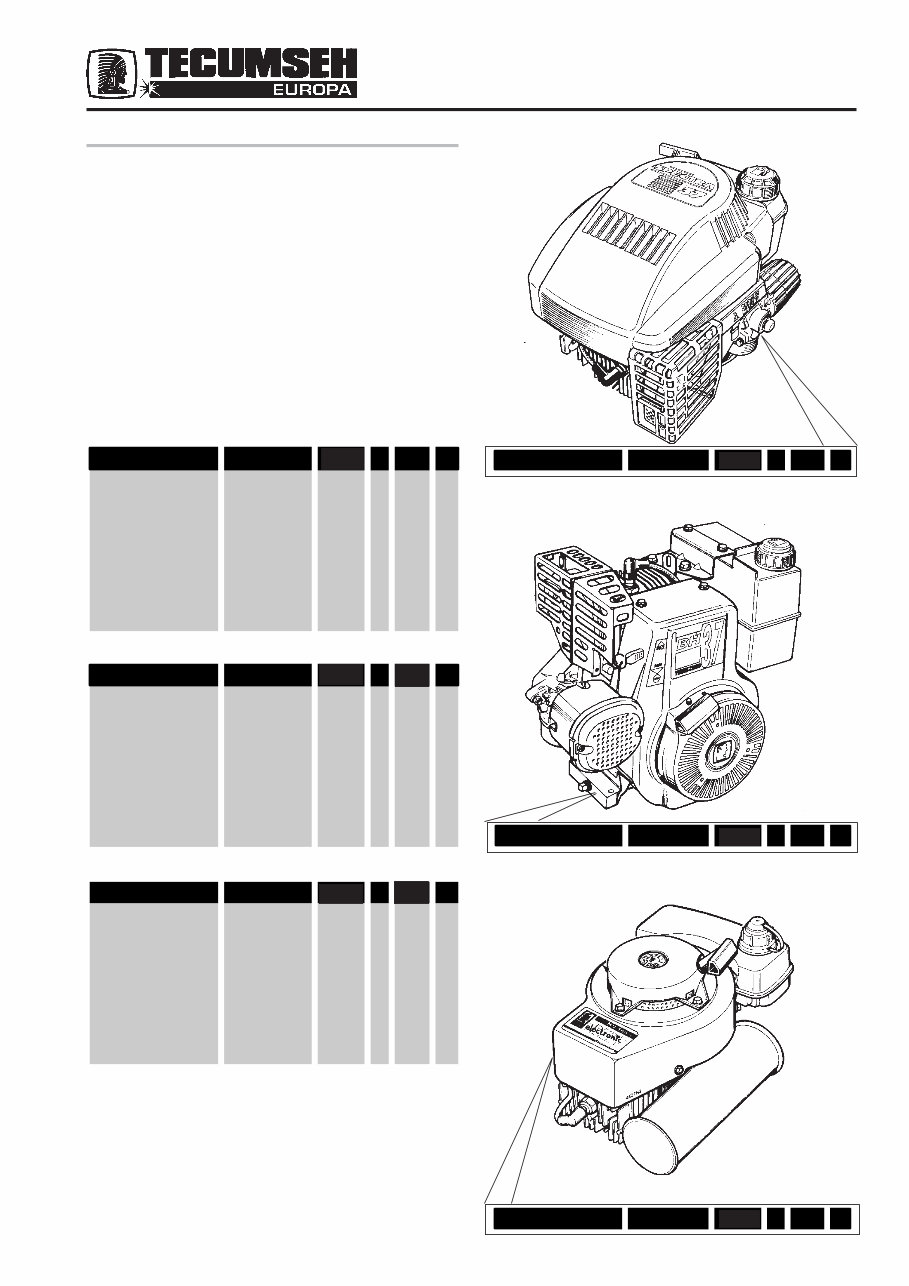
2 BH 37 E-45040E SER 5 174 C A. FOREWORD This manual contains information required to service or repair all Tecumseh Italian built engines. For exploded views of particular engines or component part numbers, refer to the Tecnamotor and Tecumseh Europa Spare Parts Catalogue. When ordering spares from your authorized Tecumseh Dealer, please quote the entire model and specification number. These numbers are stamped on the engine as shown below. Always insist on genuine Tecumseh replacement parts. ENGINE CODE SPECTRA 37 E-38000 5 174 A MODELLO SPECIFICA NUMERO DI SERIE ANNO DI COSTR. GIORNO DI COSTR. TURNO BH 37 E-45040E 5 074 C MODELLO SPECIFICA NUMERO DI SERIE ANNO DI COSTR. GIORNO DI COSTR. TURNO MV 100 S E-16000C 5 074 C MODELLO SPECIFICA NUMERO DI SERIE ANNO DI COSTR. GIORNO DI COSTR. TURNO SPECTRA 37 E-38000 5 174 A MV 100 S E-16000C 5 174 C S S S S S S 174 174
SERVICE BULLETIN Subject: 2-stroke engines - running in and oil requirements Tecumseh now requires that all 2-stroke engines with a recommended fuel/oil mix greater than 25 : 1 should be run with the first tank of fuel mixed at double the recommended ratio. This gives increased protection during the piston ring seating process. We also highly recommend the use of Tecumseh smokeless oil (part number 26980003), which is an extremely high quality and environmentally friendly product. The use of alternative oils which may be of a lower quality will invalidate the warranty. 70/A
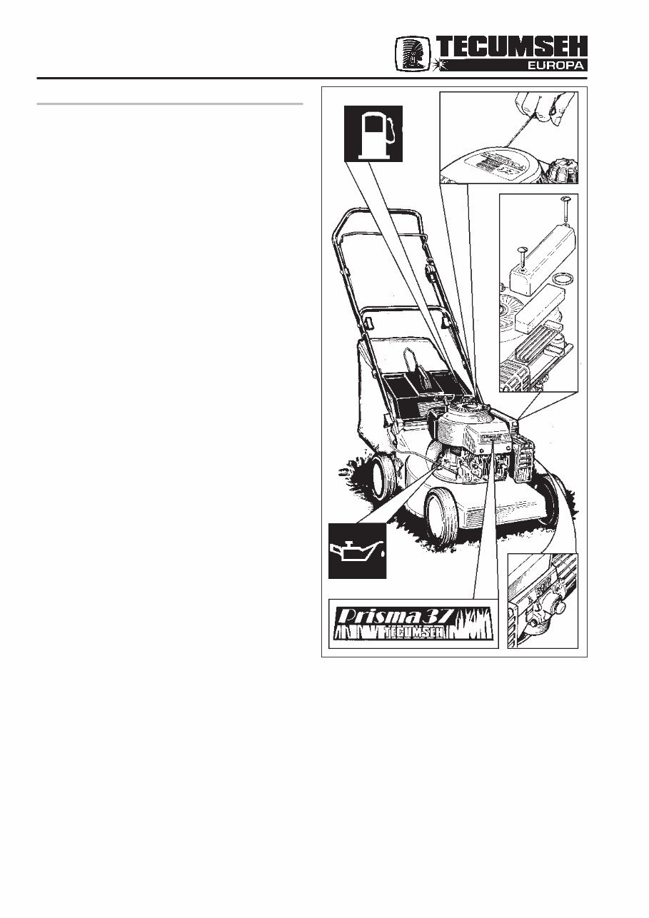
3 Fig. 1 B. CHECK-UP BEFORE REPAIR 1. GENERAL If a customer complains of an engine “non-starting”, it is a good rule to make an accurate check by first pulling the starter to ensure that there are no internal breakages. Ascertain that the correct fuel/oil mixture is being used. (2-stroke engines). Check the carburettor and governor controls, remote control, air cleaner, spark plug, oil level (4-stroke engines). Drain and refill fuel tank with fresh, clean fuel. For 2-stroke engines, AV and MV, use a 4% (25:1) or 2% (50:1) petrol/oil mixture. Refer to the operator's manual for correct mix for each engine. USE CLEAN FRESH FUEL FOR TESTING NOTE - If engine is fitted with remote control and choke, check that: - With the lever in the choke or start position, the choke is fully closed and the throttle open. This is important for starting from cold. - With the lever in the max position, make sure that the throttle is fully open. If full throttle is not being attained, maximum power will not be obtained from the engine.
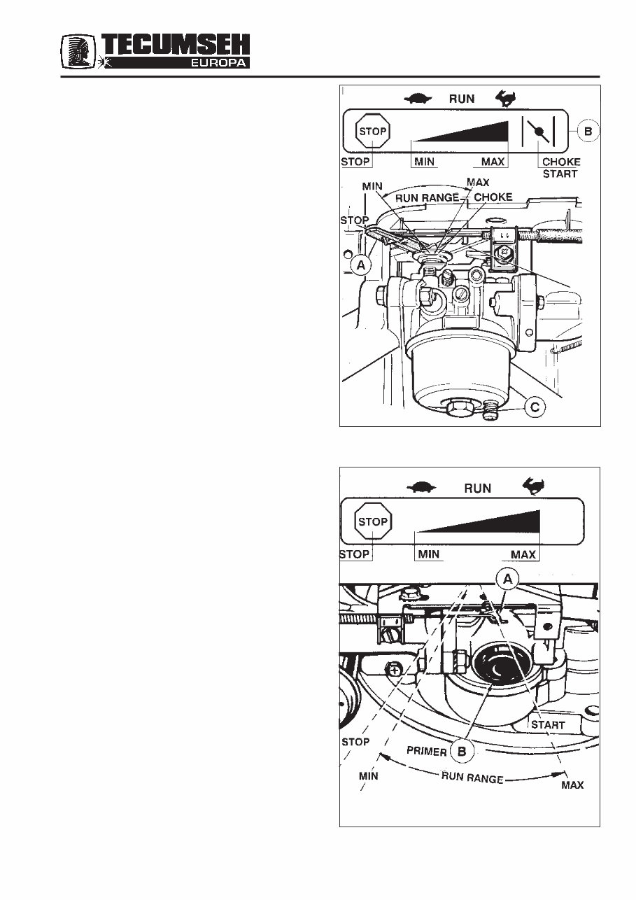
4 2. RECOIL STARTER (CHOKE) a - Move control lever (Fig 2) on engine or remote control (Fig 2) on equipment to choke or start. b - Operate mower control to release engine brake (if any). c - Pull starter handle (Fig 2-2) with a quick firm action. Allow the rope to recoil back into its housing whilst retaining grip on handle. d - Repeat preceding instructions B and C until engine starts. Then gradually move control lever on engine or remote control on equipment away from choke or start to max position. NOTE - If engine fires, but fails to start, move control lever on engine or remote control on equipment to MAX position and repeat preceding instructions B and C until engine starts. NOTE - Warm engine normally starts without choking. Move control lever (Fig 2) on engine or remote control (Fig 2) on equipment to MAX position; then follow ‘b’ ‘c’ and ‘d’ instructions. RECOIL STARTER (PRIMER) a - Move control lever (Fig 2-1) to “FAST” or “START” (see equipment manufacturer’s instructions). b - Push primer (Fig 2-1) three (3) times. Wait about two (2) seconds between each push. In cold weather (55F/ 13°C or below) push five (5) times. NOTE - Do not use primer to restart a warm engine c - Operate mower control to release engine brake (if any). d - Grasp starter handle (Fig 2-2) and slowly pull rope out until a slight resistance is felt. Let rope rewind slowly. Then pull rope with a rapid full arm stroke. NOTA - If engine fails to start after three (3) pulls, repeat instructions ‘b’, ‘c’ and ‘d’. Fig. 2 Fig. 2-1
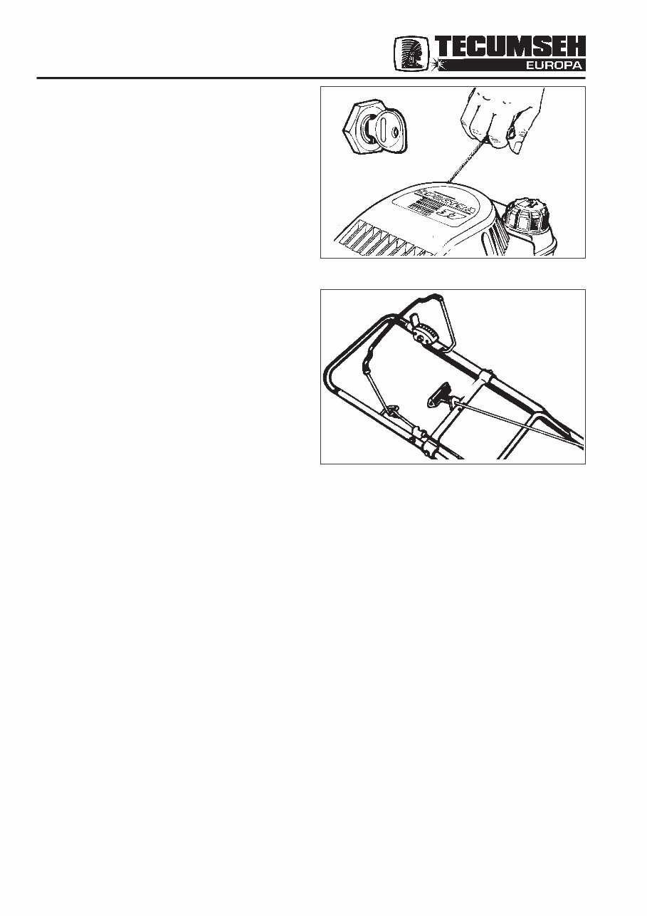
5 RECOIL STARTER (PRIMER FIXED SPEED) a - Push primer (Fig 2.1) three (3) times. Wait about two (2) seconds between each push. In cold weather (55°F/13°C or below) push five (5) times. NOTE - Do not use primer to restart a warm engine. b - Operate mower control to release engine brake. c - Grasp starter handle (Fig 3) and slowly pull rope out until a slight resistance is felt. Let rope rewind slowly. Then pull rope with a rapid full arm stroke. NOTE - If engine fails to start after three (3) pulls, repeat instructions ‘a’,’b’ and ‘c’. If the engine starts and runs satisfactorily, the customer should be instructed on starting and maintenance procedure, otherwise continue engine fault check. ELECTRIC STARTER ( Fig 2-2) To start engine with electric start option, follow the above procedure except use the key to activate the starter motor. NOTE - Ensure engine has stopped rotating before re- engaging the starter motor. 3. CHECK-UP A general systematic check can usually locate the fault in a matter of minutes. The following five points cover this operation: - Starter - Compression - Ignition - Carburetion - Equipment a) STARTER Pull starter and ensure that the starter dog engages and turns the engine. If not, see chapter C, Starter Repair Methods, ensure that the rope has not been shortened, thus reducing the number of starting revolutions. The compression may also be checked by this operation. Fig. 2-2 Fig. 3
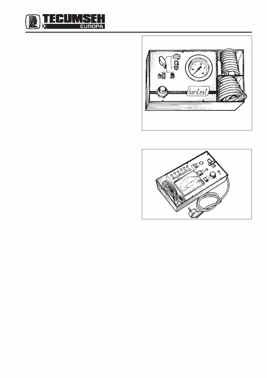
6 b) COMPRESSION If compression is poor, check for: - Flywheel slipping on crankshaft. - Loose spark plug. - Loose cylinder head bolts. - Damaged cylinder head. - Warped cylinder head. - Insufficient tappet clearance (4-stroke engines). - Broken connecting rod. - Loose or worn crankshaft seals (2-stroke). If engine is fitted with compression release, it is necessary to remove cylinder head and check components visually if a leak tester is not available. NOTE - With the compression leak tester faults can be found easily within minutes (Fig 4). c) IGNITION Remove spark plug and connect a new one to the HT lead, earth plug body to cylinder head, turn the engine and check that a strong spark occurs between the plug electrodes. If no spark occurs see chapter E for service and repair instructions. If spark occurs, fit new spark plug and attempt to start engine. Remember that spark failure can also be due to such faults as: - Broken flywheel key. - Crankshaft bearing worn, thus preventing cam from opening (breaker point ignition). - Incorrect air gap setting (electronic ignition). NOTE - When using the compression leak tester ( Fig 4) and the ignition tester (Fig 5), faults may quickly be located. If no fault can be found, the defect must be within the carburation system or the equipment. Fig. 4 Compression Leak Tester. Tests for leakage of valves, rings and cylinder head in situ. Fig. 5 Tests standard ignition system in situ. Solid state units must be removed for test. d) CARBURATION After having drained and cleaned fuel tank, refill with fresh fuel and check (float carburettors) that fuel flows from the bowl when the drain valve is pressed. On diaphragm carburettors without primer, remove high speed jet and operate diaphragm. Fuel should then flow from jet seat. If fuel does not flow, check fuel line and filters, re-set carburettor as in chapter G and carry out starting procedure. If engine still fails to start, remove sparking plug and pour a small quantity of fuel into the cylinder, replace sparking plug and attempt to start. If engine fires a few times it may be assumed that the carburettor is at fault. Check completely the carburettor as in chapter G. Fig. 4 Fig. 5
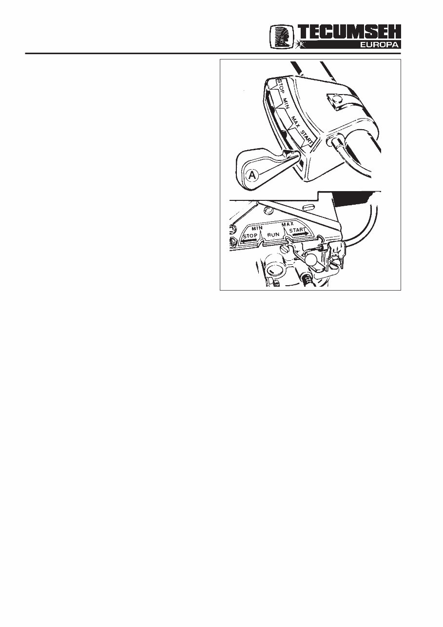
7 NOTE - On 2-stroke engines a broken or damaged reed plate will prevent starting. e) EQUIPMENT What may initially appear to be an engine fault, such as a starting difficulty or engine vibration, may possibly be the fault of the equipment rather than the engine. Owing to the great number of machines in use, it is not possible to list these separately. The following is a list of the more common problems: Hard Starting, Kickback, Failure to Start - Loose blade. The blade must be tight on shaft or adaptor. - Loose belt. A loose belt, as with a loose blade, can cause a backlash effect which will counteract the engine cranking effort. - Starting under load; ascertain that the equipment is disengaged if the unit has a heavy starting load. - Check remote control assy for proper adjustment with the lever A in choke or start position. The carburettor choke should be fully closed (Fig 6). - Grass cuttings building up under deck may cause difficulties. Clean deck. - Check that grass collectors are empty. An overfilled collector could cause engine malfunction. Vibration - Damaged or out of balance blade - Damaged or out of balance impellor - Loose mounting bolts, engine to deck - Worn blade mounting; replace if mounting allows blade to move causing unbalance. Noise - Cutter blade coupling or pulley, an oversize or worn coupling can result in knocking, particularly under acceleration. Check for fit and tightness. Fig. 6 A
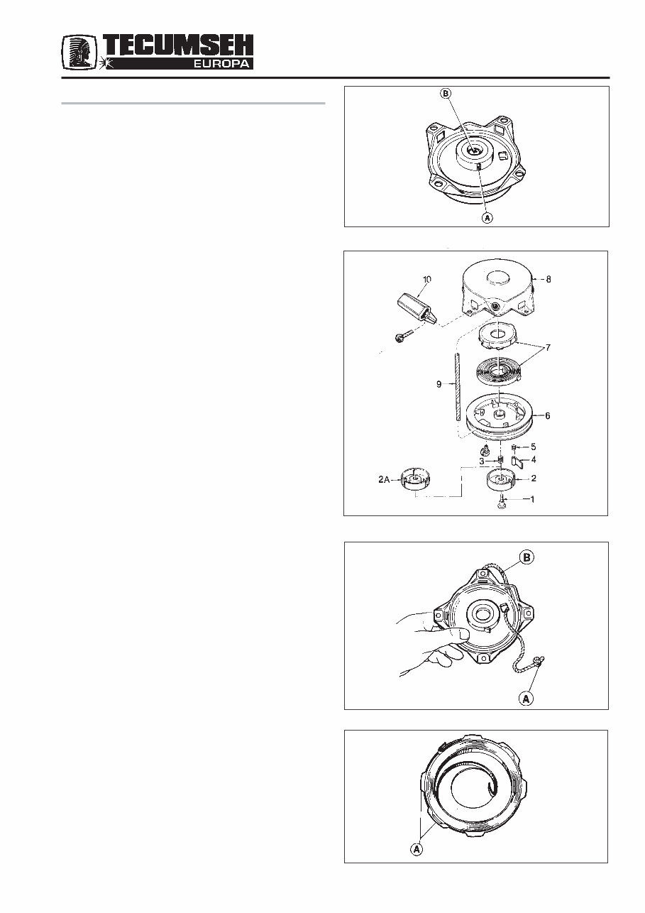
8 C. STARTER NON-STYLIZED STARTERS LAV - BV - BVS - VANTAGE - HBL - BH - AV - MV 1. RECOIL STARTER In the event of starter failure, remove the unit from the engine and check the following items: - That dog A (Fig 1) protrudes when the rope is slowly pulled. If the rope cannot be pulled, check the retainer hub locking screw B for correct tightening torque, which should be kgm 0.5 - 0.6 (45/55 inch lbs). - If, after correct tensioning of screw B (Fig 1), the dog does not function, disassemble the starter as follows, referring to exploded view shown in Fig 2. Fig 2 - Exploded View Standard Top Starter 1. Retaining Screw 2. Retainer 3. Brake Spring 4. Dog 5. Dog Return Spring 6. Rope Pulley 7. Rewind Spring 8. Starter Housing 9. Rope 10. Handle To disassemble starter Release spring tension. Slightly extend rope and lock pulley . Untie knot or remove staple securing handle and release pulley (Fig 3). - Remove centre locking screw. - Remove retainer hub, brake spring and dog. - Remove dog return spring B, bearing in mind its position for correct replacement. (Fig 6). - Remove pulley and spring container assembly. - Once the damaged parts have been replaced, lubricate spring container with soft grease (Fig 4) and proceed with reassembly. Fig. 1 Fig. 4 Fig. 2 Fig. 3
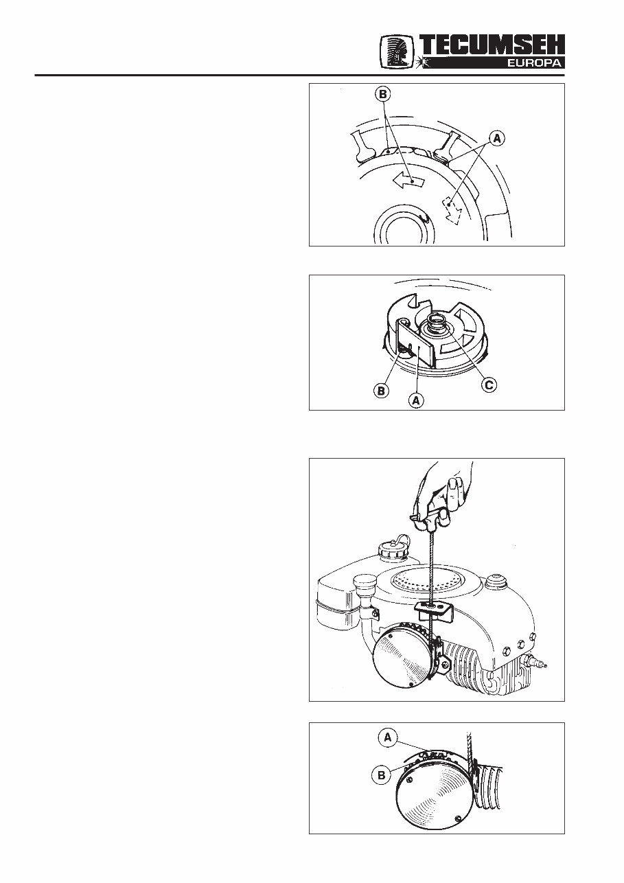
9 To reassemble starter - Accurately position spring container on pulley (Fig 5). - Reposition the pulley assembly into container lubricating shaft and bushing of plastic pulley. Fig. 5 A. Spring Engagement B. Spring Disengagement - Refit retainer spring, place dog and brake spring in position (Fig 6). - Accurately position retainer hub and secure with the screw. - Re-tension recoil spring. - Wind pulley clockwise until tight, then allow to unwind until the hole in the pulley lines up with the eyelet in the housing. Lock pulley. Install rope and handle. Tie knot in rope to secure to pulley. Release pulley. (Fig 3). - After reassembling starter, always make sure that by pulling the rope slightly the starter dog operates, and that the rope can be fully extended. When released, the handle should be held firmly against the starter housing. - The correct tension of the spring is obtained after approximately 5 turns of the pulley. 2. SIDE MOUNTED STARTER HORIZONTAL ENGAGEMENT TYPE (LAV, BV) The side mounted starter was developed for use on machines in which engines are mounted in a low position. (Fig 7). Fig 8 - System of Engagement A. Flywheel gear B. Pulley gear The starter operates the engine by engaging a gear into teeth on the underside of flywheel. (Fig 8). When the engine starts, the flywheel speed disengages the starter gear. Fig. 5 Fig. 6 Fig. 7 Fig. 8
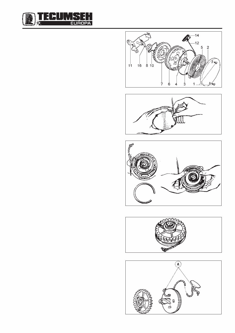
10 Disassembly Disassemble starter as follows. Refer to Fig 9. - Release main spring tension (5) by removing the handle and sliding the rope (12) out of the rope clip (16). (Fig 10). - Remove rope clip and replace if necessary. - Remove the two screws (1) and spring cover (2). The spring (5) may be replaced at this point without further disassembly. - Carefully remove old spring and place new spring com- plete with keeper in position and push spring into place in the container. (Fig 11). - For further disassembly remove central fixing screw (3) and remove pulley assy. (Fig 12). - Remove brake spring (10) and washer (8) - only early type starters, and separate gear (7) from pulley (6). If necessary, replace rope (12) referring to Fig 13. - Untie knots A and remove rope from handle (14) and pulley (6). - Fit a new rope of the same dimensions and retie knots. - Check all parts before reassembly. Fig. 13 Fig. 12 Fig. 11 Fig. 10 Fig. 9
This service repair manual covers the Tecumseh Europa Italian built engine models:
Spectra 37
BH37
MV100 S
It provides comprehensive step-by-step information on repair, servicing, and preventative maintenance. The manual is highly detailed with photos and illustrations to assist in every repair and troubleshooting procedure. Whether you are a professional mechanic or a DIY enthusiast, this manual contains all the necessary information to keep your Tecumseh Engine in optimal condition.
Repairing a Tecumseh engine at home can be cost-effective and rewarding. This official repair manual equips you with the necessary guidance and knowledge to undertake repairs with minimal time and space requirements.
Having a repair manual at hand offers the benefit of addressing simple and common problems associated with Tecumseh engines. It includes a troubleshooting section with various options for symptoms and corresponding repair methods, potentially saving significant costs and time.
The manual covers a wide range of topics including carburettor kits, oil filters, pistons, gaskets, brakes, chains, wheel bearings, tires, lamps, gearbox, throttle, electrical, suspension, exhaust, and much more.
For more complex repairs, the manual provides step-by-step instructions on disassembly, repair methods, and illustrations, empowering you to address issues with confidence and ease.
Bookmarked chapters facilitate easy navigation, allowing quick access to specific repair service procedures. Throughout each chapter, notes, cautions, and warnings highlight critical service information. Numbered instructions and bold figured numbers ensure a clear and structured approach to every repair procedure.
Detailed illustrations, exploded diagrams, drawings, and photos further guide you through each service repair procedure. The numbered table of contents enhances usability, enabling swift access to the required information.
Language: English
File Format: PDF
File Delivery: Instant
Pages: 109
To obtain this comprehensive repair manual, simply click on the green "Instant" button at the upper left-hand corner of this page. Upon purchase, download it to your computer for convenient access and printing whenever necessary.