

Tecumseh 8 to 18 hp Technician / Service Manual
What's Included?
Fast Download Speeds
Online & Offline Access
Access PDF Contents & Bookmarks
Full Search Facility
Print one or all pages of your manual

T E C H N I C I A N ' S H A N D B O O K
TECUMSEH
8 TO 18 HP
CAST IRON
FOUR CYCLE
ENGINES
This manual covers the following models:
VH80, VH100, HH80, HH100, HH120, OH120-180
Model numbers are located on the engine shroud.
Other illustrated Tecumseh 2-Cycle Engine, 4-Cycle Engine
and Transmission manuals; booklets; and wall charts are
available through Tecumseh.
For complete listing write or call

Contents
Page
CHAPTER 1. GENERAL INFORMATION ................................................................................................................................... 1
SECTION 1. ENGINE IDENTIFICATION ............................................................................................................................. 1
SECTION 2. ENGINE CARE ............................................................................................................................................... 2
CHAPTER 2. AIR CLEANERS, CARBURETORS, GOVERNORS AND LINKAGE ................................................................... 4
SECTION 1. AIR CLEANERS .............................................................................................................................................. 4
SECTION 2. GENERAL CARBURETOR INFORMATION .................................................................................................. 5
SECTION 3. TECUMSEH CARBURETORS ....................................................................................................................... 6
SECTION 4. WALBRO CARBURETORS .......................................................................................................................... 10
HH80 - 120, VH80 - 100 .............................................................................................................................................. 10
SECTION 5. OVERHEAD VALVE ENGINE CARBURETORS .......................................................................................... 13
SECTION 6. GOVERNORS ............................................................................................................................................... 16
SECTION 7. IMPULSE FUEL PUMP ................................................................................................................................. 19
CHAPTER 3. REWIND STARTERS, ELECTRIC STARTERS, TROUBLESHOOTING AND GENERATORS ......................... 20
SECTION 1. REWIND STARTERS .................................................................................................................................... 20
SECTION 2. ELECTRIC STARTERS ................................................................................................................................ 22
SECTION 3. 12 VOLT STARTER TROUBLE SHOOTING CHART ................................................................................... 25
CHAPTER 4. GENERAL VALVE INFORMATION, CYLINDER HEAD AND BREATHER ASSEMBLY ................................... 27
SECTION 1. GENERAL VALVE INFORMATION ............................................................................................................... 27
SECTION 2. CYLINDER HEAD ......................................................................................................................................... 31
SECTION 3. BREATHER ASSEMBLIES ........................................................................................................................... 32
CHAPTER 5. PISTON AND RINGS, CONNECTING RODS AND CRANKSHAFTS ................................................................ 33
SECTION 1. PISTON AND RINGS .................................................................................................................................... 33
SECTION 2. CONNECTING RODS ................................................................................................................................... 35
SECTION 3. CRANKSHAFTS ........................................................................................................................................... 36
CHAPTER 6. CAMSHAFT, BEARINGS AND SEALS ............................................................................................................... 37
SECTION 1. CAMSHAFT .................................................................................................................................................. 37
SECTION 2. BEARINGS .................................................................................................................................................... 38
SECTION 3. SEALS ........................................................................................................................................................... 42
CHAPTER 7. DYNA-STATIC
®
BALANCING SYSTEM ............................................................................................................. 43
CHAPTER 8. IGNITION SYSTEMS, CHARGING SYSTEMS BATTERY SERVICE and
ELECTRICAL CONTROL PANELS .......................................................................................................................................... 45
SECTION 1. IGNITION SYSTEMS .................................................................................................................................... 45
SECTION 2. CHARGING SYSTEMS ................................................................................................................................. 48
SECTION 3. BATTERY SERVICE ..................................................................................................................................... 53
SECTION 4. ELECTRICAL CONTROL PANELS .............................................................................................................. 56
CHAPTER 9. TROUBLESHOOTING ........................................................................................................................................ 61
CHAPTER 10. 8 H.P. & LARGER ENGINE SPECIFICATIONS AND TORQUES .................................................................... 66
SECTION 1. CROSS REFERENCE LIST FOR TABLE OF SPECIFICATIONS ................................................................ 66
SECTION 2. TORQUE SPECIFICATIONS ........................................................................................................................ 70
8 H.P. & LARGER ENGINES (EXCEPT VALVE-IN-HEAD) ......................................................................................... 70
SECTION 3. VALVE-IN-HEAD ENGINE SPECIFICATIONS ............................................................................................. 71
SECTION 4. TORQUE SPECIFICATIONS ........................................................................................................................ 73
VALVE-IN-HEAD .......................................................................................................................................................... 73
CHAPTER 11. EDUCATIONAL MATERIALS AND TOOLS ...................................................................................................... 74
i
C Tecumseh Products Company
1998
1
CHAPTER 1. GENERAL INFORMATION
SECTION 1. ENGINE IDENTIFICATION
Tecumseh engine model numbers are stamped into
the blower housing, or are located on a nameplate
or tag on the engine in locations as illustrated.
INTERPRETATION OF MODEL NUMBER. The first
letter designations in a model number indicate the
basic type of engine.
HH - Horizontal-Heavy Duty (Cast Iron)
VH - Vertical-Heavy Duty (Cast Iron)
OH - Overhead Valve-Heavy Duty (Cast Iron)
The number designations following the letter indicates
the horsepower of the engine.
The number following the model number is the
specification number. The last three numbers of the
specification number indicate a variation to the basic
engine specification.
The serial number indicates the production data.
Using model number OH160-170033, Serial 8044C
as an example, interpretation is as follows:
OH160-170033 - is the model and specification number.
OH - Overhead Valve-Heavy Duty (Cast Iron)
160 - Indicates 16 horsepower.
170033 - is the specification number used for properly
identifying the parts of the engine.
8044C - is the serial number.
8 - first digit is the year of manufacture (1998)
044 - indicates calendar day of that year (044 day
or February 13, 1998).
C - represents the line, shift or plant in which the
engine was built at the factory.
SHORT BLOCKS. New short blocks are identified
by a tag marked SBH (Short Block Horizontal) or
SBV (Short Block Vertical). Original model tags of
engines should always be transferred to a short block
for correct parts identification.
OH160-170033 SER 8044C

2
SECTION 2. ENGINE CARE
FUELS. Use clean, fresh unleaded automotive gasoline
in all Tecumseh four-cycle engines. (Leaded “regular”
gasoline is an acceptable substitute.)
NOTE: Do Not use gasoline containing methanol
(wood alcohol). Gasoline containing a maximum of
10 ethanol or grain alcohol (sometimes called “gasohol”)
may be used but requires special care when engine
is unused for extended periods.
See “STORAGE” instructions.
ENGINE OIL, ALL FOUR CYCLE ENGINES:
USE A CLEAN, HIGH QUALITY, DETERGENT OIL.
Be sure original container is marked with engine
service classification “SF - SJ.”
DO NOT USE SAE10W40 OIL.
FOR SUMMER (ABOVE 32°F, 0°C) USE SAE 30 OIL
(SAE10W30 is an acceptable substitute.)
FOR WINTER (BELOW 32°F, 0°C) USE SAE 5W20
OR 5W30 OIL.
(SAE10W is an acceptable substitute.)
(BELOW 0°F, -18°C ONLY) Use 0W30 oil or SAE10W
oil diluted with 10% kerosene is acceptable.
NOTE: For severe, prolonged, winter operation of
HH120 model, SAE10W oil is recommended.
OIL CHANGE INTERVALS. Change oil after first two
(2) hours of operation and every 25 hours thereafter,
or more often if operated under dusty or dirty conditions.
OIL CHECK. Check oil every 5 hours or each time
the equipment is used. Position equipment so the
engine is level when checking the oil.
BREAK-IN PROCEDURE. Proper break-in procedure
is important for proper seating of rings, on a new
engine or newly overhauled engine.
Do normal work with the unit, running the engine
under load. Vary the load on the engine frequently
to aid in seating of the rings.
The engine should not be allowed to idle or run at
part throttle for extended periods during break-in.
Work the engine but do not abuse it.
TUNE-UP PROCEDURE. The following is a minor
tune-up procedure. When this procedure is completed,
the engine will operate properly or you may discover
that further repairs may have to be performed.
NOTE: It is recommended to use only factory parts
in a Tecumseh engine. This is especially important
with an air filter, since the use of any other than the
specified part number may result in serious damage
to the engine.
CAUTION: Remove spark plug wire before doing
any service work on engine.
1. Service or replace air cleaner as necessary.
2. Inspect level and condition of oil; drain oil.
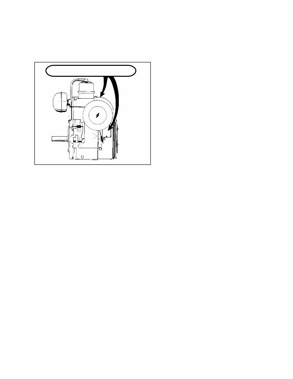
3. Remove blower housing, clean all dirt, grass or
debris from intake screen, head and cylinder cooling
fins and carburetor governor levers and linkage.
4. Remove cylinder head, remove carbon, inspect
valves and cylinder bore. Replace head using
a new head gasket. Torque to specifications.
5. Remove carburetor, clean and install carburetor
kit, make adjustment pre-sets where needed.
Make sure fuel tank, fuel filters and fuel lines
are clean. Reinstall carburetor, replacing any worn
or damaged governor springs or linkage. Make
proper governor adjustment.
6. Remove flywheel, check for leaks in oil seals,
check flywheel key and reinstall flywheel. Replace
spark plug and check for spark.
7. Make sure all remote linkage is properly adjusted
for proper operation.
8. Replace fuel and oil.
9. Run engine and adjust carburetor and set R.P.M.
to specifications found on Microfiche or computer
parts lookup.
STORAGE: (IF THE ENGINE IS TO BE UNUSED
FOR 30 DAYS OR MORE)
CAUTION: NEVER STORE THE ENGINE WITH
FUEL IN THE TANK INDOORS , IN ENCLOSED
POORLY VENTILATED AREAS WHERE FUEL
FUMES MAY REACH AN OPEN FLAME, SPARK
OR PILOT LIGHT AS ON A FURNACE, WATER
HEATER, CLOTHES DRYER OR OTHER GAS
APPLIANCE.
Gasoline can become unstable in less than 30 days
and form deposits that can impede proper fuel flow
and engine operation. To prevent deposits from forming,
all gasoline must be removed from the fuel tank and
the carburetor. An acceptable alternative to removing
all gasoline is adding a fuel stabilizer to the gasoline.
Fuel stabilizer (such as Tecumseh’s Part No. 730245)
is added to the fuel tank or storage container. Always
follow the mix ratio found on the stabilizer container.
Run the engine at least 10 minutes after adding the
stabilizer to allow it to reach the carburetor.

3
DRAINING THE FUEL SYSTEM:
CAUTION: DRAIN THE FUEL INTO AN
APPROVED CONTAINER OUTDOORS, AND
AWAY FROM ANY OPEN FLAME OR
COMBUSTION SOURCE. BE SURE THE
ENGINE IS COOL.
1. Remove all gasoline from the fuel tank by running
the engine until the engine stops, or by draining
the fuel tank by removing the fuel line at the
carburetor or fuel tank. Be careful not to damage
the fuel line, fittings, or fuel tank.
2. Drain the carburetor by pressing upward on the
bowl drain (if equipped) which is located on the
bottom of the carburetor bowl. On carburetors
without a bowl drain, the carburetor may be drained
by loosening the bowl nut on the bottom carburetor
one full turn. Allow to completely drain and retighten
the bowl nut being careful not to damage the
bowl gasket when tightening.
3. If "Gasohol" has been used, complete the above
procedure and then put one half pint of unleaded
gasoline into the fuel tank and repeat the above
procedure. If Gasohol is allowed to remain in
the fuel system during storage, the alcohol content
will cause rubber gaskets and seals to deteriorate.
Change Oil: If the oil has not been changed recently,
this is a good time to do it.
Oil Cylinder Bore:
1. Disconnect the spark plug wire and ground the
wire to the engine. Remove the spark plug and
put 1/2 ounce (14 ml) of clean engine oil into
the spark plug hole.
2. Cover the spark plug hole with a shop towel.
3. Crank the engine over slowly several times.
CAUTION: AVOID SPRAY FROM SPARK PLUG
HOLE WHEN SLOWLY CRANKING ENGINE
OVER.
4. Install the spark plug and connect the spark plug
wire.
Clean Engine: Remove the blower housing and clean
all dirt, grass or debris from the intake screen, cylinder
head, cylinder cooling fins, carburetor, governor levers
and linkage.
4
CHAPTER 2. AIR CLEANERS, CARBURETORS,
GOVERNORS AND LINKAGE
SECTION 1. AIR CLEANERS
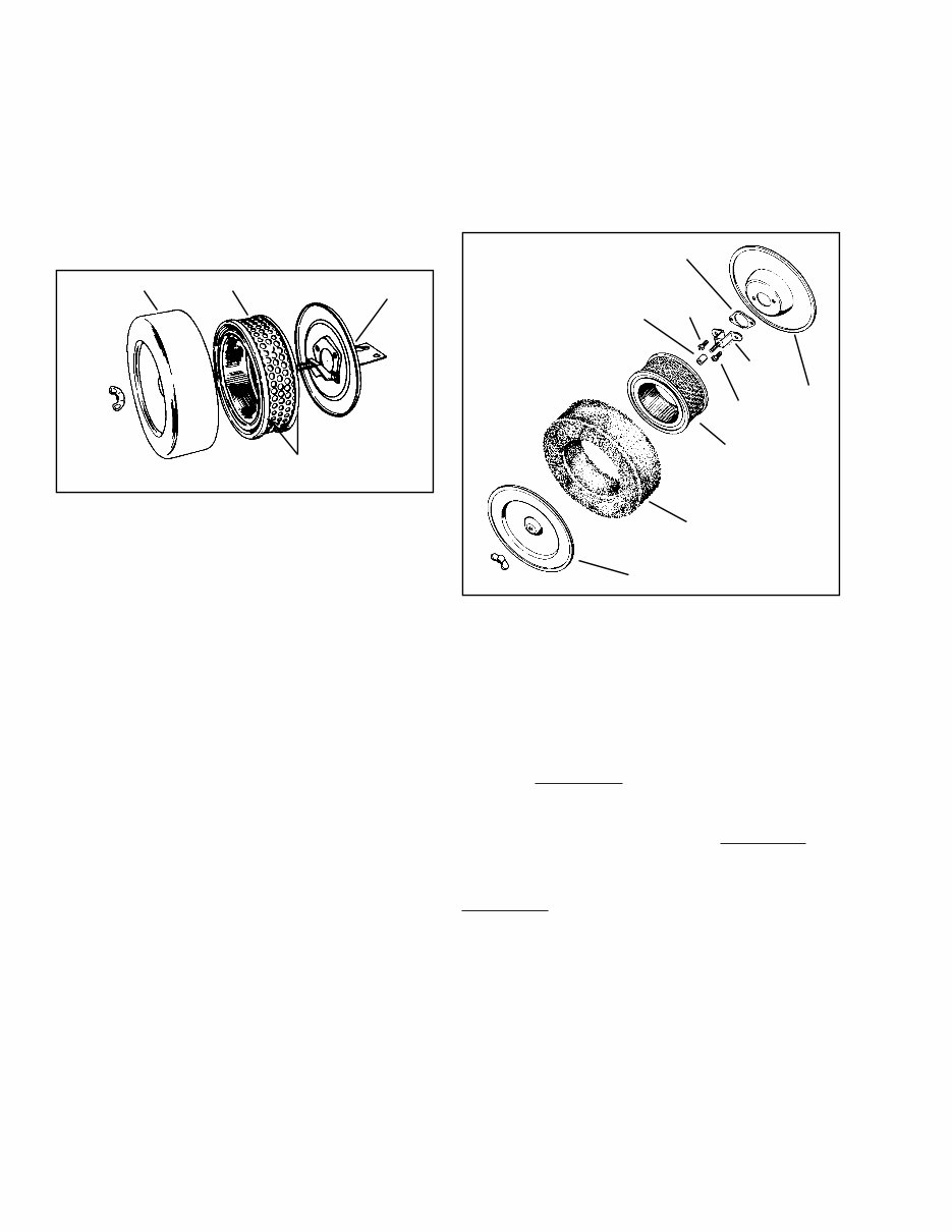
PAPER-TYPE AIR CLEANER SERVICE. Dry type
paper air cleaners are utilized on all Tecumseh Large
Frame engines. These air cleaners have treated paper
elements with rubberlike sealing edges. These edges
must seal properly to prevent dirt leakage.
PAPER-TYPE AIR CLEANER SERVICE. Replace
air filter once a year or more often in extremely dusty
or dirty conditions.
DO NOT ATTEMPT TO CLEAN OR OIL FILTER.
Be sure to clean base and cover thoroughly before
installing new paper filter.
NEVER RUN THE ENGINE WITHOUT THE COMPLETE
AIR CLEANER INSTALLED ON THE ENGINE.
NOTE: Serious damage to the engine may result in
using other than the specified part number filter.
Use factory recommended parts only.
POLYURETHANE-TYPE AIR CLEANER. Some
Tecumseh Large Frame engines may use a polyurethane
air filter in conjunction with a paper filter.
POLY-TYPE AIR CLEANER SERVICE. Clean and
re-oil every 3 months or every 25 operating hours,
whichever comes first. Clean daily if used in extremely
dusty or dirty conditions. Proceed as follows:
Remove wing nut and cover.
Slide foam filter off paper filter.
Wash foam filter in water and detergent solution and
squeeze, Don’t twist until all dirt is removed.
Rinse thoroughly in clear water.
Wrap in a clean cloth and squeeze, Don’t twist until
completely dry.
Saturate foam filter with engine oil and squeeze,
Don’t twist to distribute oil and remove excess oil.
Clean top side of base and inside of cover thoroughly.
Replace foam filter, cover and wing nut. Tighten wing
nut securely.
NEVER RUN ENGINE WITHOUT COMPLETE AIR
CLEANER INSTALLED ON ENGINE.
COVER ELEMENT
BASE
SEALING EDGES
GASKET
BOLT
SPACER
BRACKET
BOLT
BACK
COVER
PAPER
ELEMENT
POLY
OUTER ELEMENT
FRONT COVER
5
SECTION 2. GENERAL CARBURETOR INFORMATION
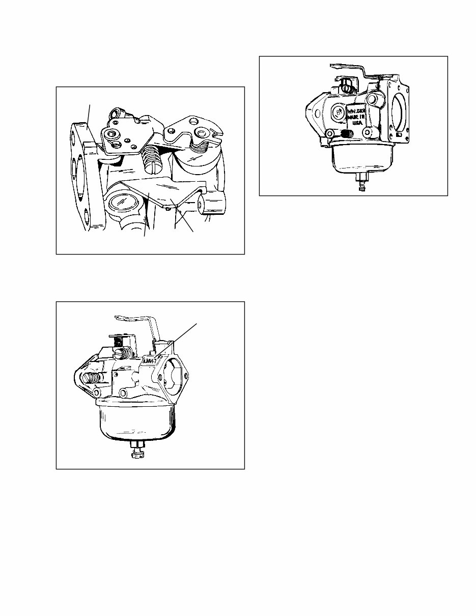
CARBURETOR IDENTIFICATION . Tecumseh
carburetors are identified by a model number and
code date stamping on the carburetor as illustrated.
When servicing carburetors, use the engine model
number or the model number on the carburetor and
proper section in the Master Parts Manual or Microfiche
Catalog for proper service information.
These carburetors are used on some HH80-100-
120 and VH80-100 engines.
This carburetor is used on the Overhead Valve engine
12, 14, 16 & 18 horsepower.
FLOAT-FEED CARBURETORS. Float-feed carburetors
use a hollow metal float to maintain the operating
level of fuel in the carburetor. As the fuel is used,
the fuel level in the carburetor bowl drops and the
float moves downward. This actuates the inlet needle
valve, to allow fuel to flow by gravity into the fuel
bowl. As the fuel level in the bowl again rises, it
raises the float. This float motion adjusts the fuel
flow at the proper rate and keeps the fuel at the
proper mixture level.
CARBURETOR
CODE DATE
CARBURETOR
MODEL NUMBER
ALTERNATE LOCATION
FOR MODEL NUMBER
89 3 F 5
89 3 F
CARBURETOR
MODEL NUMBER

6
SECTION 3. TECUMSEH CARBURETORS
Following are initial carburetor adjustments to be
used to start the engine. After the engine has reached
operating temperature make final adjustments.
Main Adjustment HH80-100-120
Screw VH100, 1-3/4 turns.
Idle Adjustment HH80-100-120
Screw VH100, 1-1/4 turns
The Master Parts Manual or Microfiche has a direct
engine-to carburetor reference list. Further identification
of the carburetor is stamped on the carburetor body
as shown. Refer to the standard service part number
and the identification number on the carburetor body,
in any correspondence.
CARBURETOR DISASSEMBLY, INSPECTION AND
ASSEMBLY. Carefully disassemble carburetor, removing
all non-metallic parts, i.e., gaskets, viton seats and
needles, “O” rings, fuel pump valve, etc.
THROTTLE. Examine the throttle lever shaft and
shutter prior to disassembly. Replace any worn parts.
1. Remove the screw in the center of the throttle
shutter and pull out the throttle shaft lever assembly.
2. When reassembling, replace the throttle shutter
with identifying marks as positioned prior to
disassembly. The throttle shaft must be held in
tight to the bottom bearing to prevent the throttle
shutter from riding on the throttle bore of the
body, causing excessive throttle shutter wear
and governor hunting.
CHOKE. Examine the choke lever, shaft and shutter
prior to disassembly. Replace any worn parts.
1. Remove the screw in the center of the choke
shutter and pull out the choke shaft lever assembly.
2. When reassembling, replace the choke shutter
with identifying marks as positioned prior to
disassembly. Hold the choke shaft securely into
the bearing bore when replacing the choke shutter.
IDLE ADJUSTMENT SCREW. Remove the idle screw
from the carburetor body and examine the point for
damage to the seating surface of the taper. Replace
any damaged parts.
CARBURETOR
MODEL NUMBER
WELCH PLUG
CHOKE LEVER
THROTTLE
LEVER
NOTE: IDENTIFYING MARK WILL BE
FOUND IN THE 3 O’CLOCK POSITION THROTTLE
SHUTTER
CHOKE SHUTTER CUT
OUT CLEARANCE FOR
INTERNAL VENT TUBE
GOOD BAD
7
HIGH SPEED ADJUSTMENT SCREW. For service,
examine the taper of the high speed adjustment screw.
If the taper is damaged at the area where it seats,
replace the screw and fuel bowl retainer nut as an
assembly.
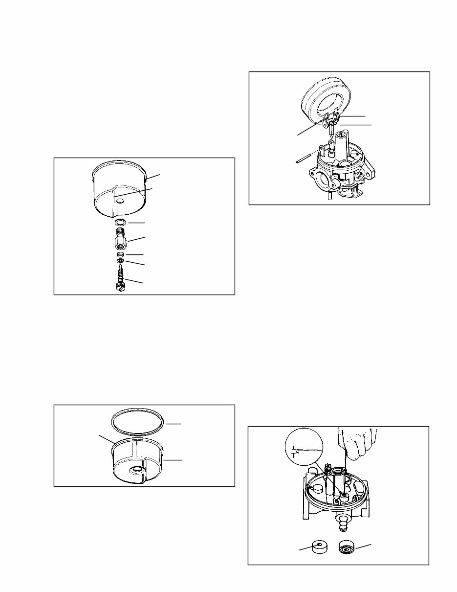
FUEL BOWL RETAINING NUT. Remove the fuel bowl
retaining nut including fiber washer.
Examine the small fuel passage in the annular groove
in the retaining nut. This passage must be clean
for the proper transfer of fuel into the idle metering
system. Replace any worn parts.
When replacing, torque the fuel bowl nut to 50-60
inch pounds.
INLET NEEDLE. The inlet needle is anchored to
the float tab by a clip, to assure proper movement
of the inlet needle off of the seat when the float
drops. The inlet needle clip must be positioned as
shown during reassembly.
FUEL BOWL. Check the bowl for corrosion or dirt.
Replace if necessary.
The fuel bowl must be free of dirt and corrosion.
When tearing down carburetor for repair, replace
fuel bowl “O” ring. Before installation lubricate the
“O” ring with a small amount of oil for easier installation.
The fuel bowl flat surface must be positioned on
the same side of the carburetor as the fuel inlet fitting
or same side as the float hinge pin to assure full
travel of the float.
FLOAT. Remove the float. Examine the float for crushing
or holes. Examine the float hinge bearing surfaces
through which the float hinge pin passes and replace
if worn.
Examine the inlet needle. If any wear is evident, or
any of the corners show signs of rounding, the needle
should be replaced.
The inlet needle hooks onto the float tab by means
of a spring clip. To prevent binding, the long, straight
end of the clip should face the choke end of the
carburetor as shown.
SERVICING THE VITON SEAT.
a. REMOVAL. If the seat is to be replaced use the
bent end of a paper clip or wire with a 3/32'’
(.24 mm) hook. Push the hook through the Viton
seat hole. Then with the hook, pull the Viton seat
out. Replace with a new seat.
NOTE: A #4 crochet hook can also be used for removal.
b. INSTALLATION.
NOTE: After thoroughly cleaning the cavity, moisten
the viton seat with oil.
Insert the seat with the grooved side into the
cup. Press the viton seat squarely into the base
with a punch.
FUEL BOWL
FLAT OF FUEL BOWL
TOWARD FUEL INLET
FITTING
FIBER WASHER
FUEL BOWL
RETAINING NUT
“O” RING
BRASS WASHER
HIGH SPEED ADJUSTMENT
SPRING AND SCREW
TORQUE TO
50 - 60 INCH
POUNDS
“O” RING
FUEL BOWL
CHECK FOR
CORROSION
AND DIRT
CLIP
LONG END
OF CLIP
OPEN END
OF CLIP
THROTTLE END
CHOKE END
3/32”
(.24 mm)
INLET NEEDLE
SEATS AT THIS
POINT
INSERT THIS
FACE FIRST
REMOVAL OF VITON SEAT
INSTALLATION OF VITON SEAT
HOOK END
8
HIGH SPEED NOZZLE. The carburetor body contains
a main nozzle emulsion tube pressed into the carburetor
body to a predetermined depth and positioned within
the venturi of the carburetor. Do not attempt to remove
this main nozzle. Repositioning of this nozzle will
seriously affect the metering characteristics of the
carburetor and will require replacement of the entire
carburetor.
FUEL INLET FITTING. If necessary, this fitting can
be removed by pulling and twisting. Be sure to install
the fitting in the same position as the original. When
installing the fitting, insert tip into the carburetor
body, then coat the exposed portion of the shank
with Loctite grade A; then press it in until the shoulder
contacts the carburetor body.
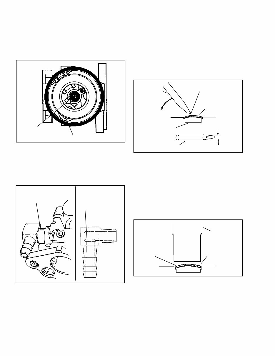
CARBURETOR BODY. When removing the choke
and throttle shafts, check shafts and bearings in
carburetor body for wear. Any looseness in these
areas can cause dirt to enter the engine and cause
premature wear. If dust seals are present, these should
be positioned next to the carburetor body.
To do a proper cleaning job, welch plugs should be
removed to expose drilled passages. To remove the
welch plug, sharpen a small chisel to a sharp wedge
point. Drive the chisel into the welch plug, push down
on chisel and pry plug out of position.
When all accessories and shafts have been removed,
soak the carburetor in carburetor cleaner for a maximum
of 30 minutes. Blow out all passages with compressed
air in the opposite direction of normal fuel flow or
use a soft tag wire. Clean all metallic parts with solvent.
To install a new welch plug after cleaning, place
the welch plug into receptacle with raised portion
up. With a punch equal, or greater than the size of
the plug, merely flatten the plug. Do not dent or drive
the center of the plug below the top surface of the
carburetor.
WELCH PLUG
MAIN NOZZLE
EMULSION TUBE
DO NOT REMOVE
PRESS IN PARTIALLY
THEN APPLY LOCTITE
GRADE A
SOME INLET FITTINGS
UTILIZED A STRAINER
SMALL CHISEL
PRY OUT PLUG
PIERCE PLUG WITH TIP
WELCH PLUG TO BE
REMOVED
DO NOT ALLOW
CHISEL POINT TO
STRIKE CARBURETOR
BODY
ABOUT 1/8” (3.2 MM)
WIDE
SMALL CHISEL
FLAT-END PUNCH
NEW WELCH
PLUG
SAME OR LARGER
DIAMETER OF PLUG
You're Reading a Preview
What's Included?
Fast Download Speeds
Online & Offline Access
Access PDF Contents & Bookmarks
Full Search Facility
Print one or all pages of your manual
$27.99
$36.99
Viewed 76 Times Today


Secure transaction
What's Included?
Fast Download Speeds
Online & Offline Access
Access PDF Contents & Bookmarks
Full Search Facility
Print one or all pages of your manual
$27.99
$36.99
Whether you're a professional mechanic or a DIY enthusiast, this 78-page Service/Technicians Manual for Tecumseh 8 to 18 hp Cast Iron 4-Cycle Engines is an invaluable resource. It covers models VH80, VH100, HH80, HH100, HH120, and OH120-180. This manual provides the technical information you need to troubleshoot and repair your Tecumseh engine.
Get your hands on this comprehensive manual to gain insights into maintaining and servicing your engine. It's a must-have for anyone looking to ensure their engine runs smoothly and efficiently.


