

TECUMSEH OVXL120 OVXL125 4 CYCLE OVERHEAD VALVE EngineS Full Service & Repair Manual
What's Included?
Fast Download Speeds
Online & Offline Access
Access PDF Contents & Bookmarks
Full Search Facility
Print one or all pages of your manual

This manual covers engine models:
OHH50 - 65, OHHSK50 - 130, OHV11 - OHV17, OVM120,
OVRM40-675, OVRM120, OVXL/C120, OVXL120, OVXL125.
Other illustrated Tecumseh 2-Cycle Engine, 4-Cycle Engine and
Transmission manuals; booklets; and wall charts are available
through Tecumseh.
For complete listing write or call
CONTAINS SEARS CRAFTSMAN CROSS REFERENCE
4-CYCLE
OVERHEAD
VALVE
ENGINES
T E C H N I C I A N ' S H A N D B O O K
TECUMSEH

i
CONTENTS
C Tecumseh Products Company
1998
Page
CHAPTER 1 GENERAL INFORMATION ....................... 1
ENGINE IDENTIFICATION ............................................. 1
INTERPRETATION OF MODEL NUMBER ..................... 1
SHORT BLOCKS ............................................................. 2
FUELS ............................................................................. 2
ENGINE OIL .................................................................... 2
CAPACITIES .................................................................... 2
OIL CHANGE INTERVALS .............................................. 3
OIL CHECK ...................................................................... 3
OIL CHANGE PROCEDURE .......................................... 3
TUNE-UP PROCEDURE ................................................. 3
STORAGE ....................................................................... 4
DRAINING THE FUEL SYSTEM ..................................... 4
OIL CYLINDER BORE .................................................... 4
CHAPTER 2 AIR CLEANERS ....................................... 5
GENERAL INFORMATION ............................................. 5
OPERATION .................................................................... 5
COMPONENTS ............................................................... 5
TROUBLESHOOTING OR TESTING ............................. 6
SERVICE ......................................................................... 6
DISASSEMBLY PROCEDURE ....................................... 6
POLYURETHANE-TYPE FILTER ELEMENT
OR PRE-CLEANER ..................................................... 7
PAPER -TYPE FILTER ELEMENT ................................. 7
FLOCKED SCREEN ........................................................ 7
CHAPTER 3 CARBURETORS AND FUEL SYSTEMS . 8
GENERAL INFORMATION ............................................. 8
OPERATION .................................................................... 8
FUEL PRIMERS .............................................................. 9
IMPULSE FUEL PUMPS ................................................. 9
FLOAT STYLE CARBURETORS .................................... 9
CARBURETOR VISUAL IDENTIFICATION .................... 10
SERIES I CARBURETORS ............................................. 10
SERIES III & SERIES IV CARBURETORS .................... 10
SERIES VI CARBURETORS .......................................... 10
SERIES VII ...................................................................... 10
SERIES VIII ..................................................................... 11
SERIES IX ....................................................................... 11
WALBRO MODEL LMK ................................................... 11
TESTING ......................................................................... 12
SERVICE ......................................................................... 12
CARBURETOR PRE-SETS AND ADJUSTMENTS ........ 12
PRE-SETS AND ADJUSTMENTS
(TECUMSEH AND WALBRO CARBURETORS) ......... 13
FINAL ADJUSTMENTS ................................................... 13
TECUMSEH CARBURETORS ........................................ 13
WALBRO CARBURETOR ............................................... 13
CARBURETOR DISASSEMBLY PROCEDURE ............. 14
IMPULSE FUEL PUMP ................................................... 15
FLOAT ADJUSTING PROCEDURE ................................ 16
INSPECTION ................................................................... 16
THROTTLE AND CHOKE ............................................... 16
IDLE AND HIGH SPEED MIXTURE ADJUSTING
SCREW ........................................................................ 16
FUEL BOWL RETAINING NUT ....................................... 16
FUEL BOWL, FLOAT, NEEDLE AND SEAT ................... 17
ASSEMBLY PROCEDURE ............................................. 18
WELCH PLUGS ............................................................... 18
THROTTLE SHAFT AND PLATE .................................... 18
CHOKE SHAFT AND PLATE .......................................... 19
FUEL INLET FITTING ..................................................... 19
HIGH AND LOW SPEED ADJUSTING SCREW,
MAIN NOZZLE ............................................................. 19
INLET NEEDLE AND SEAT ............................................ 20
FLOAT INSTALLATION ................................................... 20
FUEL BOWL AND BOWL NUT ....................................... 21
IMPULSE FUEL PUMP ................................................... 21
PRIMER BULB ................................................................ 21
FINAL CHECKS ............................................................... 21
CHAPTER 4 GOVERNORS AND LINKAGE ................. 22
GENERAL INFORMATION ............................................. 22
OPERATION .................................................................... 22
TROUBLESHOOTING .................................................... 22
ENGINE OVERSPEEDING ............................................. 22
ENGINE SURGING ......................................................... 22
SERVICE ......................................................................... 23
GOVERNOR ADJUSTMENT .......................................... 23
GOVERNOR GEAR AND SHAFT SERVICE .................. 23
GOVERNOR GEAR OR SHAFT REPLACEMENT,
UPSET STYLE GOVERNOR SHAFT .......................... 23
GOVERNOR SHAFT REPLACEMENT, RETAINING
RING STYLE ................................................................ 24
SPEED CONTROLS AND LINKAGE .............................. 25
CONVERSION TO REMOTE CONTROL ....................... 27
OVM, OVXL, OHV VERTICAL SPEED CONTROL ........ 28
OHV 11-17 HORIZONTAL SPEED CONTROL ............... 28
CHAPTER 5 RECOIL STARTERS ................................. 29
GENERAL INFORMATION ............................................. 29
OPERATION .................................................................... 29
COMPONENTS ............................................................... 29
SERVICE ......................................................................... 29
ROPE SERVICE .............................................................. 29
ROPE RETAINER REPLACEMENT ............................... 30
STYLIZED REWIND STARTER (OHH, OVRM, OHM,
OHSK, OVM, OVXL, OHV 11-13), AND STAMPED
STEEL STARTER ......................................................... 30
DISASSEMBLY PROCEDURE ....................................... 30
ASSEMBLY PROCEDURE ............................................. 31
STYLIZED REWIND STARTER WITH PLASTIC
RETAINER .................................................................... 31
DISASSEMBLY PROCEDURE ....................................... 31
ASSEMBLY ...................................................................... 32
KEEPER SPRING STYLE STARTERS .......................... 32
DISASSEMBLY PROCEDURE ....................................... 32
ASSEMBLY PROCEDURE ............................................. 33
STYLIZED STARTER (OHV 13.5 -17) ............................ 34
ASSEMBLY ...................................................................... 34
CHAPTER 6 ELECTRICAL SYSTEMS .......................... 35
GENERAL INFORMATION ............................................. 35
OPERATION .................................................................... 35
STARTING CIRCUIT AND ELECTRIC STARTERS ....... 35
CHARGING CIRCUIT ...................................................... 35
CONVERTING ALTERNATING CURRENT TO
DIRECT CURRENT ...................................................... 36
HALF WAVE RECTIFIER SINGLE DIODE ..................... 36
FULL WAVE RECTIFIER BRIDGE RECTIFIER ............. 36
COMPONENTS ............................................................... 36
BATTERY ......................................................................... 36
WIRING ............................................................................ 36
ELECTRICAL TERMS ..................................................... 37
BASIC CHECKS .............................................................. 37
TROUBLESHOOTING ELECTRICAL STARTER
CIRCUIT FLOW CHART .............................................. 38
TROUBLESHOOTING ELECTRICAL CHARGING
CIRCUIT FLOW CHART .............................................. 39
Page

ii
TESTING PROCEDURE ................................................. 40
STARTING CIRCUIT ....................................................... 40
CHARGING CIRCUIT ...................................................... 40
350 MILLIAMP CHARGING SYSTEM ............................ 40
18 WATT A.C. LIGHTING ALTERNATOR ....................... 41
35 WATT A.C. .................................................................. 41
2.5 AMP D.C., 35 WATT LIGHTING ............................... 41
3 AMP DC ALTERNATOR SYSTEM - DIODE IN
HARNESS SLEEVE ..................................................... 42
5 AMP D.C. ALTERNATOR SYSTEM
REGULATOR-RECTIFIER UNDER BLOWER
HOUSING ..................................................................... 43
3 AMP D.C. 5 AMP A.C. ALTERNATOR ......................... 43
MODELS OVM/OVXL/OHV12.5 ..................................... 44
MODELS OHV 13.5 - 17 (3/5 AMP SPLIT) ..................... 44
MODELS OVM/OVXL/OHV12.5
(RED BETWEEN ENGINE AND DIODE) .................... 44
MODELS OHV 13.5 - 17
(RED BETWEEN ENGINE AND DIODE) .................... 45
7 AMP D.C. ALTERNATOR SYSTEM
REGULATOR-RECTIFIER UNDER ENGINE
HOUSING ..................................................................... 45
10 AMP A.C. ALTERNATOR ........................................... 46
16 AMP ALTERNATOR SYSTEM WITH EXTERNAL
REGULATOR ................................................................ 46
VOLTAGE REGULATORS .............................................. 46
FUEL SHUT-DOWN SOLENOIDS .................................. 46
LOW OIL SHUTDOWN SWITCHES ............................... 47
LOW OIL PRESSURE SENSOR .................................... 47
LOW OIL SENSOR .......................................................... 47
ELECTRIC STARTER SERVICE .................................... 48
12 VOLT OR 120 VOLT ELECTRIC STARTERS ........... 48
INSPECTION AND REPAIR ............................................ 49
BRUSH CARD REPLACEMENT ..................................... 49
CHAPTER 7 FLYWHEEL BRAKE SYSTEMS ............... 50
GENERAL INFORMATION ............................................. 50
OPERATION .................................................................... 50
COMPONENTS ............................................................... 51
SERVICE ......................................................................... 51
BRAKE BRACKET ASSEMBLY ...................................... 52
IGNITION GROUNDOUT TERMINAL ............................. 52
STARTER INTERLOCK SWITCH ................................... 52
CONTROL CABLE .......................................................... 52
BRAKE BRACKET REPLACEMENT .............................. 52
CHAPTER 8 IGNITION ................................................... 53
GENERAL INFORMATION ............................................. 53
OPERATION .................................................................... 53
SOLID STATE IGNITION SYSTEM (CDI) ....................... 53
COMPONENTS ............................................................... 53
TESTING PROCEDURE ................................................. 54
FOUR CYCLE IGNITION TROUBLESHOOTING ........... 55
SERVICE ......................................................................... 56
SPARK PLUG SERVICE ................................................. 56
CONDITIONS CAUSING FREQUENT SPARK
PLUG FOULING ........................................................... 56
IGNITION TIMING CHECK ............................................. 57
SERVICE TIPS ................................................................ 57
Page
CHAPTER 9 INTERNAL ENGINE AND CYLINDER ..... 58
GENERAL INFORMATION ............................................. 58
OPERATION .................................................................... 58
4-CYCLE ENGINE THEORY .......................................... 58
LUBRICATION SYSTEMS .............................................. 59
COUNTERBALANCE SYSTEMS ................................... 59
COMPONENTS ............................................................... 60
ENGINE OPERATION PROBLEMS ............................... 61
ENGINE OPERATION PROBLEMS ............................... 62
TESTING ......................................................................... 63
ENGINE KNOCKS ........................................................... 63
ENGINE OVERHEATS .................................................... 63
SURGES OR RUNS UNEVENLY ................................... 63
ENGINE MISFIRES ......................................................... 63
ENGINE VIBRATES EXCESSIVELY .............................. 64
BREATHER PASSING OIL ............................................. 64
EXCESSIVE OIL CONSUMPTION ................................. 64
LACKS POWER .............................................................. 65
SERVICE ......................................................................... 65
DISASSEMBLY PROCEDURE ....................................... 65
CYLINDERS .................................................................... 68
CYLINDER HEAD AND VALVE TRAIN SERVICE ......... 69
VALVES, SPRINGS, AND PUSH RODS ........................ 69
PISTONS, RINGS, AND CONNECTING RODS ............. 70
PISTON ........................................................................... 70
PISTON RINGS ............................................................... 70
PISTON RING ORIENTATION ....................................... 70
CONNECTING RODS ..................................................... 71
CRANKSHAFTS AND CAMSHAFTS .............................. 71
CAMSHAFTS ................................................................... 71
VALVE SEATS ................................................................. 72
VALVE LIFTERS .............................................................. 73
VALVE GUIDES ............................................................... 73
VALVE GUIDE REMOVAL (OVM, OHM, OHSK110
& 120, OVXL ONLY) .................................................... 73
VALVE GUIDE INSTALLATION (OVM, OHM,
OHSK110 & 120, OVXL ONLY) ................................... 73
CRANKCASE BREATHERS ........................................... 74
TOP MOUNTED BREATHER ......................................... 74
SIDE MOUNTED BREATHER ........................................ 74
CYLINDER COVER, OIL SEAL, AND BEARING
SERVICE ...................................................................... 75
CYLINDER COVER ........................................................ 75
OIL SEAL SERVICE ........................................................ 75
CRANKSHAFT BEARING SERVICE .............................. 75
BALL BEARING SERVICE .............................................. 75
SERVICE BUSHING ....................................................... 76
BUSHING SIZE CHART .................................................. 76
ENGINE ASSEMBLY ...................................................... 76
CHAPTER 10 .................................................................. 83
ENGINE SPECIFICATIONS AND SEARS
CRAFTSMAN CROSS-REFERENCE ......................... 83
OVERHEAD VALVE SEARS CRAFTSMAN
CROSS REFERENCE ................................................. 83
ENGINE SPECIFICATIONS ............................................ 85
OVERHEAD VALVE TORQUE SPECIFICATIONS ........ 86
OVERHEAD VALVE TORQUE SPECIFICATIONS ........ 87
CHAPTER 11 EDUCATIONAL MATERIALS
AND TOOLS ............................................................... 88
Page
Copyright ' 1994 by Tecumseh Products Company
All rights reserved. No part of this book may be reproduced or transmitted, in any form or by any
means, electronic or mechanical, including photocopying, recording or by any information storage
and retrieval system, without permission in writing from Tecumseh Products Company Training
Department Manager.
1
CHAPTER 1 GENERAL INFORMATION
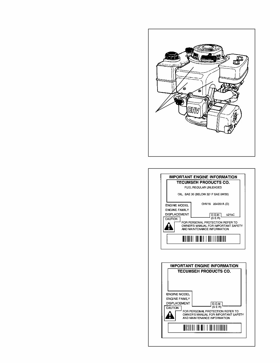
ENGINE IDENTIFICATION
Tecumseh engine model, specification, and serial
numbers or date of manufacture (D.O.M.) are stamped
into the blower housing, or located on a decal on the
engine in locations as illustrated (diag. 1 & 2). The
engine identification decal also provides the applicable
warranty code and oil recommendations (diag. 2).
Interpretation of Model Number
The letter designations in a model number indicate
the basic type of engine.
OHH - Overhead Valve Horizontal
OHM - Overhead Valve Horizontal
MediumFrame
OHSK - Overhead Valve Horizontal Snow King
OVM - Overhead Valve Vertical Medium Frame
OVRM - Overhead Valve Vertical Rotary Mower
OVXL - Overhead Valve Vertical Medium Frame
Extra Life
OHV - Overhead Valve Vertical
The number designations following the letters indicate
the basic engine model.
The number following the model number is the
specification number. The last three numbers of the
specification number indicate a variation to the basic
engine specification.
The serial number or D.O.M. indicates the production
date of the engine.
Using model OHV16-204207A, serial 5215C as an
example, interpretation is as follows:
OHV16-204207A is the model and specification
number.
OHV Overhead Valve Vertical
16 Indicates the basic engine model.
204207A is the specification number used for
properly identifying the parts of the
engine.
5215C is the serial number or D.O.M. (Date of
Manufacture)
5 is the last digit in the year of
manufacture (1995).
215 indicates the calendar day of that year
(215th day or August 3, 1995).
C represents the line and shift on which
the engine was built at the factory.
Emissionized engines that meet the California Air
Resource Board (C.A.R.B.) or the Environmental
Protection Agency (E.P.A.) standards will include
additional required engine information on the engine
decal.
NOTE: To maintain best possible emission
performance, use only Genuine Tecumseh Parts.
1
2
ENGINE MODEL
NUMBER
THIS ENGINE MEETS 1995-1998
CALIF. EMISSION REGULATIONS FOR
ULGE ENGINES AS APPLICABLE
FUEL: REGULAR UNLEADED OIL : USE SAE 30
OHV 125 203000A (D)
RTP358UIG2RA
358cc 3057D
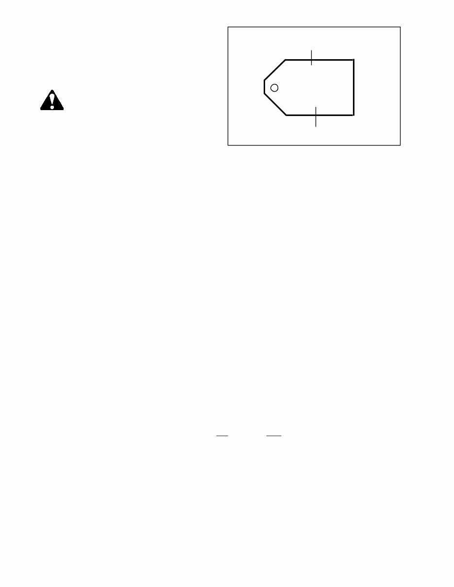
SHORT BLOCKS
New short blocks are identified by a tag marked S.B.H.
(Short Block Horizontal) or S.B.V. (Short Block
Vertical). Original model identification numbers of an
engine should always be transferred to a new short
block for correct parts identification (diag. 3).
THIS SYMBOL POINTS OUT IMPORTANT
SAFETY INSTRUCTIONS WHICH IF NOT
FOLLOWED COULD ENDANGER THE
PERSONAL SAFETY OF YOURSELF AND
OTHERS. FOLLOW ALL INSTRUCTIONS.
SBV OR SBH IDENTIFICATION NUMBER
3
FUELS
Tecumseh Products Company strongly recommends the use of fresh, clean, unleaded regular gasoline in all
Tecumseh Engines. Unleaded gasoline burns cleaner, extends engine life, and promotes good starting by
reducing the build up of combustion chamber deposits. Unleaded regular, unleaded premium or reformulated
gasoline containing no more than 10% Ethanol, or 15% MTBE, or 15% ETBE may also be used.
Leaded fuel is generally not available in the United States and should not be used if any of the above options
are available.
Never use gasoline, fuel conditioners, additives or stabilizers containing methanol, white gas, or fuel blends
which exceed the limits specified above for Ethanol, MTBE, or ETBE because engine/fuel system damage
could result.
Regardless of which of the approved fuels are used, fuel quality is critical to engine performance. Fuel should
not be stored in an engine or container more than 30 days prior to use. This time may be extended with the
use of a fuel stabilizer like TECUMSEH’S, part number 730245.
See "STORAGE" instructions in the Technician’s Manual, Operators Manual, or Bulletin 111.
ENGINE OIL
TECUMSEH FOUR CYCLE ENGINES REQUIRE THE USE OF A CLEAN, HIGH QUALITY DETERGENT
OIL. Be sure original container is marked: A.P.I. service "SF" thru "SJ" or "CD".
TECUMSEH RECOMMENDS USING ONE OF THE FOLLOWING FOUR CYCLE OILS THAT ARE SPECIALLY
FORMULATED TO TECUMSEH SPECIFICATIONS.
DO NOT USE SAE10W40 OIL.
FOR SUMMER (Above 32
0
F) (0
o
C) USE SAE30 OIL. PART #730225
Use SAE30 oil in high temperature, high load applications. Using multigrade oil may increase oil consumption.
FOR WINTER (Below 32
0
F) (0
o
C) USE SAE5W30 OIL. PART #730226
(SAE 10W is an acceptable substitute.)
(BELOW 0
0
F (-18
o
C) ONLY): SAE 0W30 is an acceptable substitute.
NOTE: For severe, prolonged winter operation of HH120 model, SAE10W oil is recommended.
Capacities
Engine Model Oz. ml.
OHH,OHSK 50-70 21 630
OVRM 40 - 6.75 21 630
OVRM105 & 120 21 630
OHSK80 - 100 26 720
OHM, OHSK 110* - 130 32 960
OVM 120, OVXL 120, 125 32 960
OHV 11 - 13 without oil filter 32 960
OHV 11 - 13 with filter 39 1170
OHV 13.5 - 17 without oil filter 55 1650
OHV 13.5 -17 2 1/4" filter (part # 36563) 62 1860
OHV 13.5 -17 2 5/8" filter (part # 36262) 64 1920
* NOTE: Model OHSK110 with a spec. of 221000 and up, have a capacity of 26 oz. (720 ml.)
2
SHORT BLOCK IDENTIFICATION TAG
SERIAL NUMBER
SBV- 564A
SER 5107
3
Oil Change Intervals: Change the oil after the first two (2) hours of operation and every 25 hours thereafter
(OHH & OHSK50-130, OHV13.5-17 every 50 hours), or more often if operated under dusty or dirty conditions.
If the engine is run less than 25 hours per year, change the oil at least once per year.
NOTE: The oil filter (if equipped) requires changing every 100 hours or more often if operated under dusty or
dirty conditions.
Oil Check: Check the oil each time the equipment is used or every five (5) hours of operation. Position the
equipment so the engine is level when checking the oil.
CAUTION: Remove the spark plug wire before doing any service work on the engine.
Oil Change Procedure: Locate the oil drain plug. On some units this plug is located below the deck
through the bottom of the mounting flange. Other units drain at the base of the engine above the deck or
frame. On some rotary mower applications, where access to the drain plug is restricted by the equipment, it
may be necessary to drain the oil by tipping the mower in a position that would allow the oil to drain out of the
fill tube.
On units that the drain plug is accessible, remove the plug and allow the oil to drain into a proper receptacle.
Always make sure that drain oil is disposed of properly. Contact your local governing authorities to find
a waste oil disposal site.
Once the oil is drained, reinstall the drain plug and fill the engine with new oil to the proper capacity.
TUNE-UP PROCEDURE:
NOTE: Today’s fuels can cause many problems in an engines performance due to the fuels quality and short
shelf life. Always check fuel as a primary cause of poor engine performance.
The following is a minor tune-up procedure. When this procedure is completed, the engine should operate
governor springs or linkage. Make the proper governor adjustments and carburetor presets where
required.
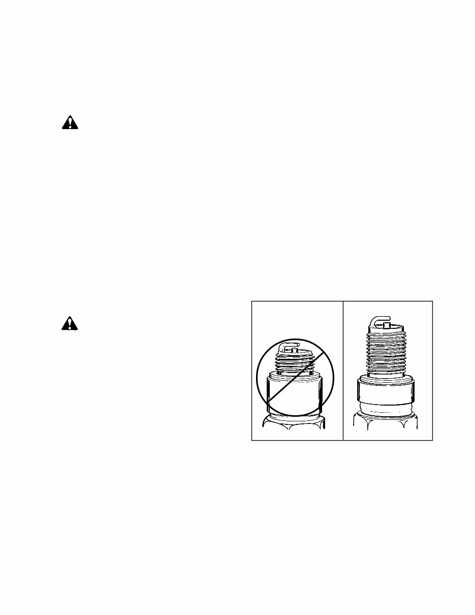
5. When replacing the spark plug, consult the proper parts breakdown for the spark plug to be used
in the engine being serviced. Set the proper spark plug gap (.030") (.762 mm) and install the spark
plug in the engine. Tighten the spark plug to 21 foot pounds (28 Nm) of torque. If a torque wrench
isnt available, screw the spark plug in as far as possible by hand, and use a spark plug wrench
to turn the spark plug 1/8 to 1/4 turn further if using the old spark plug, or 1/2 turn further if using
a new spark plug.
6. Make sure all ignition wires are free of abrasions or breaks and are properly routed so they will not rub
on the flywheel.
7. Properly reinstall the blower housing, gas tank, fuel line, and air cleaner assembly if removed.
8. Make sure all remote cables are properly adjusted for proper operation. See Chapter 4 under "Speed
Controls and Linkage".
9. Reinstall the spark plug wire, add fuel and oil as necessary, start the engine.
properly. Further repairs may be necessary if the
engine’s performance remains poor.
CAUTION: Remove the spark plug wire
before doing any service work on the engine.
1. Service or replace the air cleaner. See
Chapter 2 under "Service".
2. Inspect the level and condition of the oil and
change or add oil as required.
3. Remove the blower housing and clean all dirt,
grass or debris from the intake screen, head,
cylinder cooling fins, carburetor, governor
levers and linkage.
4. Make sure the fuel tank, fuel filter and fuel
line are clean. Replace any worn or damaged
4
OHV STANDARD
PLUG

4
STORAGE (IF THE ENGINE IS TO BE UNUSED FOR 30 DAYS OR MORE)
CAUTION: NEVER STORE THE ENGINE WITH FUEL IN THE TANK INDOORS OR IN ENCLOSED,
POORLY VENTILATED AREAS, WHERE FUEL FUMES MAY REACH AN OPEN FLAME, SPARK
OR PILOT LIGHT AS ON A FURNACE, WATER HEATER, CLOTHES DRYER OR OTHER GAS
APPLIANCE.
Gasoline can become stale in less than 30 days and form deposits that can impede proper fuel flow and
engine operation. To prevent deposits from forming, all gasoline must be removed from the fuel tank and
the carburetor. An acceptable alternative to removing all gasoline, is by adding Tecumseh’s fuel stabilizer,
part number 730245, to the gasoline. Fuel stabilizer is added to the fuel tank or storage container. Always
follow the mix ratio found on the stabilizer container. Run the engine at least 10 minutes after adding
the stabilizer to allow it to reach the carburetor.
Draining the Fuel System
CAUTION: DRAIN THE FUEL INTO AN APPROVED CONTAINER OUTDOORS, AND AWAY FROM
ANY OPEN FLAME OR COMBUSTION SOURCE. BE SURE THE ENGINE IS COOL.
1. Remove all gasoline from the fuel tank by running the engine until the engine stops, or by draining the
fuel tank by removing the fuel line at the carburetor or fuel tank. Be careful not to damage the fuel line,
fittings, or fuel tank.
2. Drain the carburetor by pressing upward on bowl drain (if equipped) which is located on the bottom
of the carburetor bowl. On carburetors without a bowl drain, the carburetor may be drained by loosening
the bowl nut on the bottom carburetor one full turn. Allow to completely drain and retighten the bowl
nut being careful not to damage the bowl gasket when tightening.
3. If "Gasohol" has been used, complete the above procedure and then put one half pint of unleaded
gasoline into the fuel tank and repeat the above procedure. If Gasohol is allowed to remain in the fuel
system during storage, the alcohol content can cause rubber gaskets and seals to deteriorate.
Change Oil: If the oil has not been changed recently, this is a good time to do it. See "Oil Change Procedure"
on page 3.
Oil Cylinder Bore
1. Disconnect the spark plug wire and ground the spark plug wire to the engine. Remove the spark plug
and put a 1/2 ounce (15 ml.) of clean engine oil into spark plug hole.
2. Cover the spark plug hole with a shop towel.
3. Crank the engine over, slowly, several times.
4. Install the spark plug and connect the spark plug wire.
Clean Engine: Remove the blower housing and clean all dirt, grass or debris from the intake screen, head,
cylinder cooling fins, carburetor, governor levers and linkage.
5
CHAPTER 2 AIR CLEANERS
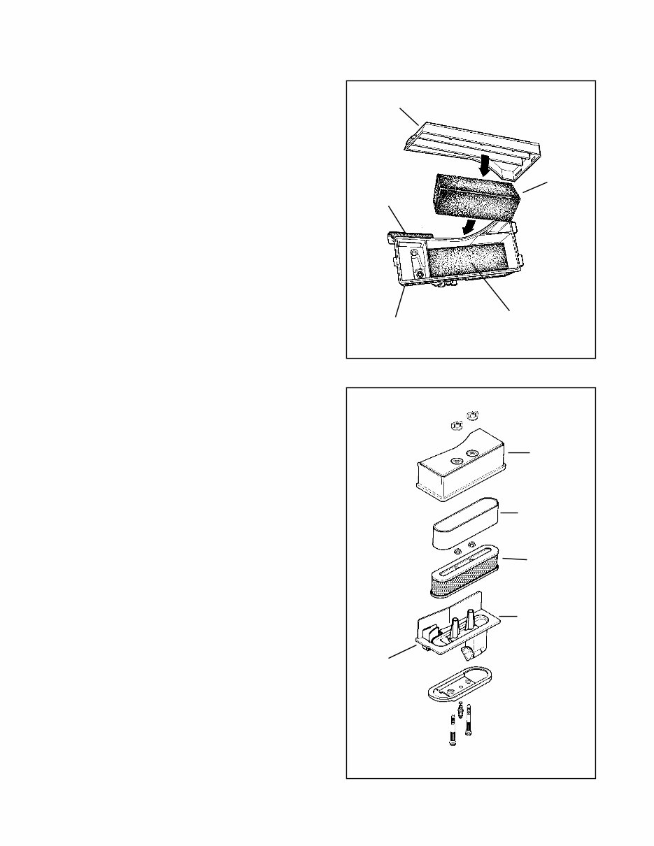
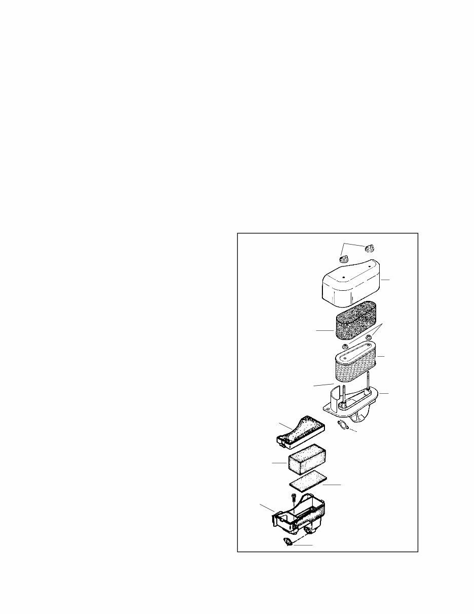
COMPONENTS
The cover holds the filter element and prevents large
debris from entering the filter body.
The polyurethane wrap pre-cleaner is used on XL
or XL/C engine models with paper filter elements.
The paper or polyurethane filter element is the main
filter to trap dust and dirt. Dry-type paper elements
are pleated paper for increased surface area and
rubberized sealing edges. The polyurethane filter uses
an oil film to trap fine particles found in dust.
The flocked screen is used as an additional filter on
XL or XL/C engine models that use a polyurethane
filter element.
2
KLEEN-AIRE
fi
ENTRANCE FROM
UNDER BLOWER
HOUSING
COVER
POLYURETHENE
WRAP
PAPER
ELEMENT
AIR CLEANER
BODY
FOAM
ELEMENT
FLOCKED SCREEN
AIR CLEANER
BODY
KLEEN-AIRE
fi
ENTRANCE FROM
UNDER BLOWER
HOUSING
COVER
1
GENERAL INFORMATION
The air cleaner is the device used to eliminate dust
and dirt from the air supply. Filtered air is necessary
to assure that abrasive particles are removed before
entering the combustion chamber. Dirt allowed into
the engine will quickly wear the internal components
and shorten the life of the engine.
Tecumseh engines use either a polyurethane or a
paper-type air filter system. A polyurethane pre-
cleaner or a flocked screen may be used with the main
filter. Snow King
fi
engines do not use an air filter due
to the clean operating environment and to prevent filter
freeze-up.
Extremely dirty conditions may require more frequent
filter cleaning or replacement.
OPERATION
The air cleaner cover allows access to the air filter
element(s) and prevents large particles from entering
the filter body. Air is filtered through the pre-cleaner
or flocked screen if equipped, and the polyurethane
or paper filter element. Pre-cleaners or flocked
screens provide more air cleaning capacity.
In Tecumseh’s Kleen Aire
fi
system, air is drawn in
through a rotating screen or recoil housing to be
centrifugally cleaned by the flywheel before the air
enters the air filter.
6
DISASSEMBLY PROCEDURE
1. Unlock the tabs or remove the screws or wing
nuts holding the air cleaner cover in place.
2. Remove the hex nuts holding the element
down if equipped. New nuts are supplied with
a new filter and are to be used for proper
sealing.
3. Clean the excess contaminants out of the air
cleaner body before removing the old
element.
4. Remove the old element and the polyurethane
pre-cleaner if equipped.
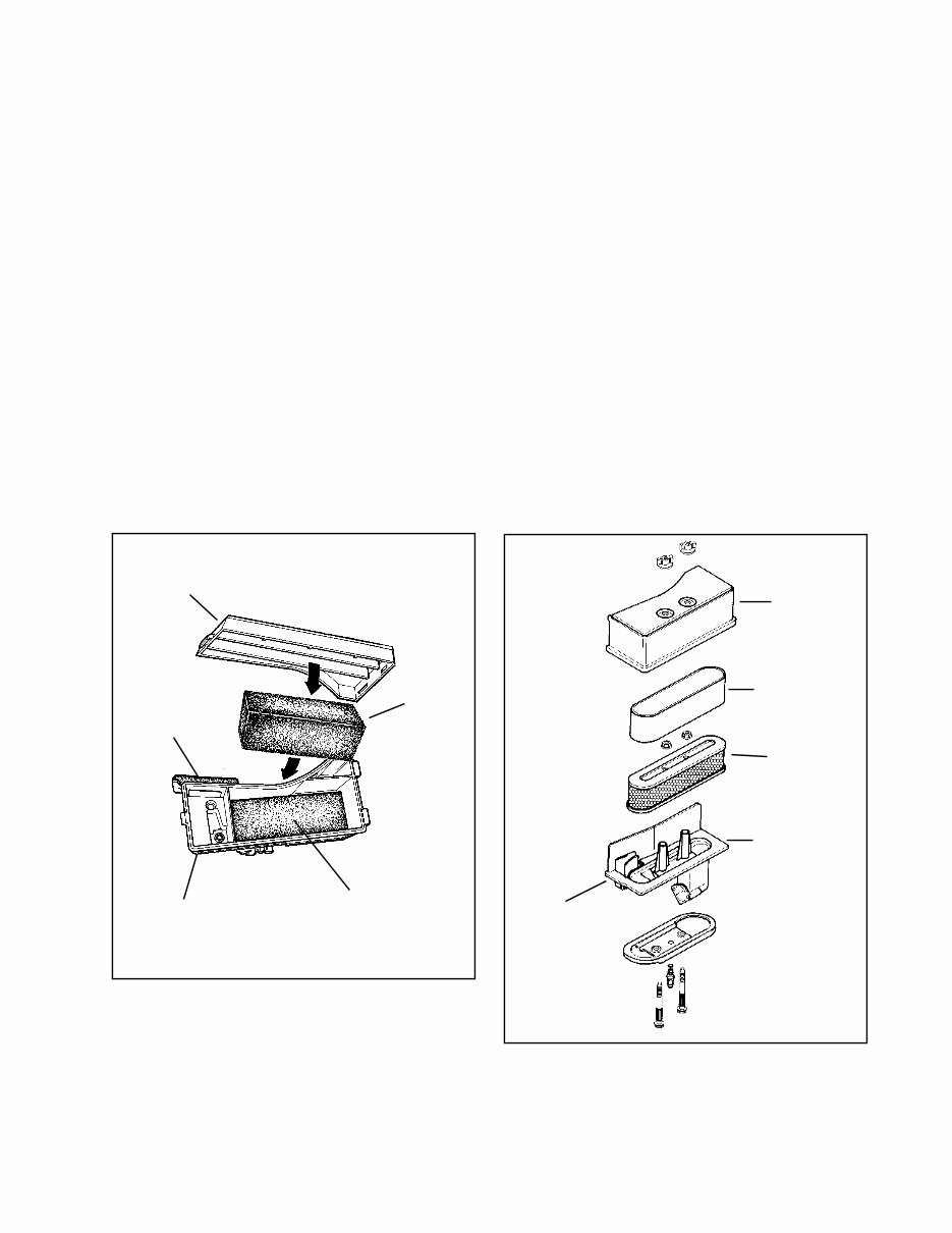
5. On air cleaners that use a flocked screen
under the polyurethane element, remove the
air cleaner assembly from the carburetor
before removing the flocked screen. This
prevents dirt from entering the carburetor
(diag 3).
6. Clean the inside of the cover and body,
remove the old gasket between the carburetor
and the air cleaner assembly.
7. Reinstall the air cleaner assembly using a new
gasket.
8. Use reverse procedure for reassembly. When
installing the polyurethane pre-cleaner, make
sure the seam is installed to the outside to
prevent gaps between the paper element and
the pre-cleaner.
TROUBLESHOOTING OR TESTING
If the engine’s performance is unsatisfactory (needs excessive carburetor adjustments, starts smoking
abnormally, loses power), the first engine component to be checked is the air filter. A dirt restricted or an oil
soaked filter will cause noticeable performance problems. A polyurethane filter may be cleaned following the
service procedure listed under "Service" in this chapter. A paper-type air filter should only be replaced. A
paper-type filter cannot have an oil film present on the paper. Follow the procedure listed in the "Service"
section of this chapter for filter replacement or cleaning.
SERVICE
Service on the polyurethane filter element (cleaning and oiling) is recommended every three (3) months or
every twenty five (25) operating hours, whichever comes first. Extremely dirty or dusty conditions may require
daily cleanings.
The paper filter element should be replaced once a year or every 100 operating hours, more often if used in
extremely dusty conditions.
NOTE: NEVER RUN THE ENGINE WITHOUT THE COMPLETE AIR CLEANER ASSEMBLY INSTALLED ON
THE ENGINE. ALWAYS REPLACE THE FILTER ELEMENT WITH THE PROPER TECUMSEH ORIGINAL
REPLACEMENT PART.
WING NUTS
COVER
FILTER A
(FOAM)
FILTER B
COVER
FOAM
FILTER
FLOCKED SCREEN
GASKET
KLEEN-AIRE
fi
ENTRANCE
GASKET
NUTS
BODY
GASKET
3
KLEEN-AIRE
fi
ENTRANCE
7
Polyurethane-Type Filter Element or pre-cleaner
This type of air filter or pre-cleaner can be serviced when restricted with dust or dirt. Wash the filter or pre-
cleaner in a detergent and water solution until all the dirt is removed. Rinse in clear water to remove the
detergent solution. Squeeze the filter or pre-cleaner (do not twist) to remove the excess water. Wrap the filter
or pre-cleaner in a clean cloth and squeeze it (do not twist) until completely dry.
On the polyurethane filter only, re-oil the filter by applying engine oil and squeezing it vigorously to distribute
the oil. Roll the filter in a cloth and squeeze it (do not twist) to remove the excess oil. The pre-cleaner must not
be oiled.
Clean the air cleaner housing and cover being careful not to allow dirt to fall into the carburetor or intake pipe.
Paper -type filter element
Paper type air filter elements can only be serviced by replacement. Do not attempt to clean a paper filter
element. Replacement filters are available at any authorized Tecumseh Service Outlet. Be sure to use new
filter nuts or seals for the air cleaner studs if supplied with the new filter (diag. 5).
Flocked Screen
A flocked screen may be cleaned by blowing compressed air through the screen from the backside. If the
screen cannot be cleaned with this procedure, it should be replaced with a new screen.
FOAM
ELEMENT
FLOCKED SCREEN
AIR CLEANER
BODY
KLEEN-AIRE
fi
ENTRANCE FROM
UNDER BLOWER
HOUSING
COVER
4
KLEEN-AIRE
fi
ENTRANCE FROM
UNDER BLOWER
HOUSING
COVER
POLYURETHENE
WRAP
PAPER
ELEMENT
AIR CLEANER
BODY
5
You're Reading a Preview
What's Included?
Fast Download Speeds
Online & Offline Access
Access PDF Contents & Bookmarks
Full Search Facility
Print one or all pages of your manual
$31.99
Viewed 36 Times Today


Secure transaction
What's Included?
Fast Download Speeds
Online & Offline Access
Access PDF Contents & Bookmarks
Full Search Facility
Print one or all pages of your manual
$31.99
Get instant access to the Complete Factory Service Repair Workshop Manual without any extra fees or expiry dates. This Professional Manual is suitable for both professional Mechanics and Technicians, as well as DIY enthusiasts. It covers all repairs, servicing, and troubleshooting procedures with highly detailed photos, diagrams, and step-by-step instructions. You can print out a single page or the entire manual as per your preference. The manual can be used on multiple computers without any limitations or trial periods, and it does not expire or require any renewal fees. It is fully compatible with Windows and MAC computers.
- Comprehensive coverage of repairs, servicing, and troubleshooting procedures
- Highly detailed photos, diagrams, and exploded views
- Step-by-step instructions for completing every job correctly
- Printable pages without any restrictions
- Multi-computer usage without limitations
- No expiry dates or renewal fees
- Full compatibility with Windows & MAC computers
Click the button to access this invaluable resource for all your car repair needs.


