

Subaru Engine EX35 and EX40 Technician / Service Manual
What's Included?
Fast Download Speeds
Online & Offline Access
Access PDF Contents & Bookmarks
Full Search Facility
Print one or all pages of your manual

1. SPECIFICATIONS . . . . . . . . . . . . . . . . . . . . . . . . . . . . . . . . . . . . . . . . . . . . . . . 1
2. PERFORMANCE . . . . . . . . . . . . . . . . . . . . . . . . . . . . . . . . . . . . . . . . . . . . . . . 2
3. FEATURES (EX35, 40 series) . . . . . . . . . . . . . . . . . . . . . . . . . . . . . . . . . . . . . 5
4. GENERAL DESCRIPTION OF ENGINE COMPONENTS . . . . . . . . . . . . . . . . 6
5. DISASSEMBLY AND REASSEMBLY . . . . . . . . . . . . . . . . . . . . . . . . . . . . . . . 12
5-1 PREPARATIONS AND PRECAUTIONS . . . . . . . . . . . . . . . . . . . . . . . . . . . 12
5-2 SPECIAL TOOLS . . . . . . . . . . . . . . . . . . . . . . . . . . . . . . . . . . . . . . . . . . . . . 12
5-3 DISASSEMBLY PROCEDURE . . . . . . . . . . . . . . . . . . . . . . . . . . . . . . . . . . 13
5-4 REASSEMBLY PROCEDURE . . . . . . . . . . . . . . . . . . . . . . . . . . . . . . . . . . . 27
6. ENGINE OIL . . . . . . . . . . . . . . . . . . . . . . . . . . . . . . . . . . . . . . . . . . . . . . . . . . . 45
7. MAGNETO . . . . . . . . . . . . . . . . . . . . . . . . . . . . . . . . . . . . . . . . . . . . . . . . . . . . 46
8. IGNITION SYSTEM . . . . . . . . . . . . . . . . . . . . . . . . . . . . . . . . . . . . . . . . . . . . . . 47
9. WIRING DIAGRAM . . . . . . . . . . . . . . . . . . . . . . . . . . . . . . . . . . . . . . . . . . . . . . 48
10. ELECTRIC STARTER . . . . . . . . . . . . . . . . . . . . . . . . . . . . . . . . . . . . . . . . . . . 50
11. OIL SENSOR . . . . . . . . . . . . . . . . . . . . . . . . . . . . . . . . . . . . . . . . . . . . . . . . . . 52
12. AUTOMATIC DECOMPRESSION SYSTEM . . . . . . . . . . . . . . . . . . . . . . . . . . 53
13. CARBURETOR . . . . . . . . . . . . . . . . . . . . . . . . . . . . . . . . . . . . . . . . . . . . . . . . 54
14. RECOIL STARTER . . . . . . . . . . . . . . . . . . . . . . . . . . . . . . . . . . . . . . . . . . . . . 58
15. INSTALLATION . . . . . . . . . . . . . . . . . . . . . . . . . . . . . . . . . . . . . . . . . . . . . . . . 63
16.TROUBLESHOOTING . . . . . . . . . . . . . . . . . . . . . . . . . . . . . . . . . . . . . . . . . . . 66
17. STANDARD REPAIR TABLES . . . . . . . . . . . . . . . . . . . . . . . . . . . . . . . . . . . . 72
17-1 STANDARD DIMENSIONS AND LIMITS OF USE . . . . . . . . . . . . . . . . . . 72
17-2 SERVICE DATA (The following are only for your reference.) . . . . . . . . . . . 77
17-3 TIGHTENING TORQUE. . . . . . . . . . . . . . . . . . . . . . . . . . . . . . . . . . . . . . . 78
17-4 AIR GAP AND CLEARANCE . . . . . . . . . . . . . . . . . . . . . . . . . . . . . . . . . . . 78
18.MAINTENANCE AND STORAGE . . . . . . . . . . . . . . . . . . . . . . . . . . . . . . . . . . 79
CONTENTS
Section Title Page

- 1 -
1. SPECIFICATIONS
*Specifications are subject to change without notice.
Model EX35D EX40D
Type
Air-Cooled, 4-Cycle, Slant Single-Cylinder,
Horizontal P.T.O. Shaft, OHC Gasoline Engine
Bore & Stroke mm (in.) 89 × 65 (3.50 × 2.56)
Piston Displacement ml (cu.in.) 404 (24.65)
Compression Ratio 8.3
Continuous Output kW(HP)/r.p.m.
5.5(7.5)/3000
6.3(8.5)/3600
6.3(8.5)/3000
7.0(9.5)/3600
Maximum Output kW(HP)/r.p.m. 7.4(10.0)/3600 8.8(12.0)/3600
Maximum Torque
N ・ m / r.p.m.
(kgf ・ m / r.p.m.)
(ft ・ lb. / r.p.m.)
26/2400
(2.6/2400)
(19.18/2400)
27/2400
(2.7/2400)
(19.91/2400)
Direction of Rotation Counterclockwise as viewed from the P.T.O. shaft side
Valve Arrangement Overhead cam system
Cooling System Forced air cooling system
Lubrication System Splash lubrication system
Lubricant
Automobile engine oil ; Grade SE or higher (SG,SH or SJ in recomended)
SAE 10W-30-----Under ordinary atmospheric temperatures
SAE 5W-30-------In cold areas
Capacity of Lubricant L 1.2
Carburetor Horizontal draft, Float type
Fuel Automobile unleaded gasoline
Fuel Consumption Rate g/kW ・ h (g/HP ・ h) 381 (280)
Fuel Supply System Gravity type
Fuel Tank Capacity L 7.0
Ignition System Transistorized magneto
Spark Plug NGK BR-6HS
Charging Capacity (Option) V-A 12-1A, 3A, 16.7A (Option)
Starting System Recoil starter / Electric starter (Option)
Governor System Centrifugal flyweight system
Dry Weight kg (lb.) 33 (72.75)
Dimensions (L x W x H) mm (in.) 389 x 450 x 443 (15.31 x 17.72 x 17.44)

- 2 -
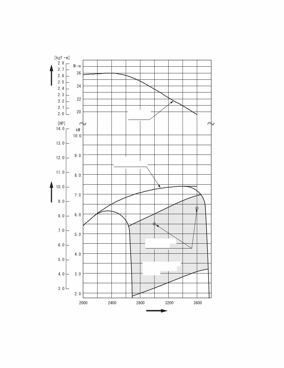
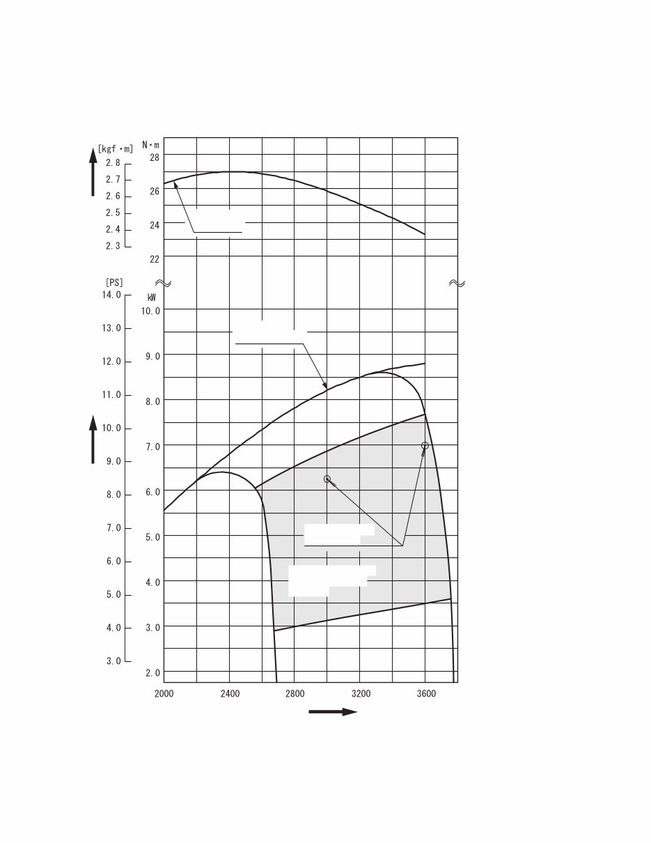
2. PERFORMANCE
2-1 MAXIMUM OUTPUT
The Maximum output is the output of an engine with its throttle valve fully opened and considering that all the
moving parts are properly broken in.
A new engine may not produce full maximum output while its moving parts are still not broken-in.
NOTE :
Power curves shown in the following charts are made in conformity with SAE internal combustion engine
standard test code J1349.
2-2 CONTINUOUS RATED OUTPUT
The continuous rated output is the output of an engine at optimum governed speed which is most favorable
from the view point of engin’s life and fuel consumption.
When the engine is installed on a certain equipment, it is recommended that the continuous output required
from the equipment to be kept below this continuous rated output.
2-3 MAXIMUM TORQUE
The maximum torque is the torque at the output shaft when the engine is producing maximum output at a
specific r.p.m..
- 3 -
EX35D
MAXIMUM
TORQUE
MAXIMUM
HORSEPOWER
r.p.m. REVOLUTION
TORQUE
OUTPUT
CONTINUOUS
RATED HP
RECOMMENDED
HORSEPOWER
RANGE
2-4 PERFORMANCE CURVES
- 4 -
EX40D
MAXIMUM
TORQUE
MAXIMUM
HORSEPOWER
r.p.m. REVOLUTION
TORQUE
OUTPUT
CONTINUOUS
RATED HP
RECOMMENDED
HORSEPOWER
RANGE

- 5 -
3. FEATURES (EX35, 40 series)
3-1 HIGH OUTPUT
Thanks to the adoption of a cam profile exclusively for intake and exhaust and the optimization of the shape
of the intake/exhaust port and the shape of the combustion chamber, the top-of-the-class-level maximum
output is achieved.
3-2 EXTREMELY SILENT - SOFT TONE QUALITY
EX engines are 2dBA quieter and softer in tone than other engines in the same class.
This quiet and soft tone is achieved by:
- Resin blower housing reduce noise leakage of mechanical noise.
- Employment of an optimized capacity Rigid Muffler.
3-3 EXTREMELY EASY START
Reliable Starting and Less Pulling Force are achieved by:
Sophisticated Mechanical Compression Release System as well as newly designed Combustion Chamber.
3-4 EXTREMELY EASY MAINTENANCE
Extreme ease of maintenance is realized by:
- High Parts Commonality
simplifies maintenance & lowers repair cost due to fewer parts for service.
- Only with ordinary tools, routine maintenance, assembly and disassembly can be performed.
3-5 EXTREMELY ADVANCED TECHNOLOGY
Extreme reliability and durability are achieved by:
- Heavy Duty Chain Driven OHC System
Oval type case-hardened steel links enhance performance and resist stretching, which result in extended
maintenance free operation.
- Completely New Main Bearing Cover’s Design
Flush-mounted main bearing cover with lower moment of deformation significantly increases reliability and
engine life.
- Superior Cooling and Lubrication System
Heat reduction is achieved by more efficient, larger and more numerous cooling fins on crankcase, cylinder
and mounting base, as well as by outstanding oil delivery system.
- Large Ball Bearings on both ends of crankshaft for maximum stability under demanding loads.
- Cast Iron Cylinder Liner resists wear
3-6 EXTREME POWER AND PERFORMANCE
Extremely Higher Power and Lower Fuel Consumption are realized by:
- High speed and homogeneous combustion achieved by sophisticated Pentroof Combustion Chamber which
includes Intake and Exhaust Valves located at optimum angle.
- Straight Intake Port with minimal air flow resistance.
Environmentally friendly
EX engines comply with EPA Phase 2 and CARB Tier III Emission Regulations in the USA.
Extreme application compatibility
With four versatile models, existing slant-cylinder engines can be easily replaced.
- 6 -
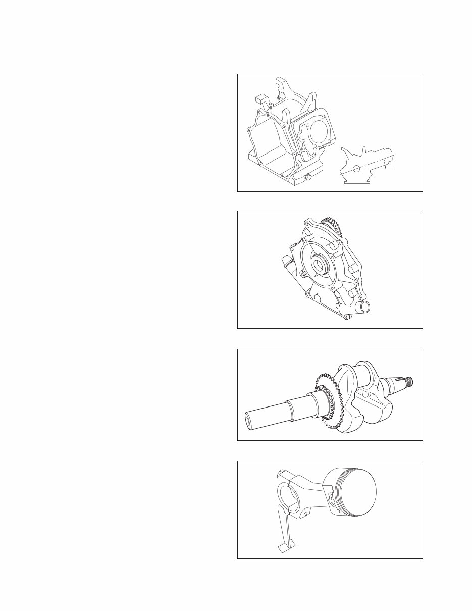
4. GENERAL DESCRIPTION OF ENGINE COMPONENTS
4-1 CYLINDER AND CRANKCASE
The cylinder and crankcase are aluminum die-casting
as a single piece. A special cast iron cylinder liner is
molded into the aluminum die-casting.
The crankcase has a mounting surface on the output
shaft side to which the main bearing cover is attached.
The cylinder is inclined to the right at an angle of 25
degrees from the horizontal as viewed from the output
shaft side.
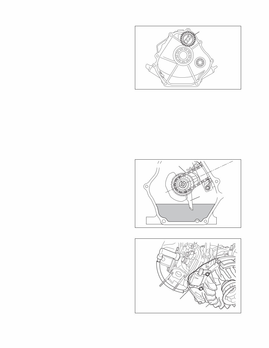
4-2 MAIN BEARING COVER
The main bearing cover is an aluminum die-casting,
which is mounted on the output shaft side of the
crankcase. By removing the main bearing cover, the
inside of the engine can be inspected with ease.
Pilots and bosses are machined into the cover
to facilitate the direct coupling of the engine with
machines such as generators and pumps.
Oil gauges (fillers) are on both sides of the cover for
easy maintenance.
4-3 CRANKSHAFT
The crankshaft is forged carbon steel, and the crank
pin is high-frequency inductionhardened.
The crank sprocket used to drive the chain and the
gear used to drive the governor gear are pressed into
the output end of the shaft.
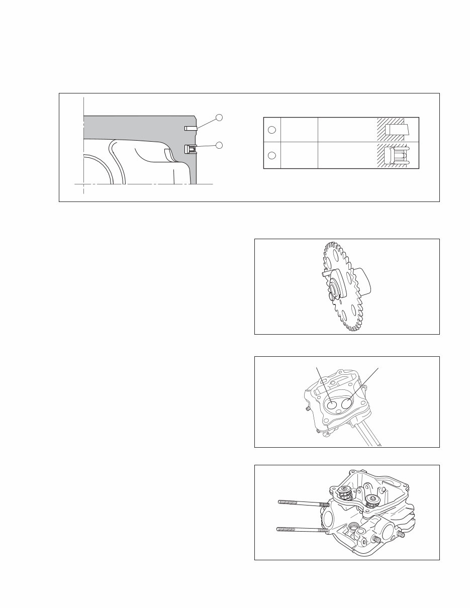
4-4 CONNECTING ROD AND PISTON
The connecting rod is a specially heat-treated
aluminum alloy die-casting. Its large and small ends
function as bearings. A splasher built into the
connecting rod lubricates by splashing engine oil.
The piston is an aluminum alloy casting with grooves
for mounting one compression ring and one oil ring.
Fig.4-1
Fig.4-2
Fig.4-3
25°
Fig.4-4
- 7 -
Fig.4-6
Fig.4-5
4-7 VALVE ARRANGEMENT
This engine has a chain-driven overhead cam and
overhead valve construction, with a single cam which
has individual profile for intake and exhaust to
perform high output.
Fig.4-7
EXHAUST VALVE
INTAKE VALVE
Fig.4-8
4-8 CYLINDER HEAD
The cylinder head is on aluminum die-casting with a
dome-shaped combustion chamber. The intake and
exhaust ports are arranged in a cross direction to
improve combustion efficiency.
TOP
RING
OIL
RING
1
2
TAPER
THREE-PIECE
CONSTRUCTION
1
2
4-6 CAMSHAFT
The camshaft and the sprocket are made of special
sintered alloy. They are constructed as a single
piece. The camshaft is provided with intake and
exhaust cam, and the decompression release lever is
mounted on the sprocket shaft end side.
4-5 PISTON RINGS
The piston rings are made of special cast iron. The profile of the top ring is a tapered face.
The oil ring is designed for better sealing and less oil consumption, in combination with 3 pieces.
- 8 -
4-12 TIMING CHAIN
Timing chain system is adopted and designed for
lubricating for the upper portion of cylinder head.
The timing chain is engaged between the sprocket
portion of integrated camshaft in the cylinder head and
the crankshaft gear sprocket.
The sprocket teeth in particular shape are adopted to
enhance the durability and to realize low noise level.
4-13 IGNITION SYSTEM
The ignition system is a transistor controlled magneto
system with the ignition timing set at 24 degrees
before the top dead center. The magneto consists of
a flywheel and ignition coil. The flywheel (cooling fan
is separete from the flywheel) is directly mounted on
the crankshaft and the ignition coil is directly
mounted on the crankcase.
* Model EX35 and 40 has a smooth advanced
ignition timing system to improve starting
performance. (For further details, refer to page
46, section “7. MAGNETO”.)
Fig.4-10
Fig.4-11
4-11 LUBRICATION SYSTEM
The rotating parts, sliding parts and valves of the engine are lubricated with oil in the crankcase.
The oil is splashed onto the parts by the oil splasher on the connecting rod.
4-10 COOLING SYSTEM
The engine uses a forced air-cooling system in which a synthetic resin cooling fan (which is separate from the
flywheel), reduce noise and forces cooling air into the cylinder and cylinder head.
Baffles are provided to guide the flow of cooling air. (As for with starting motor, baffle 1 is not mounted.)
4-9 GOVERNOR SYSTEM
This engine is equipped with a centrifugal flyweight
type governor that makes it possible to operate the
engine at a constant speed, even with load
variations. (The governor flyweights are mounted on
a governor gear.)
Fig.4-9
GOVERNOR GEAR
TIMING CHAIN
OIL SPLASHER
IGNITION COIL
FAN
FLYWHEEL
You're Reading a Preview
What's Included?
Fast Download Speeds
Online & Offline Access
Access PDF Contents & Bookmarks
Full Search Facility
Print one or all pages of your manual
$27.99
Viewed 48 Times Today


Secure transaction
What's Included?
Fast Download Speeds
Online & Offline Access
Access PDF Contents & Bookmarks
Full Search Facility
Print one or all pages of your manual
$27.99
Need help with your Subaru Engine? Look no further than this 84-page Service/Technicians Manual for Subaru Engines EX35 and EX40. This manual covers models EX35 and EX40, making it a valuable resource for both professional mechanics and DIY enthusiasts. Whether you're tackling repairs or maintenance, this manual provides the technical information you need. Trust in a reliable seller and feel free to reach out with any questions you may have.


