4 August 2001 Boxer Engine Series Module Table of Contents Slide Sequence ......................................................................................................................................................... 5 Introduction ............................................................................................................................................................. 10 General Overview .................................................................................................................................................... 10 2.2L Engine Identification ................................................................................................................................ 10 2.2L Engine (Phase 1) Features .............................................................................................................................. 11 2.2L Engine Servicing & Diagnostics .................................................................................................................... 15 In Vehicle Servicing ......................................................................................................................................... 15 Engine Diagnostics .......................................................................................................................................... 15 2.2L Engine Disassembly ....................................................................................................................................... 16 2.2L Component Inspection and Servicing ........................................................................................................... 21 Precautions ....................................................................................................................................................... 23 2.2L Engine Reassembly ........................................................................................................................................ 24 Notes and Cautions ................................................................................................................................................. 28 2.2L Engine Disassembly ................................................................................................................................. 28 2.2L Engine Reassembly .................................................................................................................................. 29 Engine Enhancements 2.2 Liter (Phase 1) ............................................................................................................. 29 Other Engine Modifications .................................................................................................................................... 31 1999 2.2 Liter (SOHC) (Phase 2) Engine Enhancements ....................................................................................... 31 New Features of the Phase Two Engines .............................................................................................................. 32 2.5 Liter Engine Features ........................................................................................................................................ 35 Spark Plug Replacement Procedure for 2.5 Liter Engine ............................................................................... 37 Installation ........................................................................................................................................................ 37 1997 2.5 Engine DOHC (Phase 1) ............................................................................................................................ 38 2.5 Engines 1999 Enhancements DOHC (Phase 1) and SOHC (Phase 2) ............................................................. 41 New Features of the 2.5 Liter (Phase 2) SOHC Engines ........................................................................................ 42 2.0 Liter Engine Features ........................................................................................................................................ 45 3.0 Liter Engine ....................................................................................................................................................... 48 General Information ......................................................................................................................................... 48 3.0 Liter Engine Features ................................................................................................................................. 48 3.0 Specifications ............................................................................................................................................. 48 3.0 Liter Engine Disassembly ................................................................................................................................. 51 Unloading Cam Sprockets ............................................................................................................................... 55 Removal of Oil Pump ....................................................................................................................................... 57 O-Ring Placement Inner Cover ........................................................................................................................ 58 Removal of Cylinder Head ................................................................................................................................ 58 Removal of Oil Pan ........................................................................................................................................... 59 Piston Pin Access ............................................................................................................................................ 60 Spliting Block Halves ....................................................................................................................................... 60 Lubrication System .......................................................................................................................................... 61 Coolant System ................................................................................................................................................ 62 Valve Adjustment .............................................................................................................................................. 63 Chain Tensioners .............................................................................................................................................. 64 3.0 Liter Engine Reassembly .................................................................................................................................. 65 Fuji Bond Application Guide for Block Halves ...................................................................................................... 69 Oil Pan Extension Housing (Upper Oil Pan) ................................................................................................... 70 Fuji Bond Application Guide for Oil Pan (Lower) ........................................................................................... 71 Fuji Bond Application Guide for Inner Cover ................................................................................................. 72 Fuji Bond Application Guide for Outer Cover (Front Chain Cover) ............................................................... 73 3.3 Liter Engine Service Procedures ..................................................................................................................... 74 Special Tools .......................................................................................................................................................... 80 General Hand Tools and Supplies ................................................................................................................... 80 Reference Materials ................................................................................................................................................. 80 Service Bulletins ..................................................................................................................................................... 82 104 Module Service Help-Line Updates ................................................................................................................. 83
5 August 2001 1 Title Slide (Boxer Engine Series Module) 2 Created By 3 Teaching Aids 4 Introduction 10 5 General Overview 10 6 Engine Identification (Artwork) 10 7 Specifications (Artwork) 10 8 Engine Identification Numbers 10 9 Title Slide (2.2L Engine (Phase 1) Features 11 10 Cylinder Head Design (Artwork) 11 11 Combustion Chamber 11 12 Valve Components 11 13 N/A Camshaft Supports 12 14 Rocker Shaft Assembly (Artwork) 12 15 Hydraulic Lash Adjusters 12 16 Head Gaskets 12 17 Crankcase Half 13 18 Crankshaft Assembly 13 19 Connecting Rods 13 20 N/A Pistons 13 21 Cam Belt System 14 22 Cam Belt Covers 14 23 Water Pump Assembly-Cooling System 14 24 Oil Pump 14 25 Oil Pump Cross Section (Artwork) 15 26 Title Slide (2.2L Engine Servicing & Diagnostics) 15 27 Title Slide (2.2L Engine Disassembly) 16 28 Engine on Stands 16 29 Remove Crank Pulley 16 30 Mark Cam Belt 16 31 Remove Idler Pulleys 16 32 Remove Camshaft Sprockets 17 33 Camshaft Sprockets 17 34 Tensioner Bracket Removal 17 35 Inner Cam Belt Cover Removal 17 36 Engine Accessory Removal 18 37 Remove the Water Transfer Pipe 18 38 Remove Knock Sensor 18 39 Remove Crank Angle Sensor 18 40 Remove Cam Angle Sensor 18 41 Remove Water Pump 19 42 Remove Oil Pump 19 43 Cylinder Head Removal 19 44 Remove Oil Pan 19 45 Piston Pin Removal 20 46 Crankcase Hidden Bolts (Right Bank) 20 47 Crankcase Hidden Bolts (Left Bank) 20 48 Crankcase Half with O-Rings 20 49 Title Slide (2.2L Component Inspection and Servicing) 21 50 Cylinder Head Disassembly 21 51 HLA Removal 21 52 Refilling HLAs 21 53 Depressing HLA Check Ball 21 54 Filling the HLA Sockets 22 55 Installing HLAs 22 Slide Sequence Slide No. Description Page No.
6 August 2001 Slide Sequence Slide No. Description Page No. Slide Sequence Slide No. Description Page No. 56 Tensioner Inspection 22 57 Rocker Arm Inspection 22 58 Valve Guide Removal 23 59 Valve Components 23 60 Installing Valve Guides 23 61 Installing Valve Guides Oil Seal 23 62 Installing the Oil Seal 24 63 Storing Cylinder Heads 24 64 Title Slide (2.2L Engine Reassembly) 24 65 Assemble Crankshaft 24 66 Crankcase Sealer and O-Rings 24 67 Piston Installation 25 68 Circlip Removal 25 69 Installing Oil Pick-Up Tube 25 70 Oil Pan Drain Tube Seal 25 71 Dipstick Tube and Seals 26 72 Installing Rear Crankshaft Oil Seal 26 73 Installing Oil Pump 26 74 Cylinder Head Torque Sequence 26 75 Compressing the Tensioner 27 76 Cam Sprocket Installation 27 77 Installing Idler Pulleys 27 78 Loading Tensioner 28 79 Remove Retaining Pin 28 80 Install Cam Belt Cover / Accessories 28 81 Title Slide (Notes and Cautions) 28 82 Title Slide (Engine Enhancements 2.2 Liter (Phase 1)) 29 83 Redesigned Piston 29 84 2.2 Liter Valve Train Assembly 30 85 Cylinder 1 (Artwork) 30 86 Cylinder 3 (Artwork) 30 87 Cylinder 2 (Artwork) 30 88 Cylinder 4 (Artwork) 30 89 Measuring Valve Clearance 31 90 Adjusting Valve Clearance 31 91 Other Engine Modifications 31 92 Title Slide (1999 2.2 Liter (SOHC) (Phase 2) Engine Enhancements) 31 93 Mounting Holes and Studs 31 94 Thrust Bearing 31 95 Main Bearing Oil Grooves 32 96 Title Slide (New Features of the Phase Two Engines) 32 97 Valve Train 32 98 New Head Gasket Design 32 99 Identification of Rocker Arms 32 100 Roller Rockers 32 101 Adjustment Screw and Nut 33 102 Camshaft Secured by Camcase 33 103 Camcase Sealing Passages 33 104 Groove Edges 33 105 Identification Marks of Rocker Arms 34 106 Torque Specs and Measurements 34 107 Bolts Sequence 34 108 Engine Cam belt Timing Marks Locations 34 109 Right Bank Timing Mark 35 110 Open Deck Design 35 111 New Piston Design 35
7 August 2001 Slide Sequence Slide No. Description Page No. Slide Sequence Slide No. Description Page No. 112 Title Slide (2.5 Liter Engine Features) 35 113 2.5 Liter Engine 35 114 Camshaft Sprocket (Left Bank) (Rear) 35 115 Camshaft Sprocket Timing Marks (Left Bank) 35 116 Valve Interference 36 117 Camshaft Sprocket Timing Marks (Right Bank) 36 118 Camshafts 36 119 2.2 and 2.5 Liter Head Gaskets 37 120 Valve Spring Assembly 37 121 Direct Type HLA 37 122 Spark Plug Removal 37 123 Title Slide (1997 2.5 Engine DOHC (Phase 1)) 38 124 Redesign 2.5 Liter Piston 38 125 2.5 Liter Valve Assembly 38 126 2.5 Liter Head on the Car 38 127 Bucket and Shim Assembly 39 128 Identifying Shim Size 39 129 Checking Valve Clearance On The Car 39 130 Exhaust Valve Clearance on Cylinders 1 and 3 40 131 Intake Valve Clearance on Cylinders 1 and 3 40 132 Exhaust Valve Clearance on Cylinder 2 and 4 40 133 Intake Valve Clearance on Cylinders 2 and 4 40 134 Title Slide (2.5 Engines 1999 Enhancements DOHC (Phase 1) and SOHC (Phase 2)) 41 135 Engine to Transmission Mounting 41 136 Thrust Bearing Location 41 137 Main Bearing Oil Grooves 42 138 Title Slide (New Features of the 2.5 Liter (Phase 2) SOHC Engines) 42 139 2 Rocker Shaft Assembly 42 140 New Head Gasket Design 42 141 Rocker Arm Identification 42 142 Roller Rockers and Wave Washers 42 143 Adjustment Screw and Nut 43 144 Camshaft Secured by Camcase 43 145 Camcase Sealing Points 43 146 Sealing Groove 43 147 Rocker Identification 44 148 Rocker Arm Measurements 44 149 Camcase Tightening Sequence 44 150 Timing Belt Marks 44 151 Right Bank Timing Mark Window 44 152 Open Deck Design 45 153 Piston with Valve Release 45 154 Title Slide (2.0 Liter Engine Features) 45 155 2.0 Liter Engine 45 156 Cam Belt and Idler Pulleys 45 157 Intake Camshaft Sprocket Timing Marks (Left Bank) 46 158 Exhaust Camshaft Sprocket Timing Marks (Left Bank) 46 159 Intake Camshaft sprocket Timing Marks (Right Bank) 46 160 Exhaust Camshaft Sprocket Timing Marks (Right Bank) 46 161 Engine Designation Number 47 162 Factory Coolant Pipe Plug 47 163 2.0 Liter Valve Train Assembly 47 164 2.0 Liter Head Bolt Access 47 165 Turbo Oil and Coolant Passages (Right Bank) 47 166 Crankshaft and Camshaft sprockets for the 2.0 Turbo Engine 47 167 Title Slide (3.0 Liter Engine) 48
8 August 2001 Slide Sequence Slide No. Description Page No. 168 3.0 Liter Engine with Stands 48 169 Single Serpentine Belt 48 170 Belt Wear Indicator 48 171 Upper Radiator Hose connections 49 172 Oil Cooler 49 173 Individual Coils 49 174 Coil and Igniter Assembly 49 175 Lower Radiator Hose 49 176 Oil Pan and Extension Case 50 177 Crankcase Ventilation System 50 178 Crank Angle Sensor with Reluctor 50 179 Title Slide (3.0 Liter Engine Disassembly) 51 180 Unloading Tensioner 51 181 Fuel Rail Assembly 51 182 Lower Alternator Bolt 51 183 Remove Accessories 51 184 Crankshaft Bolt Cover 51 185 Crankshaft Bolt Seal 52 186 Outer Cover Seals 52 187 Outer Cover Bolts 52 188 Timing Chain Routing 52 189 Timing Chain Oil Jet 53 190 Right Bank Camshafts 53 191 Left Bank Timing Marks 53 192 Camshaft Sprockets 53 193 Timing Chains 54 194 Removal of Right Bank Timing Chain Components 54 195 Removal of Left Bank Timing Chain Components 54 196 Turn Crankshaft to Prevent Piston and Valve Damage 54 197 Right Bank Camshafts in Loaded Position 55 198 Unloading Intake Camshaft 55 199 Unloading Intake Camshaft 55 200 Unloading Exhaust Camshaft 55 201 Unloading Exhaust Camshaft 56 202 Remove Camshaft Sprockets (Right Bank) 56 203 Remove Camshaft Sprockets (Left Bank) 56 204 Water Pump Assembly 56 205 Insert Bolts for Pump Removal 57 206 Oil Pump Cover 57 207 Chain Guide 57 208 Chain Guide Bolts 57 209 Oil Relief Valve Housing 58 210 Inner Cover 58 211 O-Ring Locations 58 212 Valve Train Assembly 58 213 Cylinder Block with Head Gasket 59 214 Open Deck Design 59 215 Oil Pan (Upper) 59 216 Oil Pan (Lower) 59 217 Oil Pan Bolt Locations 59 218 Block O-Ring Locations 60 219 Piston Pin Access (Front View) 60 220 Piston Pin Access (Rear View) 60 221 Engine Block Assembly Bolts (Right Bank) 60 222 Main Bearings 61 223 Crankshaft and Connecting Rods 61
9 August 2001 Slide Sequence Slide No. Description Page No. 224 Oil Flow (Artwork) 61 225 Pump Gears (Front Side) 61 226 Pump Gears (Back Side) 62 227 Relief Valve Case (Front Side) 62 228 Relief Valve Case (Back Side) 62 229 Coolant Flow (Artwork) 62 230 Water Pump Housing 63 231 Water Jackets (Left Hand Bank) 63 232 Head Gaskets Coolant Passages 63 233 Cintered Camshafts 63 234 Camshaft Sensor Reluctor 63 235 Valve Adjustment Tool 64 236 Valve Adjustment Tool Placement 64 237 Adjusting Bucket Depression Finger 64 238 Chain Tensioners (Left Bank and Right Bank) 64 239 Worm Gear Assembly 65 240 Title Slide (3.0 Liter Engine Reassembly) 65 241 Crankshaft Timing Mark 65 242 Left Bank Intake Camshaft Timing Mark 65 243 Left Bank Exhaust Camshaft Timing Mark 65 244 Matching Links to Timing Marks (Left Bank) 66 245 Installing Guides and Idlers (Left Bank) 66 246 Loading Exhaust Camshaft (Right Bank) 66 247 Loading Exhaust Camshaft (Right Bank) 66 248 Loading Intake Camshaft (Right Bank) 67 249 Loading Intake Camshaft (Right Bank) 67 250 Aligning TDC Mark 67 251 Intake Camshaft Timing Marks (Right Bank) 68 252 Exhaust Camshaft Timing Marks (Right Bank) 68 253 Lower Idler Timing Marks 68 254 Chain Guides and Idlers (Right Bank) 68 255 Fuji Bond Application Guide for Block Halves 69 256 Oil Pan Extension Housing (Upper Oil Pan) 70 257 Fuji Bond Application Guide for Oil Pan (Lower) 71 258 Fuji Bond Application Guide for Inner Cover 72 259 Fuji Bond Application Guide for Outer Cover (Front Chain Cover) 73 260 Title Slide (3.3 Liter Engine Service Procedures) 74 261 Camshaft Sprocket Alignment 74 262 Camshaft sprocket Alignment (Right Bank) 74 263 Camshaft Sprocket Alignment (Left Bank) 74 264 Camshaft Sub-Gear Servicing 74 265 Two Piece Gear 75 266 Sub-Gear Spring 75 267 Piston Pin Circlip Removal 75 268 Piston Pin Removal 75 269 Piston Removal 76 270 Piston Installation 76 271 Install Intake Camshaft 76 272 Install Intake Camshaft 76 273 Front Camshaft Cover Installation 77 274 Exhaust Camshaft Oil Seal Installation 77 275 Left Camshaft Sprocket 77 276 Crankshaft Sprocket Installation 78 277 Cam Belt Installation (Right Bank) 78 278 Cam Belt Installation (Crankshaft) 78 279 Cam Belt Installation (Left Bank) 78
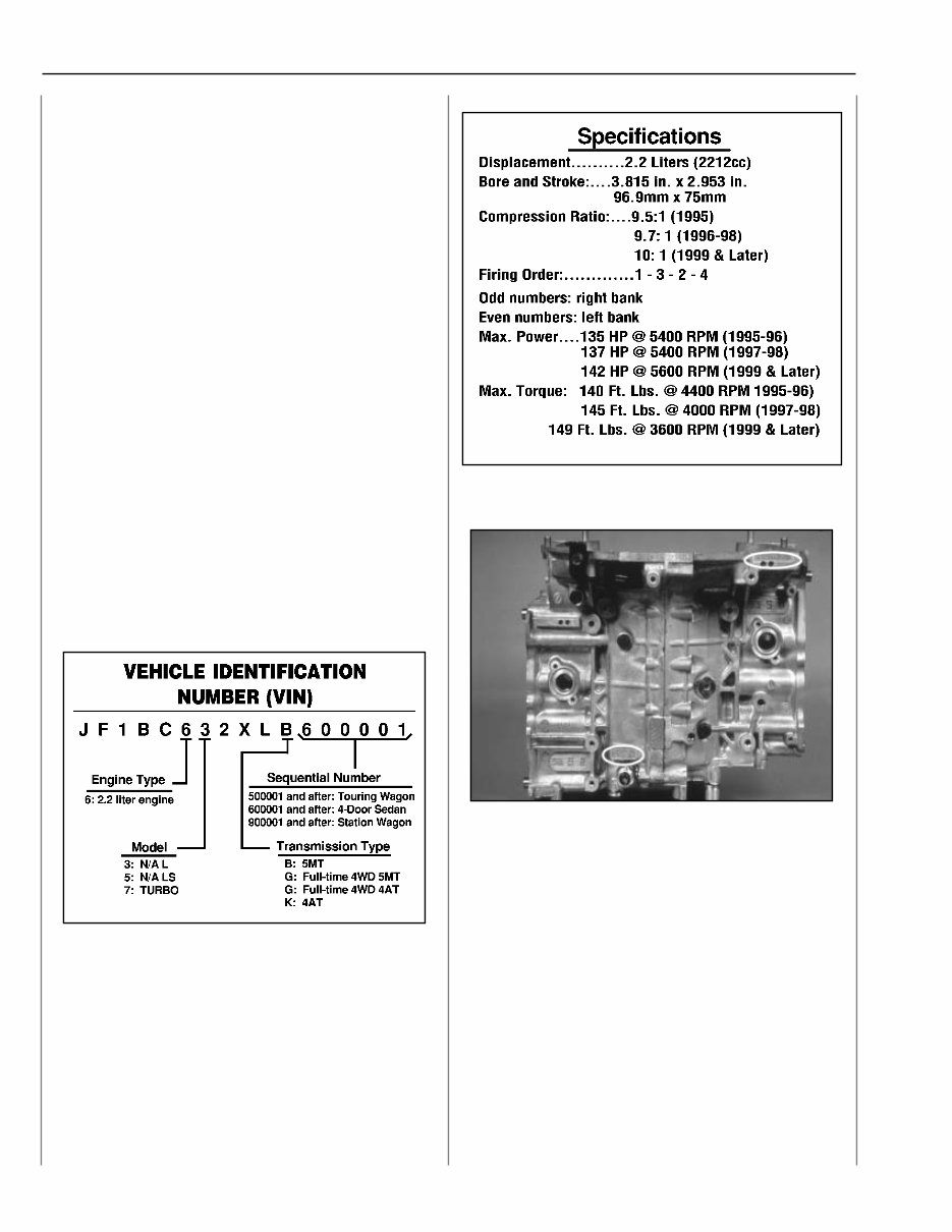
Boxer Engine Series Module 10 August 2001 Introduction This Technicians Reference Booklet introduces the Subaru 2.2 liter (SOHC) naturally aspirated (N/A), (Phase 1) and (Phase 2) engines, the 2.5 liter (DOHC) (Phase 1) and (SOHC) (Phase 2) engines, the 2.0 liter Turbo engine and the 3.0 and 3.3 liter six cylinder engines It reviews the mechanical features of these engines and the differences between existing engines. It also covers the procedures used in diagnosing and overhauling these engines. The text and illustrations are derived from and follow the classroom lectures and slide presentations and they are intended to supplement and reinforce classroom instruction and serve as a home-study reference source. A list of applicable Service Bulletins, Important Notes and Cautions, and Special Tools are given within this booklet. Pages for Diagnostic Tips and Notes are also provided. Technicians worksheets are to be completed during the hands-on lab work segments of the Boxer Engine Series Module. Always refer to the appropriate model year Subaru Service Manual and the applicable service bulletins for all specification and detailed servicing procedures. General Overview 2.2L Engine Identification Engine Identification The 2.2L engine designation is the sixth digit of the vehicle identification number (VIN). It is important to always first identify the engine before beginning diagnosis and servicing. Body type and transmission type, as well as the model year, are also information pertinent to engine diagnosis and servicing. As shown in the illustration, all this information is available from the VIN and the appropriate service manual. 2.2L N/A Engine Engine Serial and Designation Number The engine serial number is located on the machined boss on the left side of the clutch housing. The 2.2L engine designation is EJ22. 6 7 8
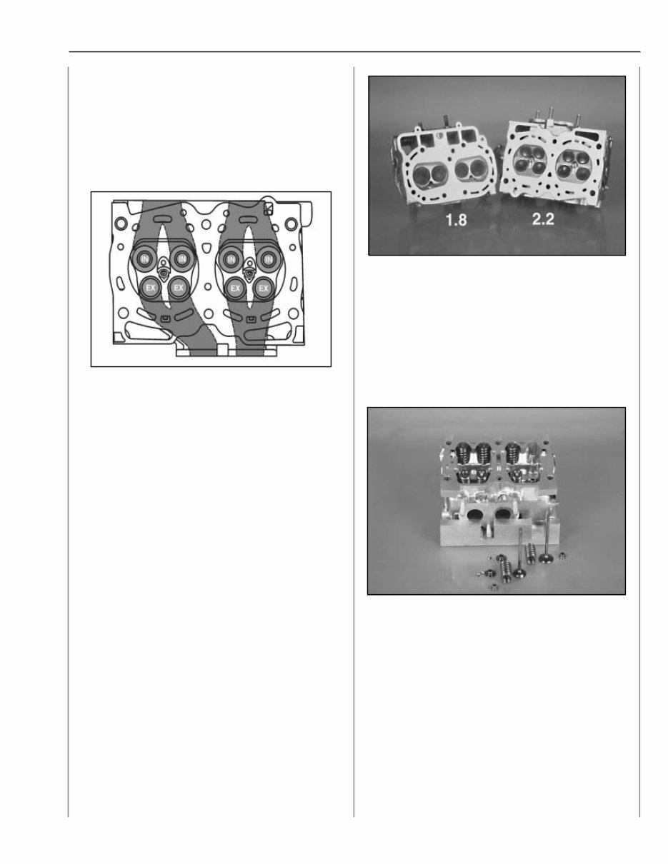
Boxer Engine Series Module 11 August 2001 2.2L Engine (Phase 1) Features The 2.2L SOHC four valves per cylinder engine is an addition to the existing Subaru "Boxer" design. The horizontally opposed, 4 stroke, 4 cylinder, liquid cooled, gasoline engine has aluminum alloy block and heads. It uses a normally aspirated MPI system. The cylinder liners are of a cast iron dry type design. Cylinder Head Design The 2.2L engine uses a cross-flow cylinder head design similar to the 1800cc OHC engine. Better breathing is provided by the two intake and two exhaust valves per cylinder which improves the intake and exhaust flow. In addition, fine-tuned high velocity intake and exhaust ports are used. The dual intake and exhaust ports are siamesed to further improve intake and exhaust flow. Combustion Chamber The 2.2L engine uses a compact pentroof combustion chamber vs the bathtub design of the 1800cc/2700cc engines. It has a centrally located spark plug which provides the quickest, most efficient combustion with a uniform flame front from the plug to the top of the piston. This, combined with the 30 degree valve angle compliments the pentroof combustion chamber shape optimizing low and medium speed torque. The cylinder heads are not interchangeable. Valve Components The valve train uses a single valve spring system vs the dual spring system of the old 1800cc engine. The intake valves are larger than the exhaust valves. The valve seal color determines location: intake seals are black, exhaust seals are brown. 10 10 10 10 10 11 11 11 11 11 12 12 12 12 12
2001 Subaru Boxer Engine Series Technician Reference Manual
Models Covered:
Subaru Legacy
Subaru Outback
Subaru Impreza
Subaru Forester
Engines Covered:
2.2L SOHC EJ22 (Phase 1 & Phase 2)
2.5L DOHC EJ25 (Phase 1)
2.5L SOHC EJ25 (Phase 2)
2.0L Turbocharged DOHC EJ20
3.0L DOHC Flat-6 EZ30
The 2001 Subaru Boxer Engine Series Technician Reference Manual provides in-depth technical details and system breakdowns for the EJ-series and EZ-series engines. This manual is tailored to the specific needs of dealership technicians and seasoned Subaru specialists working with boxer powertrains produced from the early 1990s through the early 2000s.
Whether you're diagnosing a misfire, rebuilding a cylinder head, or referencing specs for phase-based changes, this manual offers expert-level insights into combustion chamber design, valvetrain differences, timing belt routing, and torque specs. It’s an invaluable engine-focused guide for performance tuning, in-depth maintenance, and internal repair work.
Content Overview:
Engine identification & differences by phase
Valvetrain and camshaft layout diagrams
Timing belt and chain configurations
Torque specifications and tolerances
Lubrication, cooling, and intake/exhaust routing
Ignition, fuel, and emissions systems
EZ30 engine-specific diagnostics
Perfect for anyone working on or swapping Subaru Boxer engines, this technician manual delivers clarity and accuracy with manufacturer-level detail.
Printable: Yes Language: English Compatibility: Windows, macOS, Linux Requirements: PDF reader software
Recently Viewed
5,521,897Happy Clients
2,594,462eManuals
1,120,453Trusted Sellers
15Years in Business
Price:
Actual Price:
2001 Subaru Boxer Engine Series Technician Reference Manual