Subaru Robin EY15, EY20, EY28 Engine Service Repair Workshop Manual
What's Included?
Lifetime Access
Fast Download Speeds
Online & Offline Access
Access PDF Contents & Bookmarks
Full Search Facility
Print one or all pages of your manual
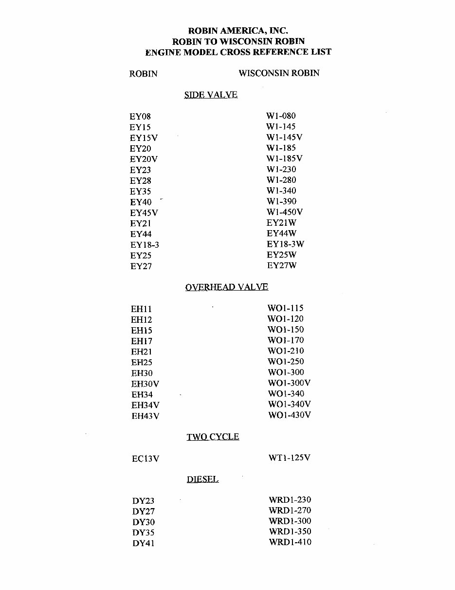
ROBIN AMERICA, INC. ROBIN TO WISCONSIN ROBIN ENGINE MODEL CROSS REFERENCE LIST ROBIN EY08 EY15 EY 15V EY20 EY2OV EY23 EY28 EY3 5 EY40 - EY45V EY2 1 EY44 EY 18-3 EY25 EY27 EH11 EH12 EH15 EH17 EH21 EH25 EH30 EH30V EH34 EH34V EH43V EC13V DY23 DY27 DY30 DY3 5 DY4 1 WISCONSIN ROBIN SIDE VALVE W 1-080 W1-145 W1-145V W1-185 W1-185V W1-230 W 1-280 W 1-340 W 1-390 Wl-45OV EY21W EY44W EY18-3W EY25W EY27W OVERHEAD VALVE WO1-115 wo1-120 WO1-150 WO1-170 wo1-210 WOl-250 WO 1-300 WO1-300V WO1-340 WO 1 -340V WO 1-43 OV TWO CYCLE WT1-125V DIESEL WRD 1-230 WRD 1-270 -1-300 WRD1-350 WRD1-410
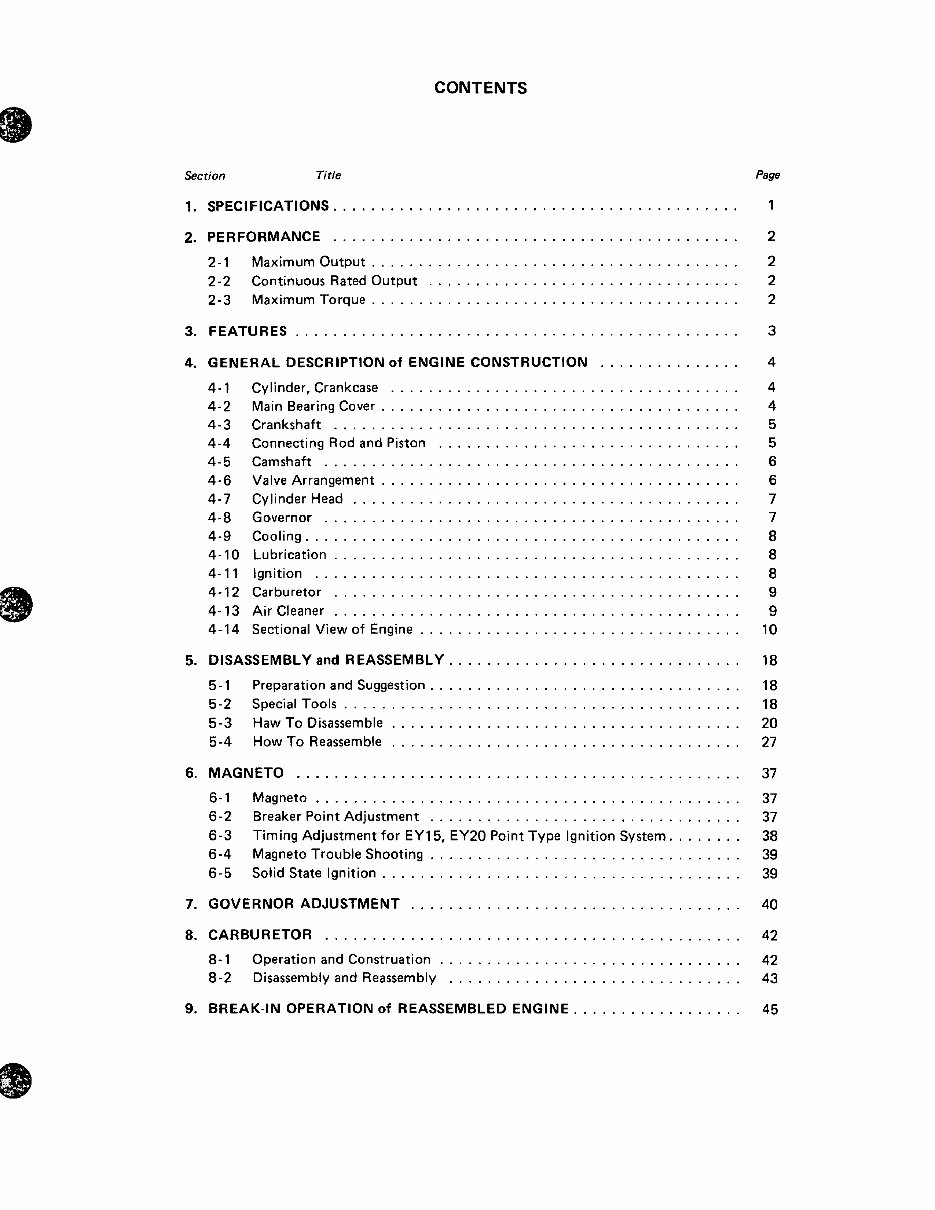
CONTENTS Section Title Page 1 . SPECIFICATIONS ........................................... 2 . PERFORMANCE ........................................... 2- 1 Maximum Output ....................................... 2-2 Continuous Rated Output ................................. 2-3 Maximum Torque ....................................... 3 . FEATURES ............................................... 4 . GENERAL DESCRIPTION of ENGINE CONSTRUCTION ............... 4- 1 4-2 4-3 4-4 4-5 4-6 4-7 4-8 4-9 4-10 4-1 1 4-12 4- 13 4-14 Cylinder. Crankcase ..................................... Main Bearing Cover ...................................... Crankshaft ........................................... ConnectingRodandPiston ................................ Camshaft ............................................ Valve Arrangement ...................................... Cylinder Head ......................................... Governor ............................................ Cooling .............................................. Lubrication ........................................... Ignition ............................................. Carburetor ........................................... Air Cleaner ........................................... Sectional View of Engine .................................. 5 . DISASSEMBLY and REASSEMBLY ............................... 5-1 Preparation and Suggestion ................................. 5-2 Special Tools .......................................... 5-3 Haw To Disassemble ..................................... 5-4 How To Reassemble ..................................... 6 . MAGNETO ............................................... 6-1 Magneto ............................................. 6-2 Breaker Point Adjustment ................................. 6-3 Timing Adjustment for EY15. EY20 Point Type Ignition System ........ 6-4 Magneto Trouble Shooting ................................. 6-5 Solid State Ignition ...................................... 7 . GOVERNORADJUSTMENT ................................... 8 . CARBURETOR ............................................ 8- 1 Operation and Construation ................................ 8-2 Disassembly and Reassembly ............................... 9 . BREAK-IN OPERATION Of REASSEMBLED ENGINE ................ 1 3 4 4 4 5 5 6 6 7 7 8 8 8 9 9 10 18 18 18 20 27 37 37 37 38 39 39 40 42 42 43 45
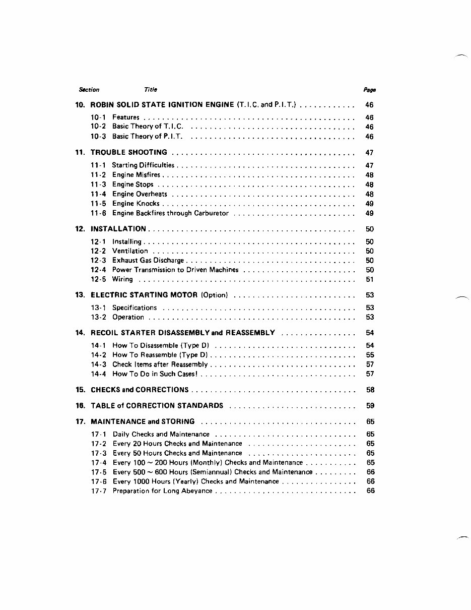
Section Title pese 10 . ROBIN SOLID STATE IGNITION ENGINE (T.I.C. and P.I.T.) ............ 46 10-1 Features ............................................. 46 10-2 Basic Theory of T . I.C. ................................... 46 10-3 Basic Theory of P . I.T. ................................... 46 11 . TROUBLE SHOOTING ....................................... 47 11 . 1 Starting Difficulties ...................................... 47 11 -2 Engine Misfires ......................................... 48 1 1-3 Engine Stops .......................................... 48 11 -4 Engine Overheats ....................................... 48 11 -6 Engine Backfires through Carburetor .......................... 49 12 . INSTALLATION ............................................ 50 12-1 Installing ............................................. 50 12-2 Ventilation ........................................... 50 12-3 Exhaust Gas Discharge .................................... 50 12-4 Power Transmission to Driven Machines ........................ 50 12-5 Wiring .............................................. 51 13 . ELECTRIC STARTING MOTOR (Option) .......................... 53 13- 1 Specifications ......................................... 53 13-2 Operation ............................................ 53 11-5 Engine Knocks ......................................... 49 14 . RECOIL STARTER DISASSEMBLY and REASSEMBLY ................ 54 14-1 How To Disassemble (Type D) .............................. 54 14-2 How To Reassemble (Type D) ............................... 55 14-3 Check Items after Reassembly ............................... 57 14-4 How To Do in Such Cases! ................................. 57 15 . CHECKS and CORRECTIONS ................................... 58 16 . TABLE of CORRECTION STANDARDS ........................... 59 17 . MAINTENANCE and STORING ................................. 17-1 Daily Checks and Maintenance .............................. 17-2 Every 20 Hours Checks and Maintenance ....................... 17-3 Every 50 Hours Checks and Maintenance ....................... 17-4 Every 100 - 200 Hours (Monthly) Checks and Maintenance ........... 17-5 Every 500 - 600 Hours (Semiannual) Checksand Maintenance ......... 17-6 Every 1000 Hours (Yearly) ChecksandMaintenance ................ 17- 7 Preparation for Long Abeyance .............................. 65 65 65 65 65 66 66 66 .
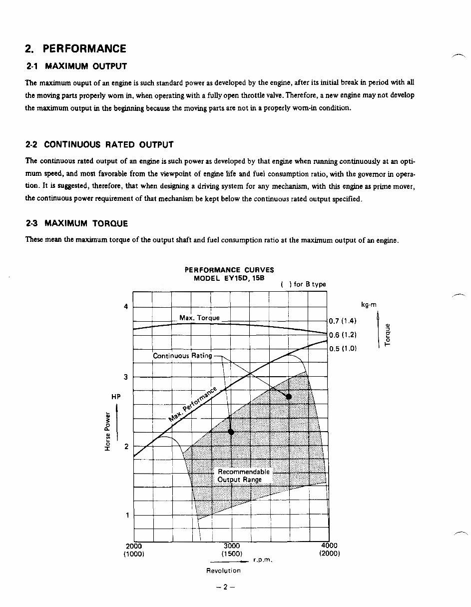
2. PERFORMANCE 2-1 MAXIMUM OUTPUT The maximum ouput of an engine is such standard power as developed by the engine, after its initial break in period with all the moving parts properly worn in, when operating with a fully open throttle valve. Therefore, a new engine may not develop the maximum output in the beginning because the moving parts are not in a properly worn-in condition. 2-2 CONTINUOUS RATED OUTPUT The continuous rated output of an engine is sudrpower as developed by that engine when running continuously at an opti- mum speed, and most favorable from the viewpoint of engine life and fuel consumption ratio, with the governor in opera- tion. It is suggested, therefore, that when designing a driving system for any mechanism, with this engine as prime mover, the continuous power requirement of that mechanism be kept below the continuous rated output specified. 23 MAXIMUM TORQUE These mean the maximum torque of the output shaft and fuel consumption ratio at the maximum output of an engine. PERFORMANCE CURVES MODEL EY15D, 15B ( 1 for B type 4 Ma;. Torque ~ 0.7 - I I 7 0.6 HP t i i I \ I I I I I I I 2000 3000 4000 (1 000) (1 500) (20001 r.p.m. Revolution kg-m -2-
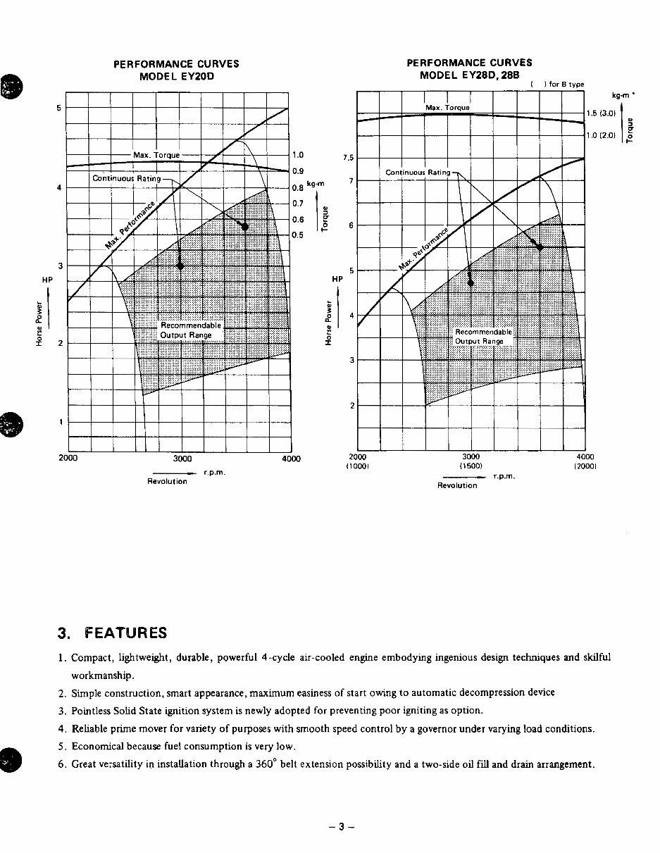
PERFORMANCE CURVES MODEL EYZOD 5 Max. Toraue 1 .o 4 3 HP L . B 2 2 w r 1 2000 3000 4000 Revolution r.p.m. 2000 (1 000) PERFORMANCE CURVES MODEL EY28D, 288 I ) for B tvm 3000 ( 15001 Revolution r.p.rn. 4000 I20001 3. FEATURES 1. Compact, lightweight, durable, powerful 4-cycle air-cooled engine embodying ingenious design techques and skilful workmanship. 2. Simple construction, smart appearance, maximum easiness of start owing to automatic decompression device 3. Pointless Solid State ignition system is newly adopted for preventing poor igniting as option. 4. Reliable prime mover for variety of purposes with smooth speed control by agovernor under varying load conditions. 5. Economical because fuel consumption is very low. 6. Great ve:satility in installation through a 360" belt extension possibihty and a two-side oil fill and drain arrangement. -3-
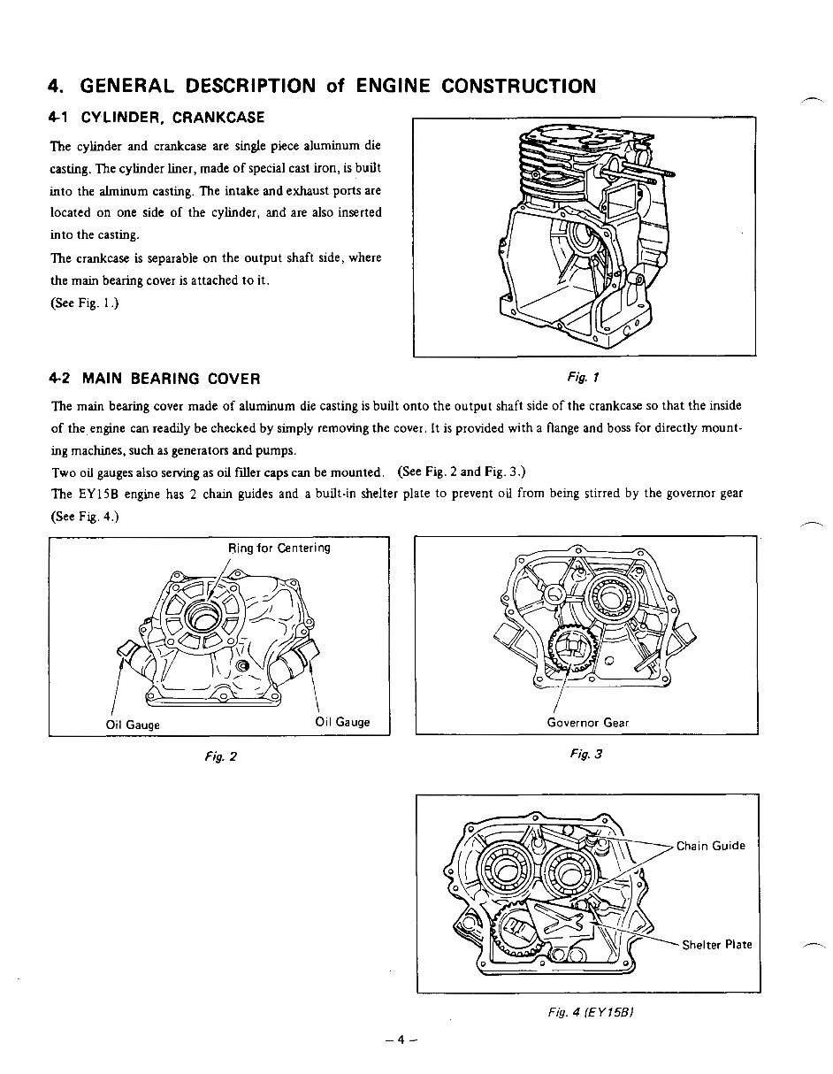
4. GENERAL DESCRIPTION of ENGINE CONSTRUCTION 4-1 CYLINDER, CRANKCASE The cylinder and crankcase are single piece aluminum die casting. The c y h d e r liner, made of special cast iron, is built into the alminum casting. The intake and exhaust ports are located on one side of the cyhder, and are also inserted into the casting. The crankcase is separable on the output shaft side, where the main bearing cover is attached to it. (See Fig. 1 .) 4-2 MAIN BEARING COVER Fig. 1 The main bearing cover made of aluminum die casting is built onto the output shaftside of the crankcase so that the inside of the engine can readily be checked by simplyremoving the cover. It is provided with a flange and boss for directly mount- ing machmes, such as generators and pumps. Two oil gauges also serving as oil filler caps can be mounted. (See Fig. 2 and Fig. 3.) The EY 15B engine has 2 chain guides and a built-in shelter plate to prevent oil from being stirred by the governor gear (See Fig. 4.) Ring for Centering / Oil Gauge Oil Gauge Fig. 2 I Governor Gear Fig. 3 Chain Guide - Shelter Plate 1 Fig. 4 (E Y 15B) -4-
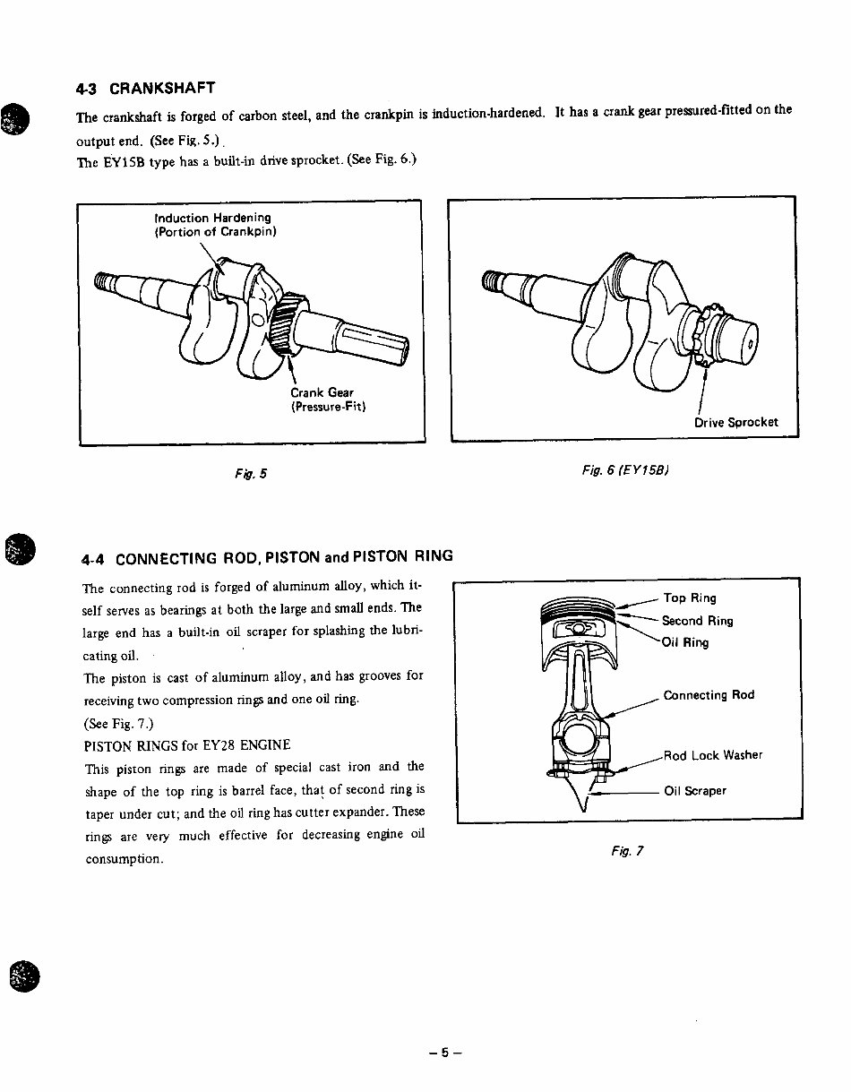
4-3 CRANKSHAFT The crankshaft is forged of carbon steel, and the crankpin is induction-hardened. It has a crank gear premred-fitted on the output end. (See Fig. 5.). "he EY 15B type has a built-in drive sprocket. (See Fig. 6.) Induction Hardening (Portion of Crankpin) Crank Gear (Pressure-Fit) Drive Sprocket - Fig. 5 Fig. 6 (E Y 158) 4-4 CONNECTING ROD, PISTON and PISTON RING The connecting rod is forged of aluminum alloy, which it- self serves as bearings at both the large and small ends. The large end has a built-in oil scraper for splashing the lubri- cating oil. The piston is cast of aluminum alloy, and has grooves for receiving two compression rings and one oil ring. (See Fig. 7.) PISTON RINGS for EY28 ENGINE This piston rings are made of special cast iron and the shape of the top ring is barrel face, that of second ring is taper under cut; and the oil ring has cutter expander.These rings are very much effective for decreasing engine oil consumption. Connecting Rod Rod Lock Washer Oil Scraper 1 Fig. 7 -5-
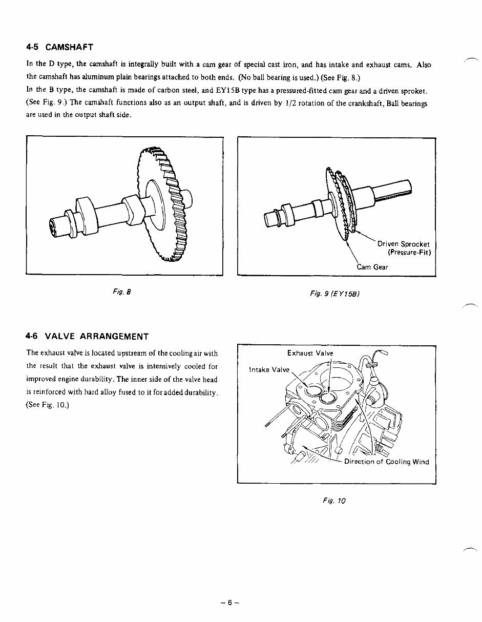
4-5 CAMSHAFT In the D type, the camshaft is integrally built with a cam gear of special cast iron, and has intake and exhaust cams. Also the camshaft has aluminum plain bearings attached to both ends. (No ball bearing is used.) (See Fig. 8.) In the B type, the camshaft is made of carbon steel, and EYlSB type has a pressured-fitted cam gear and a driven sproket. (See Fig. 9.) The camshaft functions also as an output shaft, and is driven by 1/2 rotation of the crankshaft, Ball bearings are used in the output shaft side. J Fig. 8 4-6 VALVE ARRANGEMENT The exhaust vahe is located upstream of the coolingair with the result thattheexhaust valve is intensiveiy cooled for improved engine durability. The inner side of the valve head is reinforced with hard alloy fused to it for added durability. (See Fig. 10.) Driven Sprocket (Pressure-Fit) Cam Gear Fig. 9 (E Y 156) I Exhaust Valve Direction of Cooling Wind Fig. 70 -6-
This is a comprehensive factory service repair workshop manual for the Subaru Robin EY15, EY20, EY28 Engine. The manual features easy-to-read text sections with high-quality diagrams and instructions, making it suitable for both do-it-yourself enthusiasts and experienced mechanics. It includes step-by-step instructions and detailed exploded pictures and diagrams to effectively and efficiently complete the required job.
Models Covered:
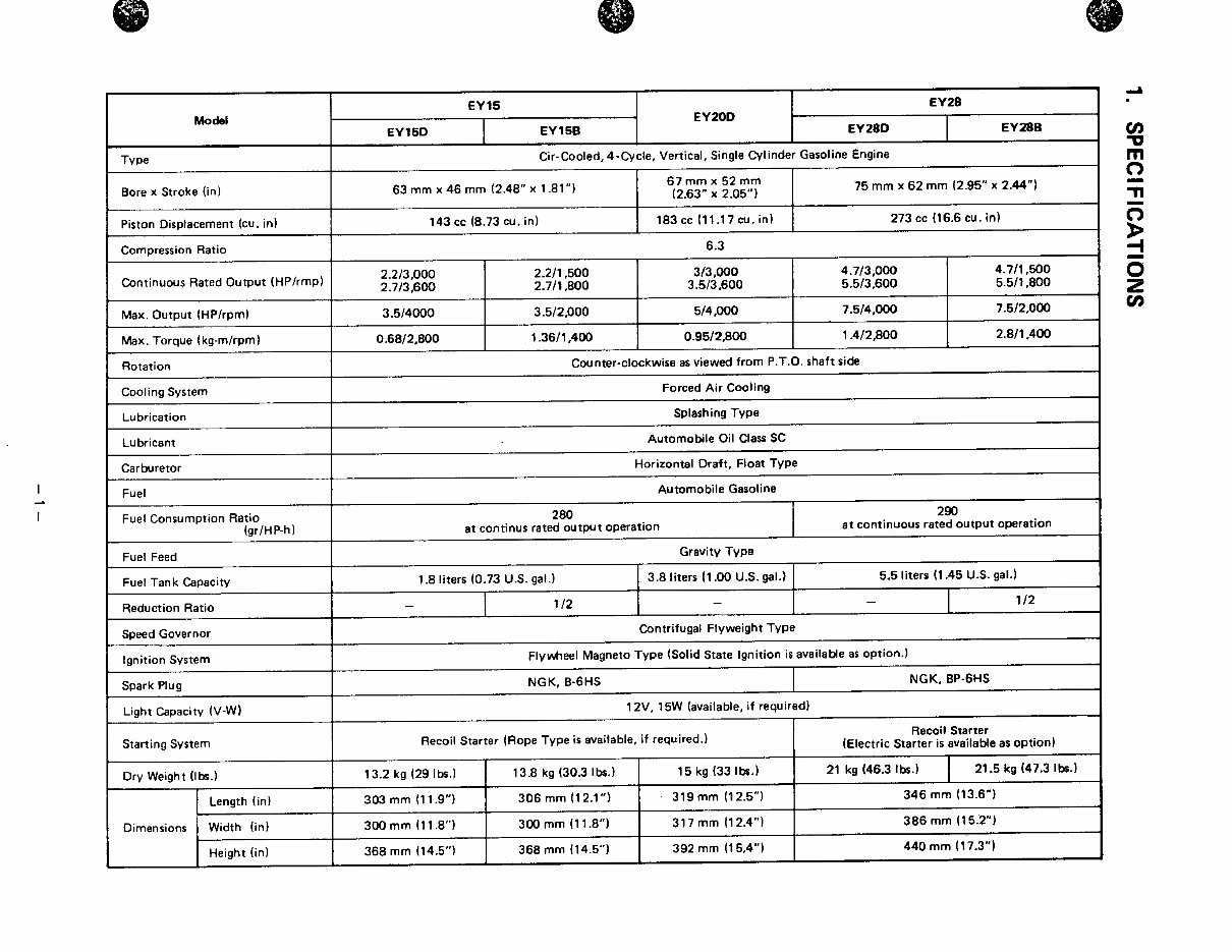
Cir-cooled, 4-cycle, Vertical, Single Cylinder Gasoline Engine
Subaru Robin EY15 Engine: EY15D, EY15B
Subaru Robin EY20 Engine: EY20D
Subaru Robin EY28 Engine: EY28D, EY28B
Service Repair Manual Covers:
SPECIFICATIONS
PERFORMANCE
FEATURES
GENERAL DESCRIPTION OF ENGINE COMPONENTS
DISASSEMBLY AND REASSEMBLY
MAGNETO
GOVERNOR ADJUSTMENT
CARBURETOR
BREAK-IN OPERATION OF REASSEMBLED ENGINE
ROBIN SOLID STATE IGNITION ENGINE
TROUBLESHOOTING
INSTALLATION
ELECTRIC STARTING MOTOR
RECOIL STARTER DISASSEMBLY AND REASSEMBLY
CHECKS AND CORRECTIONS
TABLE OF CORRECTION STANDARDS
MAINTENANCE AND STOPPING
And More......
File Format: .PDF
Compatibility: All Versions of Windows & Mac
Language: English
Requirements: Adobe Reader & WinZip
This Subaru Robin EY15, EY20, EY28 Engine Service Repair Workshop Manual is printable, eliminating the need for postage and packaging, thus saving you money. It is a valuable resource to have for maintaining your vehicle.
Recently Viewed
5,521,897Happy Clients
2,594,462eManuals
1,120,453Trusted Sellers
15Years in Business
Price:
Actual Price:
Subaru Robin EY15, EY20, EY28 Engine Service Repair Workshop Manual