

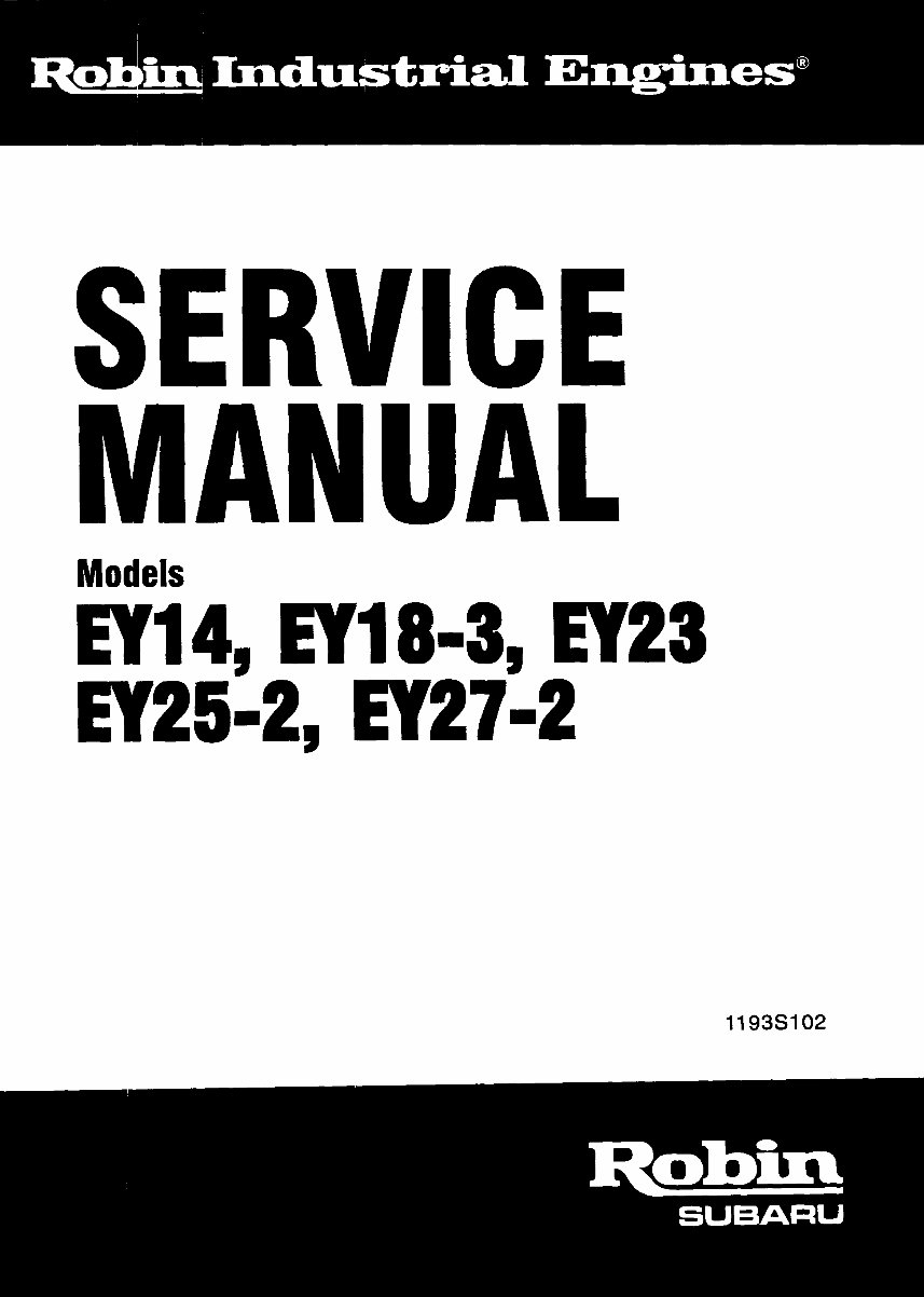
Robin EY14, EY18-3,EY23, Ey25-2, EY27-2 service manual
What's Included?
Fast Download Speeds
Online & Offline Access
Access PDF Contents & Bookmarks
Full Search Facility
Print one or all pages of your manual

ROBIN AMERICA, mc.
ROBIN TO WISCONSIN ROBIN
ENGINE MODEL CROSS REFERENCE LIST
ROBIN WISCONSIN ROBIN
-
EY08
EYl5
EY 15V
EY20
EY2OV
EY23
EY28
EY35
EY40
EY45V
EY2 1
EY44
EY25
EY27
EY 18-3
EHl 1
EH12
EH15
EH17
EH21
EH25
EH30
EH3OV
EH34
EH34V
EH43V
EC13V
DY23
DY27
DY30
DY35
DY4 1
W1-080
W1-145
W1-145V
w1-185
W1-185V
Wl-230
W 1-280
W1-340
W1-390
W1-450V
EY21W
EY44W
EY 18-3W
EY25W
EY27W
TWO CYCLE
WOl-115
WOl-120
WO1-150
WO1-170
wo1-210
WO1-250
WO 1-300
WO 1 -300v
WO 1-340
WO 1 -340V
WO 1 -430V
WT1-125V
WRD 1-230
WRD 1-270
WRD 1-300
WRD1-350
wRDl-410
CONTENTS
Section Title Page
...........................................
1 . SPECIFICATIONS 1
2 . PERFORMANCE ........................................... 2
2-1 Maximum Output ........................................ 2
2-2 Continuous Rated Output .................................. 2
2-3 MaximumTorque and Fuel Consumption Ratio at Max . Output ......... 2
3 . FEATURES ................................................ 4
4 . GENERAL DESCRIPTION of ENGINE CONSTRUCTION ............... 4
4-1 Cylinder Crankcase ...................................... 4
4-2 Main Bearing Cover ....................................... 4
4-3 Crankshaft ........................................... 4
4-5 Camshaft ............................................. 4
4-7 Cylinder Head .......................................... 5
4-8 Governor ............................................. 5
4-9 Cooling ............................................... 5
4-10 Lubrication ............................................ 5
4-11 Ignition .............................................. 5
4-13 Air Cleaner ............................................ 5
4-14 Sectional View of Engine ................................... 6
4.4 Connecting Rod and Piston ................................. 4
4-6 Valve Arrangement ....................................... 5
4-12 Carburetor ............................................ 5
5.lNSTALLATlON ............................................ 14
5-1 Installing .............................................. 14
5-2 Ventilation ............................................ 14
5-3 Exhaust Gas Evacuation .................................... 14
5-4 Fuel System ........................................... 14
5-5 Power Transmission to Driven Machines ......................... 14
5-6 Wiring ............................................. 15
6 . DISASSEMBLY and REASSEMBLY .............................. 21
6-1 Preparation and Suggestions ................................. 21
6-2 Special Tools ........................................... 21
6-3 Disassembly and Ressembly Procedures ......................... 22
7.MAGNETO ................................................ 29
7-1 Magneto ............................................. 29
7-2 Breaker Point Adjustment .................................. 29
74 Magneto Trouble Shooting ................................... 31
7-3 Timing Adjustment ....................................... 30
8 . GOVERNOR ADJUSTMENT ................................... 32
9. CARBURETOR ............................................. 33
9-1 Operation and Construction ................................. 33
9-2 Disassembly and Reassembly ................................ 34
9-3 Adjustment ............................................ 36
10 . RUN-INOPERATION of REASSEMBLED ENGINE ................... 37
11 . TROUBLE SHOOTtNG ....................................... 38
11 -1 Starting Difficulties ....................................... 38
11 -2 Engine Misses ........................................... 39
11-3 Engine Stops ........................................... 39
114 Engine Overheats ........................................ 39
11-5 Engine Knocks ......................................... 40
11-6 Engine BackfiresThroughCarburetor ........................... 40
12 . CHECKS AND CORRECTIONS ................................. 41
13 . CORRECTION TABLE ....................................... 42
14 . MAINTENANCE and STORING ................................. 48
14-1Daily Checks and maintenance(Every 8 Hours) .................... 48
14-2 Every 20 Hours Checks and Maintenance ........................ 48
14-3 Every 50 Hours (10 Day) ChecksandMaintenance .................. 48
14-4 Every 100 . 200 Hours (Monthly) Checks and Maintenance ............ 48
14-5 Every 500 . 600 Hours (Semianual) Checksand Maintenance ........... 49
14-6 Every 1000 Hours (Yearly) Checks and Maintenance ................. 49
14-7 Preparation forLong-Term Storage ............................ 49
1. SPEC1 FICATIONS
[ N
m
p 5 2 0
n
0 "
V
t
1
c
t
I
I
i
-1 -

2. PERFORMANCE
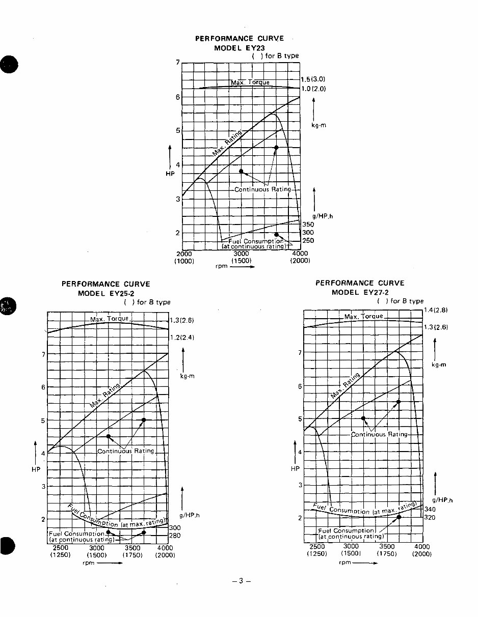
2-1 MAXIMUM OUTPUT n
The Maximum output of an engine is such standard power as developed by that engine, after its
initial run-in period with all the moving parts properly worn-in, when operating with the fully
openthrottlevalve.Therefore,it follows that a newenginemaynotdevelopthismaximum
output in the beginning, because moving parts are not in a properly worn-in condition.
2-2 CONTINUOUS RATED OUTPUT
The continuous rated output of an engine is such power as developed by that engine when
running at anoptimumspeedmostfavorablefromthepointofviewofenginelifeandfuel
consumption ratio. Therefore, it follows that when designing a driving system for any
mechanism, with a model EY14, EY18-3, EY23, EY25-2 and EY27-2 engine, as a prime mover,
the continuous power requirement of that mechanism must be kept below the continuous rated
output specified.
2-3 MAXIMUM TORQUE and FUEL CONSUMPTION RATIO AT MAX. OUTPUT
The maximum torque of an engine is that driving torque of the driving shaft at which the engine
is driving an external load, while the engine is developing its max. output. The fuel
consumption ratio at max. output is that fuel consumption ratio of an engine while that engine
is running at the rnax. output.
PERFORMANCE CURVE PERFORMANCE CURVE
MODEL EY18-38
-2-
PERFORMANCE CURVE
MODEL EY23
7
( ) for B type
1.5(3.0)
1.0 (2.0)
6
I
5
kg-m
HP I 4
3
I
g1HP.h
3 50
2 300
250
2000 3000 4000
(1 000) (1 500) (2000)
rpm __c
PERFORMANCE CURVE
MODEL EY25-2
( ) for B type
.h
PERFORMANCE CURVE
MODEL EY27-2
( ) for 8 type
1.4(2.8)
1.3(2.6)
7 I
kg-m
6
5
HP I4
3
I
g1HP.h
340
2 320
2500 3000 3500 4000
(1250) (1500)
(1750) (2000)
rpm -
-3 -

FEATURES
A compact, lightweight and durable 4-cycle air-cooled engine with high power output,
embodying ingenious design technique and advanced production skill. n
Simple construction, smart appearance, easy start.
Reliable power for wide. variety of purposes, with smooth speed controll by a governor,
under varying load conditions.
Economical advantage through low fuel consumption.
Great versatility in installation through a 360° belt extension possibility and a two side oil
fill and drain arrangement.
GENERAL DESCRIPTJON of ENGINE CONSTRUCTION
CYLINDER, CRANKCASE
The cylinder and the crankcase are die-cast as a compact aluminium mono-block piece. The
cylinder liner and the valve seats are made of special alloy cast iron and are imbedded in the
aluminium casting as inserts. The intake and exhaust ports are located at one side of the
cylinder and are also made of inserted pieces in the casting.
The crankcase is separable at the driving shaft side and this separable piece constitutes the
main bearing cover.
4-2 MAIN BEARING COVER
As the aluminium die-cast main bearing cover is built onto the crankcase on the driving shaft
side, the engine 'inside are reached for inspection, easily by simply removing it. It is also
provided with a flange and boss for directly mounting operating machines such as generators
and pumps.
There are two oil filters serving also as oil gauges provided at two locations.
(However, in EY18-3 or EY23 engine, at one location in the carburetor side.)
4-3 CRANKSHAFT
The crankshaft is machined from a carbon steel forging with an induction hardened crank pin.
On the fan side, the breaker cam is provided and on the driving side, the crankshaft gear is
force-fit.
44 CONNECTING ROD and PISTON
The connecting rod is machined from an aluminium alloy forging in which the forged alloy itself
serves as the bearing metal at both ends. On the large end, an oil scraper for splashing the
lubricating oil is provided.
The piston is machined from an aluminium alloy casting and is provided with two grooves for
compression rings and one groove for the oil ring.
4-5 CAMSHAFT
The camshaft is machined from a carbon steel forging with integral intake and exhaust cams
and is provided with a force-fit cam gear. In the model B engine, the camshaft serves also as
the driving shaft, being driven at half the crankshaft speed. In the EY14D, EY23D, EY25-2D
and EY27-2D engines, the camshaft is machined from a special alloy cast iron with an integral
camshaft gear, and is supported by aluminium bearing metals machined integral with the
crankcase at both ends. (no ball bearing is used)
n
-4 -
4-6 VALVE ARRANGEMENT
The exhaust valve is positioned in the upstream side of the cooling air with the result that the
exhaust valve is intensively cooled for engine life improvement.
-
4-7 CYLINDER HEAD
A Ricardo type combustion chamber of ample area is employed for good combustion efficiency.
The spark plug is mounted obliquely to facilitate fuel tank mounting.
4-8 GOVERNOR
The flyweight type governor effectivelyoperatesto maintain the selected speed at varying
load.
The model EY14, EY18-3 and EY23 engine is equipped with a separate gearing for the governor
to secure better performance.
4-9 COOLING
Cooling is accomplished by a flow of air circulated past the cylinder walls and head fins from a
combination fan-flywheel. The air is guided by a cylinder buffle and a head cover. The EY14,
EY18-3, EY23, EY25-2 and EY27-2 engines are equipped with curved vane fans made in two
modifications, each for direct drive and reduction drive engines.
4-10 LUBRICATION
Lubrication for rotating and sliding parts is accomplished by scooping and splashing the oil in
the crankcase with oil scraper attached to connecting rod.
4-11 IGNITION
The ignition system is of the flywheel magneto type with the ignition timing set 230 before
T.D.C. The magneto comprises a flywheel, ignition coil and a breaker, of which the flywheel
(serving also as a fan) is mounted on the crankshaft and the two other members are mounted
directly in the crankcase. (for details, refer to 7. MAGNETO section)
The model EY23 engine normally incorporates an electronic ignition system.
4-12 CARBURETOR
A horizontal draft carburetor is employed. Its setting has been carefully determined after
through testing to achieve best starting, accelerating, fuel consumption, output and other
performances.
For other details such as construction, refer to 9. CARBURETOR section.
4-13 AIR CLEANER
The model EY 14, EY18-3 and EY23 engines are equipped with an oval air cleaner incorporating
8 sponge element.
The cycl.one type air cleaner with a semi-wet double element is optional.
The model EY25-2, EY27-2 engines are equipped with an cyclone type semi-wet double element
air cleaner.
-5-
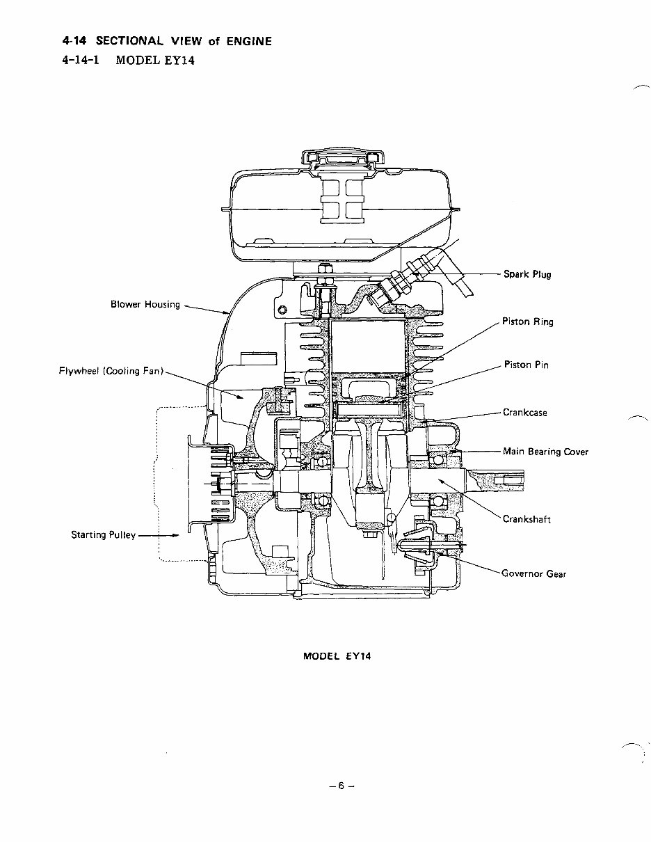
4-14 SECTIONAL VIEW of ENGINE
4-14-1 MODEL EY14
FI
Blower
ywheel (Cooling
Housing
Starting Pulley-
MODEL EY14
ver
-6-
You're Reading a Preview
What's Included?
Fast Download Speeds
Online & Offline Access
Access PDF Contents & Bookmarks
Full Search Facility
Print one or all pages of your manual
$27.99
Viewed 67 Times Today


Secure transaction
What's Included?
Fast Download Speeds
Online & Offline Access
Access PDF Contents & Bookmarks
Full Search Facility
Print one or all pages of your manual
$27.99
This is the complete factory service repair workshop manual for the Robin EY14, EY18-3, EY23, EY25-2, EY27-2. This Service Manual has easy-to-read text sections with top quality diagrams and instructions. It provides step-by-step instructions based on the complete disassembly of the machine, including highly detailed exploded pictures and diagrams to show you how to complete the required job correctly and efficiently.
Service Repair Manual Covers:
- SPECIFICATIONS
- PERFORMANCE
- FEATURE
- GENERAL DESCRIPTION
- INSTALLATION
- DISASSEMBLY AND REASSEMBLY
- ENGINE OIL
- MAGNETO
- GOVERNOR ADJUSTMENT
- CARBURETOR
- BREAK IN OPERATION
- TROUBLESHOOTING
- INSTALLATION
- CHECKS AND CORRECTIONS
- TABLE OF CORRECTION STANDARD
- MAINTENANCE AND STORAGE
- And More......
File Format: .PDF manual


