02:01 Issue 7.0 en-GB
© Scania CV AB 2018, Sweden
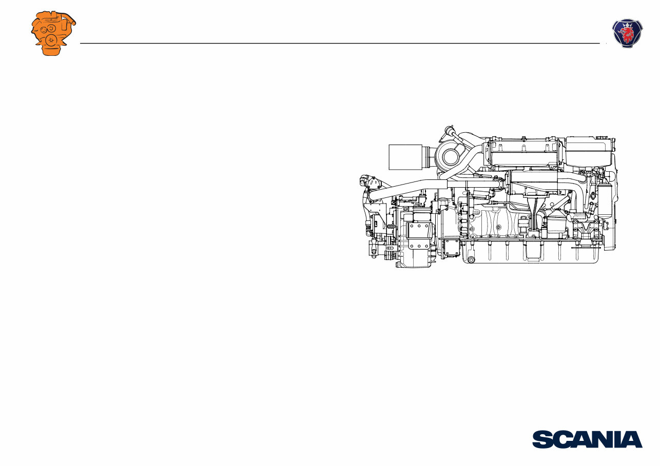
Installation manual
Engine
Marine engines
DI09, DI13, DI16
393 926
INSTALLATION
MANUAL
© Scania CV AB 2018, Sweden
02:01 Issue 7.0 en-GB 2
Changes from the previous issue ............................................................................ 3
Engine suspension .................................................................................................... 4
Suspension design requirements ......................................................................... 4
Rigid engine suspension ...................................................................................... 6
Flexible engine suspension .................................................................................. 6
Suspension of reverse gear .................................................................................. 8
Tightening torque for engine suspension ............................................................ 9
Permissible installation and operating angles ................................................... 10
Flywheel housing .............................................................................................. 11
Lifting the engine .............................................................................................. 12
Engine bed ......................................................................................................... 15
Accessibility for maintenance and repairs .......................................................... 16
Installation requirements ................................................................................... 16
Clearances ......................................................................................................... 17
Engine alignment ................................................................................................... 18
Aligning engine and shafts ................................................................................ 19
Power transmission ............................................................................................... 24
Flexible coupling ............................................................................................... 24
Friction clutch ................................................................................................... 24
Transmission types ................................................................................................ 25
Mechanical transmissions ................................................................................. 25
Belt transmissions ............................................................................................. 25
Power take-off ........................................................................................................ 27
Front-mounted power take-offs ......................................................................... 28
Side-mounted power take-offs .......................................................................... 30
Calculation example for torque take-off from power take-off .......................... 37
Connection of sensors for external monitoring systems .................................... 37
DI09 and DI13 .................................................................................................. 38
DI16 .................................................................................................................. 40
Torsional oscillations ............................................................................................ 42
Data for torsional oscillation calculation .......................................................... 42
Torsional oscillation calculations from Scania ................................................. 43
General tightening torques for screw joints ....................................................... 44
Specification of normal tightening torques ....................................................... 44
Tightening torques ............................................................................................ 45
INSTALLATION
MANUAL
© Scania CV AB 2018, Sweden
Changes from the previous issue
02:01 Issue 7.0 en-GB 3
Changes from the previous issue
The changes made in this document compared with the previous issue are marked
with a black line in the left-hand margin. The changes are also described below.
• In section Suspension design requirements there is a clarification that the suspen-
sion should be as rigid as possible. In addition, example illustrations of suspen-
sion for engines with marine transmission have been added.
• In section Insulators , maximum and minimum loads and dimensions for Scania
insulators have been added.
• In section Tightening torque for engine suspension , a tightening sequence for the
engine brackets has been added.
• The conditions for propeller installation without a separate thrust bearing have
been clarified in section Flywheel housing .
• Working procedures for Lifting the engine have been added.
• Section Flexible coupling has been made clearer.
• In section Power take-off , a text and illustration has been added, informing the
reader that components from other manufacturers cannot be used in the belt trans-
mission.
• Hydraulic diagram for hydraulic pump has been added.
• Calculation example for torque take-off from power take-off has been added.
• In section Data for torsional oscillation calculation , information has been added
on what values Scania needs in order to approve an external torsional oscillation
calculation.
INSTALLATION
MANUAL
© Scania CV AB 2018, Sweden
Engine suspension
02:01 Issue 7.0 en-GB 4
Engine suspension
Suspension design requirements
The type of engine suspension that is appropriate varies for different engine installa-
tions. In general, the following applies:
• The engine suspension should be designed for the forces it is exposed to, both
continuously and momentarily during operation. Such forces are reaction forces
from the transmitted torque and in some cases longitudinal acceleration, retarda-
tion and reaction forces in the engine.
• Both the engine suspension and the engine bed should be designed so that there
are no resonant oscillations within the engine speed range. They should also be
designed so that annoying vibrations from the engine are not transmitted to the
surroundings.
• The engine suspension and engine bed should be designed in a way which allows
access for maintenance and repairs.
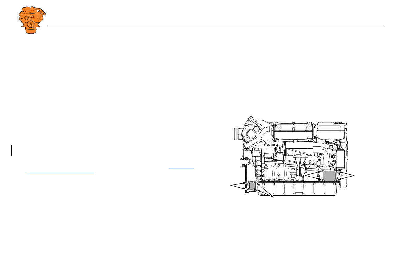
• The suspension should be as rigid as possible. Use all 4 screw holes in the cylinder
block and flywheel housing for the respective engine bracket. See illustration.
• The engine bed location and the engine suspension must be designed so that the
permissible angles of inclination for the engine are not exceeded. See Permissible
installation and operating angles .
393 929
INSTALLATION
MANUAL
© Scania CV AB 2018, Sweden
Engine suspension
02:01 Issue 7.0 en-GB 5
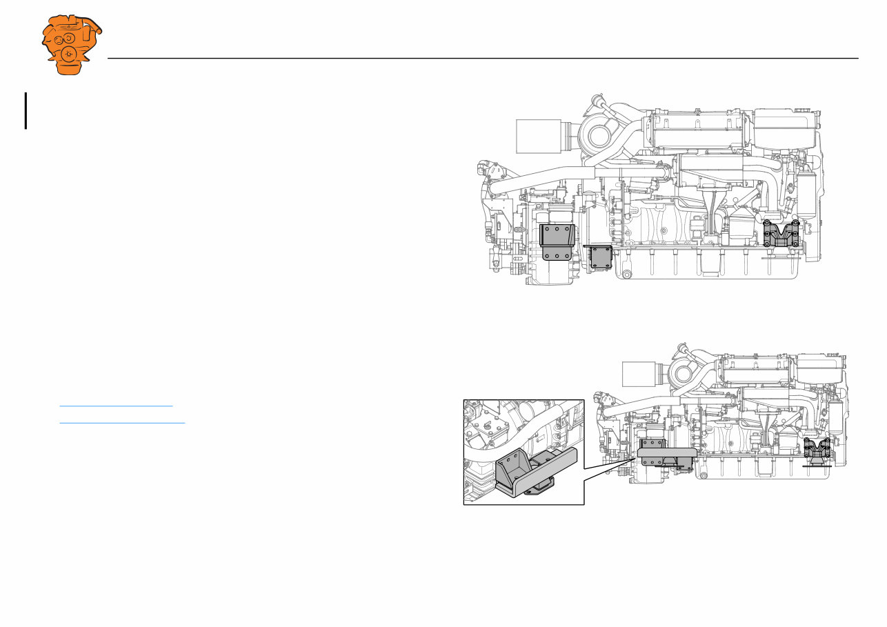
• For engines with marine transmission, Scania recommends a six-point suspension
or four-point suspension with a common rear bracket for pipes, transmission and
engine. See the illustrations.
There are two standard engine suspension designs:
• Rigid engine suspension
• Flexible engine suspension
393 925
Example of six-point suspension.
393 927
Example of four-point suspension with common rear bracket.
INSTALLATION
MANUAL
© Scania CV AB 2018, Sweden
Engine suspension
02:01 Issue 7.0 en-GB 6
Rigid engine suspension
A rigid engine suspension can absorb greater forces in all directions than flexible en-
gine suspension. It requires highly accurate alignment of the engine in relation to the
driven unit. On the other hand, it requires no special flexibility in the hoses, pipes and
controls connected to the engine.
A rigid engine suspension can be used in engine installations where vibration causes
no significant problems and where other characteristics make it desirable.
Even with a rigid engine suspension, the transmission of vibration to the engine bed
can be kept low if the masses of the engine bed and connected parts are large in re-
lation to the mass of the engine.
It is also possible to construct flexible engine suspension between the frame and the
engine bed to reduce the transmission of vibration to the engine bed.
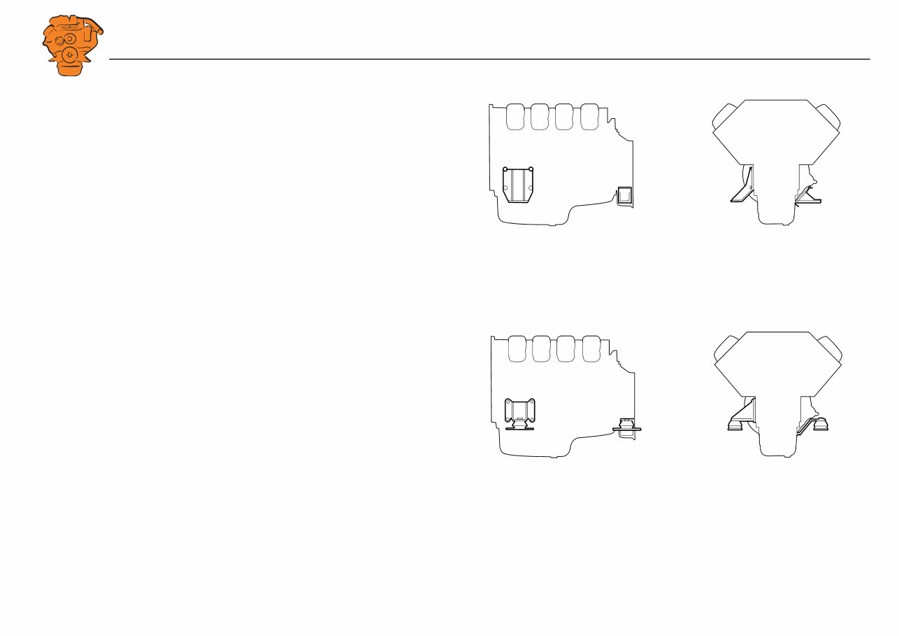
Flexible engine suspension
Flexible engine suspension dampens vibrations more effectively than rigid engine
suspension. It prevents extreme movement between engine and engine bed during vi-
olent ship movement. Flexible engine suspension can also absorb some level of re-
action force from the propeller. Flexible engine suspension does not require such
careful alignment of the engine as rigid engine suspension.
However, flexible engine suspension does not absorb longitudinal and lateral forces
in the engine to the same extent as rigid engine suspension.
344 281
Examples of rigid engine suspension.
334 280
Examples of flexible engine suspension.
INSTALLATION
MANUAL
© Scania CV AB 2018, Sweden
Engine suspension
02:01 Issue 7.0 en-GB 7
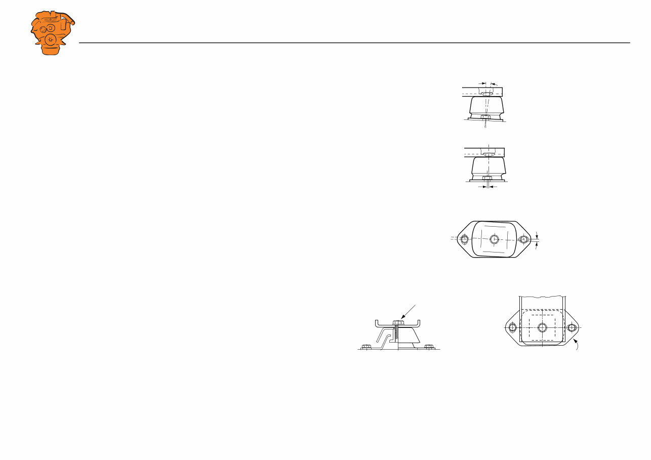
Insulators
Cushyfloat insulators with hardness 55 or 65 Shore can be ordered as option. The fol-
lowing applies for these parts:
• The engine bracket and frame or engine bed should be parallel.
• The vertical centre lines should coincide laterally.
• The upper and lower parts of the insulators should be parallel longitudinally.
Tightening torque. Hardness marking.
max 1°
396 084
0
396 085
55
0°
396 086
310 404
160±10 Nm
310 405
55
55
alt. 65
INSTALLATION
MANUAL
© Scania CV AB 2018, Sweden
Engine suspension
02:01 Issue 7.0 en-GB 8
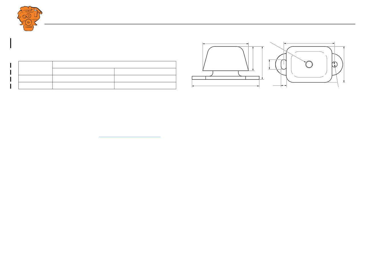
The illustration shows the dimensions of the insulators. The illustration applies to
both 55 and 65 Shore.
Suspension of reverse gear
Built-on reverse gear can either have separate brackets or suspension attachments
which are integrated with the engine. See Suspension design requirements .
Contact Scania or the supplier of the reverse gear about approved type of suspension
for reverse gear.
Shore
Vertical load (kg), DI09, DI13, DI16
Min. Max.
55 205 340
65 300 500
140
185
67
15
27
126
A
99
Ø 15
M20
394 807
Insulators 55 and 65 Shore.
Dimension A: Without load = 91 mm. With load = 86 mm.
INSTALLATION
MANUAL
© Scania CV AB 2018, Sweden
Engine suspension
02:01 Issue 7.0 en-GB 9
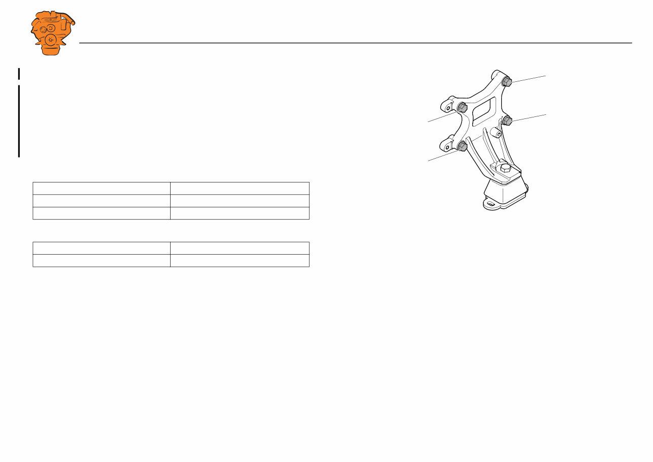
Tightening torque for engine suspension
The engine brackets can look different on different engine types, but all types of en-
gine bracket are tightened crosswise.
1. Torque tighten screws 1 and 2.
2. Torque tighten screws 3 and 4.
3. Angle-tighten screws 1 and 2.
4. Angle-tighten screws 3 and 4.
Front engine suspension
Rear engine suspension
Type of screw Tightening torques
25 mm clamping length, M16, 10.9 130 Nm, 90°
50 mm clamping length, M16, 10.9 130 Nm, 135°
Type of screw Tightening torques
M14, 8.8 149 Nm
1
3
4
2
394 815
Example of engine bracket.
INSTALLATION
MANUAL
© Scania CV AB 2018, Sweden
Engine suspension
02:01 Issue 7.0 en-GB 10
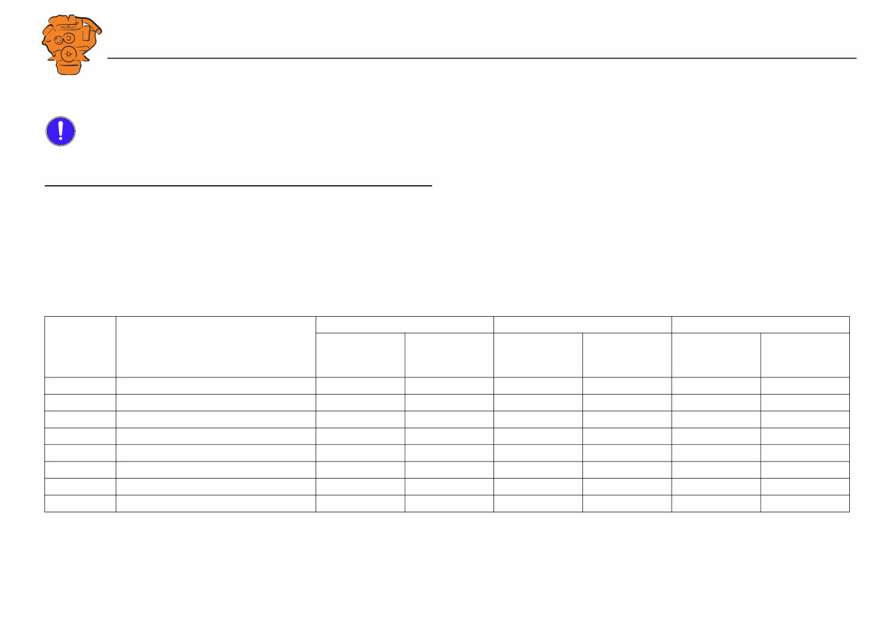
Permissible installation and operating angles
IMPORTANT!
If the angles of inclination are exceeded, lubrication system performance will deteri-
orate, which can cause damage to the engine or reduce its service life.
Maximum installation angle means maximum permissible installation angle for an
engine relative to the horizontal plane. The angle indicates the limit for engine incli-
nation during continuous operation.
Maximum operating angle means maximum permissible angle of inclination for an
engine in operation and with minimum oil level. The angle may only be used for
short periods. The maximum forward or rearward operating angles are not applicable
to their full extent if the engine is inclined laterally at the same time.
Engine type Type of oil sump Max. installation angle Max. operating angle Oil capacity (litres)
Inclination rear-
wards and for-
wards
Inclination lat-
erally
Inclination rear-
wards and for-
wards
Inclination lat-
erally
Min. Max.
DI09 Deep front, without ladder frame 12° 12° 30° 30° 32 38
DI09 Low, without ladder frame 12° 12° 20° 30° 25 32
DI13 Deep front, with ladder frame 12° 12° 30° 30° 39 45
DI13 Deep front, without ladder frame 12° 12° 30° 30° 30 36
DI13 Low, with ladder frame 12° 12° 25° 30° 28 34
DI13 Extra low, without ladder frame 12° 12° 25° 30° 25 30
DI16 Deep front, with ladder frame 12° 10° 25° 30° 40 48
DI16 Low, with ladder frame 12° 10° 25° 30° 29 37
You're Reading a Preview
What's Included?
Lifetime Access
Access PDF Contents & Bookmarks
Print one or all pages of your manual