

Scania DI13, DI16 Marine engines - SCR system
What's Included?
Fast Download Speeds
Online & Offline Access
Access PDF Contents & Bookmarks
Full Search Facility
Print one or all pages of your manual
02:07 Issue 1.0 en-GB
© Scania CV AB 2016, Sweden
Installation manual
SCR system
Marine engines
DI13, DI16
377 168

INSTALLATION
MANUAL
© Scania CV AB 2016, Sweden
02:07 Issue 1.0 en-GB 2
SCR and reductant .................................................................................................. 3
System overview ...................................................................................................... 4
Exhaust pipe ............................................................................................................. 6
Pipe lengths ......................................................................................................... 6
Exhaust pipe bends .............................................................................................. 7
Pipe material ........................................................................................................ 8
Other requirements .............................................................................................. 8
Branch pipe ......................................................................................................... 8
Main tank for reductant and reductant pipes ...................................................... 9
Example of installation........................................................................................ 9
Materials for pipes and main tank ..................................................................... 10
Main tank........................................................................................................... 10
Main tank to buffer tank .................................................................................... 10
Buffer tank to the evaporator ............................................................................ 11
Reductant tank (buffer tank) ............................................................................... 12
Position .............................................................................................................. 12
Mounting ........................................................................................................... 13
Connecting the reductant tank ........................................................................... 14
Exhaust routing valve ........................................................................................... 15
Position .............................................................................................................. 15
Mounting ........................................................................................................... 16
Connection of coolant ....................................................................................... 17
Evaporator ............................................................................................................. 19
Position .............................................................................................................. 19
Mounting ........................................................................................................... 19
Connection of reductant doser........................................................................... 20
SCR catalytic converter........................................................................................ 21
Position ............................................................................................................. 21
Mounting........................................................................................................... 21
NOx sensor............................................................................................................. 22
Fitting................................................................................................................ 22
Exhaust gas temperature sensor .......................................................................... 23
Fitting................................................................................................................ 24
INSTALLATION
MANUAL
© Scania CV AB 2016, Sweden
SCR and reductant
02:07 Issue 1.0 en-GB 3
SCR and reductant
SCR (Selective Catalytic Reduction) is a system in which reductant is added to the
exhaust gases in order to reduce the nitrogen oxide (NOx) content. This document
describes SCR system components and how they should be connected.
Reductant is a solution consisting of urea and water, and is usually called AdBlue®,
DEF, ARLA 32 eller AUS 32, depending on the market. If the engine is equipped
with an SCR system, the reductant is added to the exhaust gases upstream of the cat-
alytic converter. This reduces nitrogen oxide emissions.
Reductant in accordance with ISO 2241 contains 32.5% by weight of urea and freez-
es at approximately -11°C (12°F). When the solution freezes, ice and urea always
maintain the same concentration. Always store reductant at a temperature between -
11°C and 30°C (12-86°F).
REQUIREMENT!
In order for the emission control to meet the emission requirements set by the public
authorities, the reductant should be specified in accordance with ISO 22241.
IMPORTANT!
Cleanliness is very important when working on the reductant circuit. Clean thorough-
ly around all parts to prevent dirt from entering the system.
When working on the SCR system, the reductant connections may only be lubricated
with soapy water or with distilled water with a 3% urea mixture. Any other types of
lubricants may block and damage the components in the SCR system.
Rec. % by weight of urea Limit values according to ISO 22241
32.5% 31.8-33.2%
Reductant is highly corrosive. For this reason, only pipes and couplings resistant to
urea may be used in the SCR system. Always rinse away reductant spillage on con-
nections and other parts with lukewarm water to prevent corrosion. If reductant seeps
into electrical connections or electrical cables, these must be renewed.
INSTALLATION
MANUAL
© Scania CV AB 2016, Sweden
System overview
02:07 Issue 1.0 en-GB 4
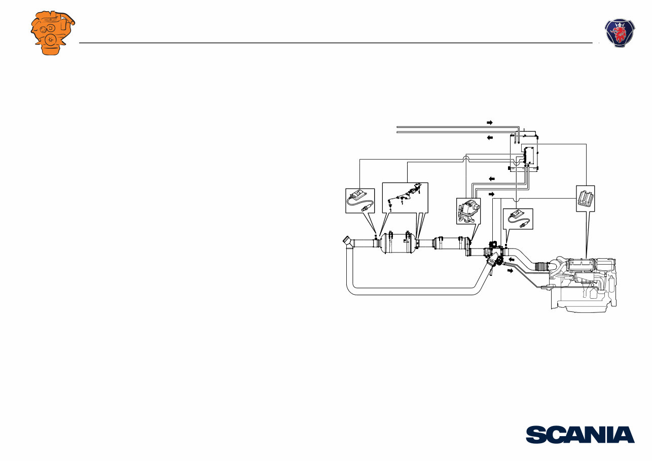
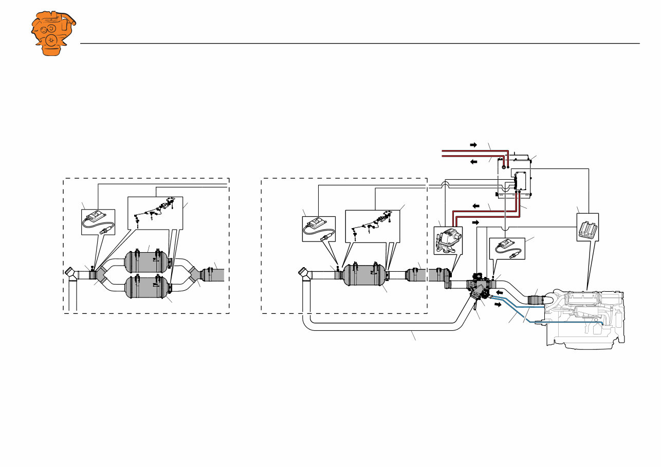
System overview
A B
368 025
1
2
4
3
5
6
7
8
10 9
11
12
13
14
15 15
16
16
17
17
17
18
7
7
18
20
20
19
A: DI16.
B: DI13.
INSTALLATION
MANUAL
© Scania CV AB 2016, Sweden
System overview
02:07 Issue 1.0 en-GB 5
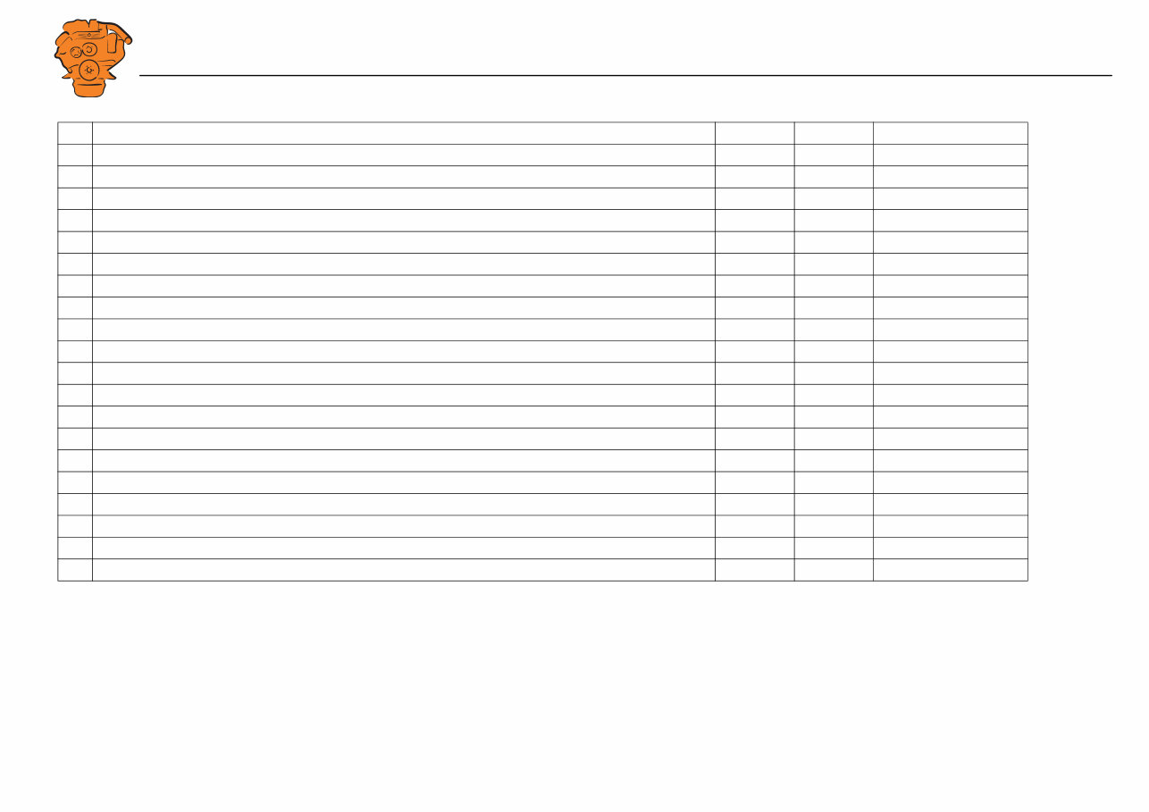
Component Standard Option Fitted by fitter
1. Pressure pipe for reductant from the main tank - - x
2. Return pipe for reductant to the main tank - - x
3. Reductant tank (buffer tank) x - x
4. Pressure pipe for reductant from the buffer tank - - x
5. Return pipe for reductant to buffer tank - - x
6. Engine control unit x - -
7. NOx sensor (x 2) x - x
8. Exhaust bellows - x x
9. Coolant line from the engine to the exhaust control valve actuator - - x
10. Coolant return - - x
11. Pipe section with outlet for NOx sensor T131 x - x
12. Exhaust routing valve with 2 actuators x - x
13. Handle to bypass the SCR system x - -
14. Reductant doser x - -
15. Evaporator x - x
16. Exhaust temperature sensor (x 3) x - x
17. SCR catalytic converter with outlets for 2 exhaust gas temperature sensors x - x
18. Pipe section with outlet for NOx sensor T115 and 1 exhaust gas temperature sensor x - x
19. Bypass pipe - - x
20. Branch pipe (DI16 only) x - x

INSTALLATION
MANUAL
© Scania CV AB 2016, Sweden
Exhaust pipe
02:07 Issue 1.0 en-GB 6
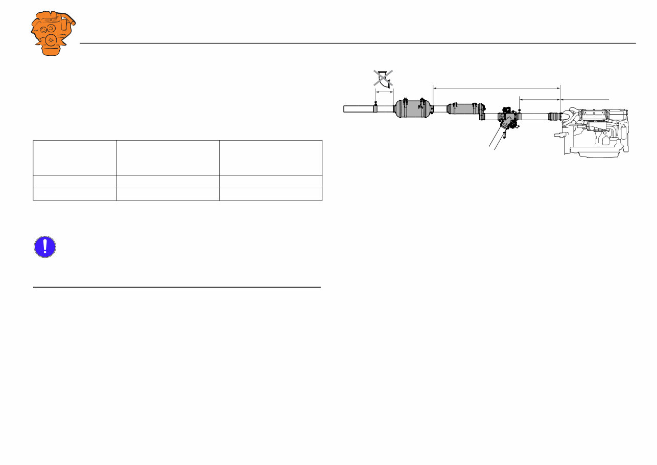
Exhaust pipe
Pipe lengths
From To Max/min pipe length (mm)
A Turbocharger Pipe section for NOx sensor Max 1,500
B Turbocharger Evaporator intake Max 2,000
C Exhaust routing valve outlet Evaporator intake Max 500
D
1
1. DI16 only.
Evaporator outlet Branch pipe Min 300
E Evaporator outlet SCR catalytic converter inlet Max 1,500
F SCR catalytic converter outlet Pipe section for NOx sensor and exhaust temperature sensor Max 400
G Pipe section for NOx sensor and exhaust temperature sensor Exhaust outlet Min 500
1 2
A
B
C E F D G G
E F
368 800
1. DI16.
2. DI13.
INSTALLATION
MANUAL
© Scania CV AB 2016, Sweden
Exhaust pipe
02:07 Issue 1.0 en-GB 7
Exhaust pipe bends
The sum of the exhaust pipe bends between the turbocharger outlet and NOx sensor
upstream of the exhaust routing valve must not exceed 270°.
The sum of the exhaust pipe bends between the turbocharger outlet and SCR catalytic
converter inlet must not exceed 540°. Example:
The radius of the exhaust pipe bends must be at least 1.5 x pipe diameter, based on a
pipe diameter of 127 mm (5 inches).
IMPORTANT!
No exhaust pipe bends may be installed between the SCR catalytic converter outlet
and the NOx sensor downstream of the SCR catalytic converter.
Max. angle before
Number of 90° exhaust
pipe bends
Number of 45° exhaust
pipe bends
SCR catalytic con-
verter
540° 4 off 4 off
540° 6 off 0 off
379 171
Max 540°
Max 270°
Max. number of exhaust pipe bends in the SCR system.
INSTALLATION
MANUAL
© Scania CV AB 2016, Sweden
Exhaust pipe
02:07 Issue 1.0 en-GB 8
Pipe material
The exhaust pipe between the evaporator and the SCR catalytic converter must be
made from stainless metal type 1.4301 or 1.4509, US grade 316L or equivalent. Sca-
nia also recommends that this material is used for other exhaust pipes downstream of
the SCR catalytic converter. Other instructions on exhaust system shape and fitting
are available in 02:04 Exhaust system.
Other requirements
IMPORTANT!
There should always be a flexible connection between the exhaust system and the en-
gine which absorbs the movement of the engine and changes in length in the exhaust
system due to temperature changes. Also see 02:04 Exhaust system.
The brackets for exhaust routing valve, bypass pipe, evaporator and SCR catalytic
converter must be able to bear the weight of the component. The weight of the com-
ponents must not load the exhaust bellows or turbocharger.
Tighten the V-clamps in the SCR system after the engine has warmed up to working
temperature for the first time. Carry out the retightening when the engine has cooled
down again. Tightening torque 20 Nm.
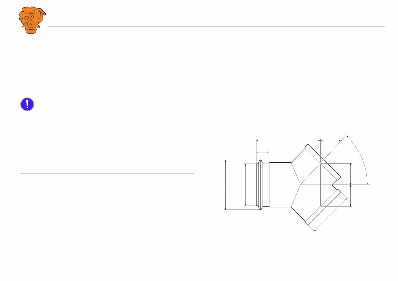
Branch pipe
The image shows the dimensions of the branch pipe used to connect the SCR cata-
lytic converters to DI16.
366 031
2 x
2 x
45°
63,5
40
194
55
Ø122 Ø144
Ø131 x 2
INSTALLATION
MANUAL
© Scania CV AB 2016, Sweden
Main tank for reductant and reductant pipes
02:07 Issue 1.0 en-GB 9
Main tank for reductant and reductant
pipes
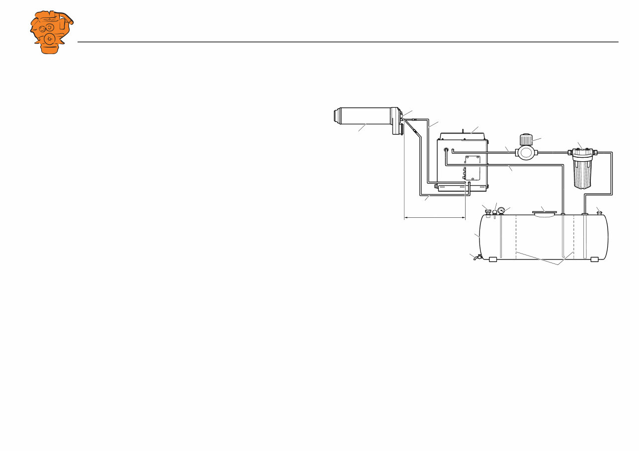
Example of installation
1. Evaporator.
2. Reductant doser.
3. Pressure pipe for reductant from the buffer tank.
4. Return pipe for reductant to buffer tank.
5. Buffer tank.
6. Pressure pipe for reductant from the main tank.
7. Return pipe for reductant to main tank.
8. Feed pump.
9. Prefilter.
10. Main tank for reductant.
11. Filling.
12. Overfill protection.
13. Level gauge.
14. Inspection hatch.
15. Ventilating valve.
16. Draining tap.
17. Baffle plate.
A = Max. height 2 metres from the pressure pipe connection on the buffer tank to the
reductant doser, max. length 16 metres.
1
5
10
16
2
15
6
9 8
7
14
17
11
13
12
3
4
380 406
A
Example of installation of the main tank for reductant and reductant pipes

INSTALLATION
MANUAL
© Scania CV AB 2016, Sweden
Main tank for reductant and reductant pipes
02:07 Issue 1.0 en-GB 10
Materials for pipes and main tank
The main reductant tank, the reductant pipes and all couplings must be made of urea-
resistant material, such as stainless steel X5CrNi 18-10 in accordance with SS-EN
10088-2 or similar. Follow classification society requirements. If the material is
welded, its anti-corrosive qualities must be retained.
Dimension the reductant pipes according to the dimensions of the connections on the
buffer tank, as indicated in the Connecting the reductant tank section.
Main tank
• Dimension the main tank so that there is sufficient reductant for the specific use
and area. Reductant consumption is approx. 9% of fuel consumption.
• The tank must be fitted with internal baffle plate to prevent the reductant from be-
ing thrown about at sea.
• The tank must have a drain tap.
• There must be ventilation or bleed line from the upper part of the tank to the out-
side of the hull. It should be designed so that water cannot enter and so that re-
ductant cannot run out when the ship is leaning heavily.
• The tank must be fitted with inspection hatches so that it can be inspected and
cleaned inside.
• The pipe fitting should be at a sufficient distance from the bottom of the tank, so
as not to suck up deposits gathered at the bottom.
Main tank to buffer tank
• The pipes to the buffer tank should be as short as possible and should be mounted
in such a way that they cannot be exposed to mechanical damage.
• There must be a return pipe from the buffer tank to the main tank so that any sur-
plus fluid runs back to the main tank.
You're Reading a Preview
What's Included?
Fast Download Speeds
Online & Offline Access
Access PDF Contents & Bookmarks
Full Search Facility
Print one or all pages of your manual
$26.99
Viewed 66 Times Today


Secure transaction
What's Included?
Fast Download Speeds
Online & Offline Access
Access PDF Contents & Bookmarks
Full Search Facility
Print one or all pages of your manual
$26.99
This troubleshooting manual serves as a comprehensive guide for troubleshooting the SCR system in a Scania DI13 and DI16 marine engine. It is an invaluable resource for individuals responsible for the maintenance and repair of marine engines. The manual encompasses the essential requirements of an SCR system and provides insights into any modifications implemented since its initial installation.
The manual includes:
- Diagnostics and troubleshooting instructions tailored for the Scania DI13 and DI16 engines
- Comprehensive guidance on repairing or replacing malfunctioning parts
- Detailed explanations of the construction and functionality of the SCR system
- Technical illustrations and diagrams to aid in understanding
- A list of specialized service tools required for the process
This manual contains all the necessary information for effectively troubleshooting the SCR system in a Scania DI13 or DI16 marine engine, catering to both professional mechanics and DIY enthusiasts.


