

Scania DI09, DI13, DI16 Marine engines - Instrumentation 2.0
What's Included?
Fast Download Speeds
Online & Offline Access
Access PDF Contents & Bookmarks
Full Search Facility
Print one or all pages of your manual
03:03 Issue 5.0 en-GB
© Scania CV AB 2016, Sweden
Installation manual
Instrumentation 2.0
Marine engines
DI09, DI13, DI16
344 457
Downloaded from www.Manualslib.com manuals search engine

INSTALLATION
MANUAL
© Scania CV AB 2016, Sweden
03:03 Issue 5.0 en-GB 2
System overview ...................................................................................................... 3
List of abbreviations ............................................................................................ 3
System overview ................................................................................................. 3
Positioning of the displays .................................................................................. 5
Connection ............................................................................................................... 7
Electrical cables................................................................................................... 7
Junction box, connection ..................................................................................... 8
Junction box, components ................................................................................. 11
Main display (DCU), junction blocks ............................................................... 12
Auxiliary display (RP), junction blocks ............................................................ 19
Safety module (SDU), connection .................................................................... 22
Gateway – overview.......................................................................................... 22
Position of the monitors on the engine .............................................................. 23
Connecting emergency stop .............................................................................. 25
Engine shutdown override in systems with safety device unit (SDU) .............. 26
Using the main display .......................................................................................... 27
First start............................................................................................................ 27
Navigation ......................................................................................................... 30
Administration in the main display ................................................................... 33
Configuring and upgrading software with USB memory stick......................... 37
Configuring the main display with a USB memory stick ................................. 38
Upgrading the main display or auxiliary display software ............................... 39
Copying one configuration file in the main display .......................................... 39
Configuring the main display via a web browser ............................................... 40
Connecting a computer to the main display ...................................................... 40
General information about the IP address ......................................................... 42
Homepage.......................................................................................................... 43
Logging in to the main display.......................................................................... 44
Important system settings: dcu / Miscellaneous / System Type........................ 44
Password: dcu > Password................................................................................ 45
File management: dcu > File ............................................................................ 46
Configuring input signals: dcu > I/O Configuration > Config Inputs .............. 47
Configure output signals: dcu > I/O Configuration / Config Outputs .............. 63
Designing instrument pages: dcu > Interface Design ....................................... 67
Set the sequences for starting, stopping and for lubrication: dcu > Start/Stop/Pre-
lube ................................................................................................................... 69
Settings for the user interface: dcu > User Interface ........................................ 72
Changing the engine designation: dcu > Engine Model ................................... 73
Setting the maintenance interval: dcu > Service Interval ................................. 74
Network settings: dcu > Communication ......................................................... 75
Other functions: dcu > Miscellaneous .............................................................. 77
SDU .................................................................................................................. 82
Auxiliary display ................................................................................................... 83
First start ........................................................................................................... 83
Administration in the auxiliary display ............................................................ 85
Examples of connection of sensors and monitors .............................................. 92
Connection of 4-20 mA, e.g. oil pressure sensor for the reverse gear .............. 92
Connection of PT100, e.g. coolant temperature sensor .................................... 94
Connection of switch input, e.g. low engine oil pressure monitor ................... 96
Downloaded from www.Manualslib.com manuals search engine
INSTALLATION
MANUAL
© Scania CV AB 2016, Sweden
System overview
03:03 Issue 5.0 en-GB 3
System overview
List of abbreviations
The abbreviations in the list below are used in this manual. DCU, RP och SDU ap-
pear in the display interface and in the configuration interface.
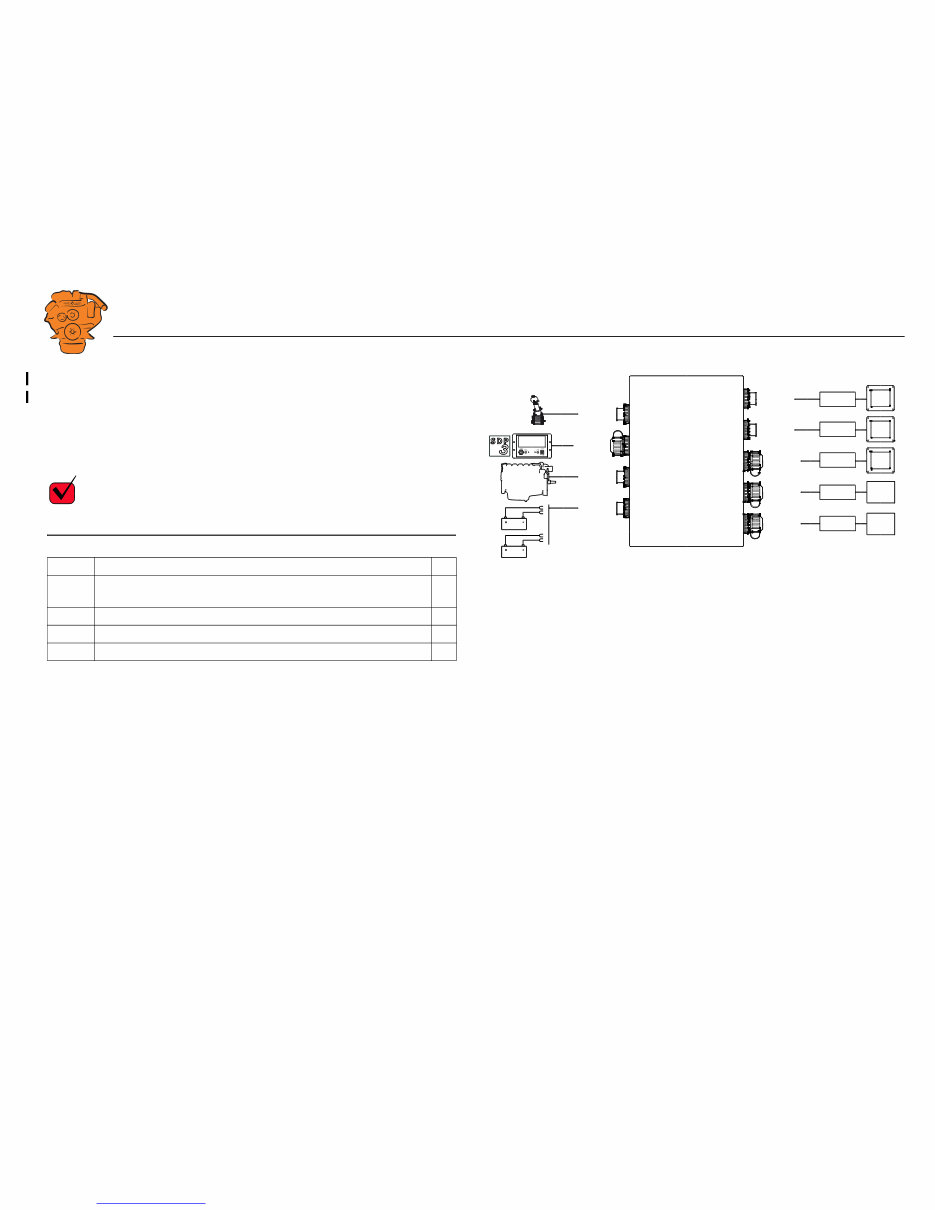
System overview
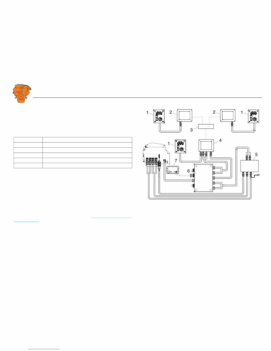
The illustration shows an overview of component parts in a marine engine manage-
ment system prepared for classification.
Main display (DCU)
The main display is the basic unit of the engine management system. Different sensor
values are displayed on the main display touch screen, and different commands are
also carried out there.
The main display is configured using a computer with a web browser via the built in
web server of the main display. This is described in the Configuring the main display
via a web browser section.
Abbreviation Description
DCU Main display
RP Auxiliary display
SDU Safety device unit
FMI Failure Mode Identifier
SPN Suspect Parameter Number
361 900
Example of the layout of a type approved marine engine management system.
1. Control panel.
2. Auxiliary display (RP).
3. Network switch.
4. Main display (DCU).
5. Safety module (SDU).
6. Junction box.
7. Gateway.
Downloaded from www.Manualslib.com manuals search engine
INSTALLATION
MANUAL
© Scania CV AB 2016, Sweden
System overview
03:03 Issue 5.0 en-GB 4
Auxiliary display (RP)
The auxiliary display is an option and has the same user interface as the main display.
The auxiliary display reads the configuration from the main display. This makes it
easy to retrofit.
Control panel
The engine can be started and stopped through the control panel. It can also be used
to activate and adjust engine speed settings 1 or 2. The engine installation can be car-
ried out with or without a control panel.
Network switch
A network switch is only required if more than one auxiliary display is connected to
the engine management system. If the system only contains one auxiliary display, it
is connected directly to the main display via a crossover network cable.
Safety module (SDU)
The safety device unit has monitoring and shutdown functions and is a requirement
for classified engine management systems. It should be easily accessible so that
alarms can be acknowledged in an easy way.
Junction box
The junction box is used to connect all the parts of the engine management system to
the engine. The junction box also contains fuses. It should be easily accessible.
Gateway
The gateway reads specific messages about position and speed via NMEA 2000, so
that the instrumentation can calculate fuel consumption per nautical mile. The gate-
way cannot process messages other than these. The gateway requires software ver-
sion 2.11 or later to be installed in the displays.
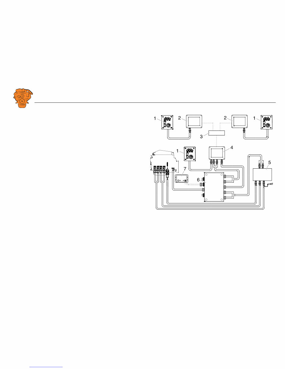
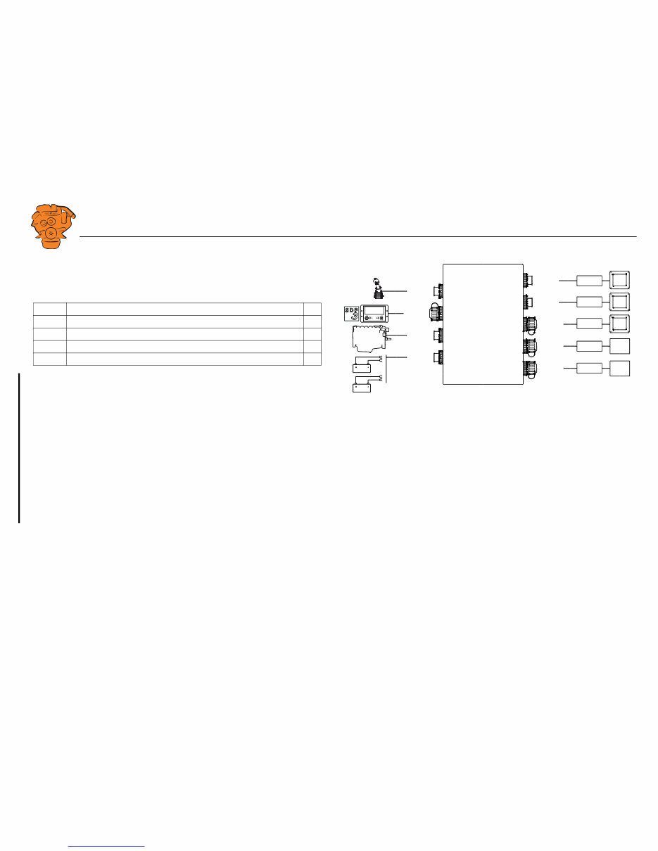
361 900
Example of the layout of a type approved marine engine management system.
1. Control panel.
2. Auxiliary display (RP).
3. Network switch.
4. Main display (DCU).
5. Safety module (SDU).
6. Junction box.
7. Gateway.
Downloaded from www.Manualslib.com manuals search engine
INSTALLATION
MANUAL
© Scania CV AB 2016, Sweden
System overview
03:03 Issue 5.0 en-GB 5
Positioning of the displays
Do not position the displays so that they are exposed to direct sunlight. This impairs
the readability of the displays. The user should have full access to the displays. It
must also be easy to access the connections on the rear of the displays.
IMPORTANT!
The displays must not be fitted on vibrating equipment. They may only be positioned
next to the engine bed if either the engine or the display housing has vibration damp-
ing.
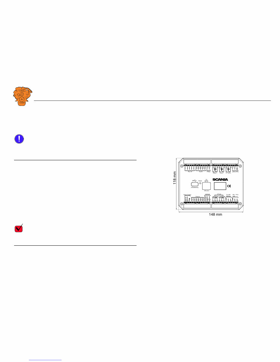
Installation dimensions
Provide a 150 x 120 mm rectangle where the display is to be positioned. There must
be at least 70 mm free space behind the display.
Main display
Scania recommends positioning the main display in the engine compartment for the
following reasons:
• To ensure that operation and monitoring are close to the engine.
• To minimise the lengths of the electrical cables between the sensors and main dis-
play.
• To reduce the risk of electrical interference caused by long electrical cables.
REQUIREMENT!
On a type approved installation, the main display must be located in the engine com-
partment.
361 901
Installation dimensions for the main display and auxiliary display.
Downloaded from www.Manualslib.com manuals search engine

INSTALLATION
MANUAL
© Scania CV AB 2016, Sweden
System overview
03:03 Issue 5.0 en-GB 6
Auxiliary display
The auxiliary display is normally positioned outside the engine compartment, but can
also be positioned in the engine compartment.
Downloaded from www.Manualslib.com manuals search engine

INSTALLATION
MANUAL
© Scania CV AB 2016, Sweden
Connection
03:03 Issue 5.0 en-GB 7
Connection
Electrical cables
To protect against electromagnetic interference, Scania recommends that all electri-
cal cables within the system are twisted in pairs with 35-40 turns/m. This only applies
to external signal cables connected to the system.
IMPORTANT!
If a shielded electrical cable is used, the shielding should be connected to ground, not
to 0 V. Only connect the shielding to one end of the electrical cable.
To provide good separation of the electromagnetic interference that can occur, some
of the electrical cables can be routed separately from the others, e.g. the signal cable
from a magnetic pulse sensor.
Electrical cables for electric power supply must have a minimum cross section of
2.5 mm
2
.
Ground
IMPORTANT!
Separate ground and 0 V. In marine installations, ground and 0 V must not be con-
nected. The hull is ground and the battery negative terminal is 0 V.
24 V and 0 V are filtered in the main display in order to reduce electromagnetic in-
terference. If ground and 0 V are connected together, the filters in the main display
will not function.
Downloaded from www.Manualslib.com manuals search engine

INSTALLATION
MANUAL
© Scania CV AB 2016, Sweden
Connection
03:03 Issue 5.0 en-GB 8
Junction box, connection
Minimum connection
The minimum connection required for the system to function is for the pins on con-
nector C4066 to be connected. If the throttle control is to be controlled via the main
display, then pins 1 and 2 of connector C4068 must also be connected.
Please refer to the electrical system installation manual 03:01 for information on how
to connect the throttle control to the engine control unit. If the throttle control is con-
nected to the engine control unit, secondary throttle control cannot be used.
C4066
Connection of power supply to the engine management system and instrumentation
2.0 (battery).
Note:
If the system has a safety device unit (SDU), 2 separate groups of batteries must be
used.
Pin Description I/O
1 30 voltage, 24 V -
2 Ground (battery negative terminal) -
3 30 voltage, 24 V -
4 Ground (extra battery negative terminal) -
1
2
3
4
DCU
DCU
DCU
SDU
SDU
C4068
C4067
C4052
C4053
C4056
C4058
C4059
C4054
C4055
C4057
C4060
C4061
C4062
C4066
Gat eway
C4001
372 773
Connecting the junction box.
Downloaded from www.Manualslib.com manuals search engine
INSTALLATION
MANUAL
© Scania CV AB 2016, Sweden
Connection
03:03 Issue 5.0 en-GB 9
C4062
Connection to engine connector C4001.
C4067
Diagnostic socket for connecting e.g. SDP3 and CAN communication. Use connec-
tor 1 508 055 and hand crimping tool 99 494.
REQUIREMENT!
Any equipment connected to the connector must comply with the CAN specification.
Pin Description I/O
1 15 voltage: 24 V after fuse F4005 and relay in the junction box. Con-
trolled by the system being active.
-
2 Ground -
3 CAN high -
4 CAN low -
1
2
3
4
DCU
DCU
DCU
SDU
SDU
C4068
C4067
C4052
C4053
C4056
C4058
C4059
C4054
C4055
C4057
C4060
C4061
C4062
C4066
Gat eway
C4001
372 773
Connecting the junction box.
Downloaded from www.Manualslib.com manuals search engine
INSTALLATION
MANUAL
© Scania CV AB 2016, Sweden
Connection
03:03 Issue 5.0 en-GB 10
C4068
Connecting the incoming throttle actuation signal. The update frequency is 100 Hz,
with a median filter on 3 readings.
C4052
Connection to main display via C4054.
C4053
Connection to main display via C4055.
C4056
Connection to main display via C4057.
C4058
Connection to safety device unit (SDU) via C4060.
C4059
Connection to safety device unit (SDU) via C4061.
Pin Description I/O
1 24 V (0.2 A), voltage supply to passive throttle control O
2 Input for signal from throttle control, 4-20 mA I
3 Not used -
4 Not used -
1
2
3
4
DCU
DCU
DCU
SDU
SDU
C4068
C4067
C4052
C4053
C4056
C4058
C4059
C4054
C4055
C4057
C4060
C4061
C4062
C4066
Gat eway
C4001
372 773
Connecting the junction box.
Downloaded from www.Manualslib.com manuals search engine
You're Reading a Preview
What's Included?
Fast Download Speeds
Online & Offline Access
Access PDF Contents & Bookmarks
Full Search Facility
Print one or all pages of your manual
$26.99
Viewed 65 Times Today


Secure transaction
What's Included?
Fast Download Speeds
Online & Offline Access
Access PDF Contents & Bookmarks
Full Search Facility
Print one or all pages of your manual
$26.99
- This Parts Manual covers all the models of Scania DI09, DI13, and DI16 Marine engines for Instrumentation 2.0. It is an essential reference guide for servicing, maintenance, repairs, troubleshooting, and diagnostics.
- The manual contains detailed drawings and schematics to help identify various components of these engines. It includes all parts names and numbers, contents, and navigation instructions for every model listed.
- Written in English, the manual comprises 140 printable and searchable pages. It can be accessed with smart devices such as laptops, PCs, etc., providing convenience and flexibility.
- Additionally, it includes frequent reference charts, technical data, and clear instructions for easy understanding, helping users save time, money, and effort by providing all necessary information.
- With this Parts Manual, both professional mechanics and DIY enthusiasts can identify and order the correct part for their engine model, ensuring peak performance and reliability.


