INSTALLATION
MANUAL
©
Scania CV AB 2015, Sweden
03:01 Issue 5.0 en-GB 1
Electrical system
Industrial engines
DC09, DC13, DC16
Marine engines
DI09, DI13, DI16
INSTALLATION
MANUAL
©
Scania CV AB 2015, Sweden
03:01 Issue 5.0 en-GB 2
Introduction ............................................................................................................. 3
Different requirements ........................................................................................ 3
Grounding ............................................................................................................ 3
Abbreviations ...................................................................................................... 3
Safety during electric welding ............................................................................. 3
Batteries and alternators ........................................................................................ 4
Batteries ............................................................................................................... 4
Battery cables ...................................................................................................... 5
Connection of batteries ........................................................................................ 6
Battery master switch .......................................................................................... 7
Alternator charging for marine engines .............................................................. 8
Marine engines with split ground system ............................................................ 9
Electrical cables ..................................................................................................... 10
Routing cables ................................................................................................... 10
Calculating cable cross-section ......................................................................... 11
Splicing and repair ............................................................................................ 14
Connection to engine ............................................................................................. 16
Connection to engine without Scania base system ............................................ 16
Current consumption of the electrical system ................................................... 17
Engine interface ................................................................................................. 18
Pin numbering for connectors ........................................................................... 21
Connection of starter motor or alternator .......................................................... 25
Connection of coolant level monitor ................................................................. 26
Connection of oil level sensor ........................................................................... 30
Connection of water separating prefilter on marine engines (PDE engines) .... 32
Engine control unit ................................................................................................ 33
Operating voltage .............................................................................................. 33
Protection class .................................................................................................. 33
Connection of limp home mode ........................................................................ 34
Engine running signal ....................................................................................... 36
Work description for connectors ......................................................................... 37
Connector for engine interface ......................................................................... 37
Connector for engine control unit ..................................................................... 40
INSTALLATION
MANUAL
©
Scania CV AB 2015, Sweden
Introduction
03:01 Issue 5.0 en-GB 3
Introduction
Different requirements
S6 engine control units are used for PDE engines. S8 engine control units are used
for XPI engines.
There are two different requirements for the electrical installation of S6 and S8: with
or without Scania's base system. This installation manual does not describe Scania's
electrical system. Information about the electrical systems can be found in
• 03:02 Coordinator and base system,
• 03:03 Instrumentation 2.0.
Grounding
In this document the term ground is used. Ground means that there is a connection to
the battery negative terminal (U31).
Abbreviations
Abbreviations used in this document are listed in the table below.
Abbreviation Explanation
EGR Emission control system (Exhaust Gas Recirculation)
PDE Fuel injection system (unit injector)
S6 Engine control unit for PDE engines
S8 Engine control unit for XPI engines
SCR Emission control system (Selective Catalytic Reduction)
SDP3 Scania Diagnos & Programmer 3
XPI Fuel injection system (extra high pressure injection)
Abbreviations for voltage
The abbreviations in the table below are used to describe different types of voltage.
Unless otherwise specified, always +24 V.
Safety during electric welding
IMPORTANT!
When carrying out welding work on and near the engine, disconnect the battery and
alternator leads. Pull out the multi-pin connector for the engine control unit as well.
Connect the welding clamp as close to the welding site on the component as possible.
The welding clamp must not be connected to the engine, or so that the current can
cross a bearing.
When welding is finished:
1. Connect the alternator and engine control unit cables first.
2. Then connect the batteries.
Abbreviation Explanation
U15 Starter key voltage (15 voltage)
U30 Battery voltage
INSTALLATION
MANUAL
©
Scania CV AB 2015, Sweden
Batteries and alternators
03:01 Issue 5.0 en-GB 4
Batteries and alternators
Batteries
Use lead batteries of the starter battery type. This type of battery is able to deliver
high current even at low temperatures for long enough for the engine to start.
Connect two 12 V batteries in series for 24 V system voltage.
If standard lead acid batteries are used, Scania recommends batteries with a starting
capacity of min. 160 Ah and a cold cranking amperage of 800 A for all engine types.
In warm climates in which the temperature only briefly falls below 0°C, batteries
with a starting capacity of min. 118 Ah and a cold cranking amperage of 490 A at
0°C may be used for all engine types.
The battery capacity indicates how high a current a battery can be discharged at for
20 hours at ambient temperature. A 100 Ah battery can, for example, be discharged
at max. 5 A for 20 hours.
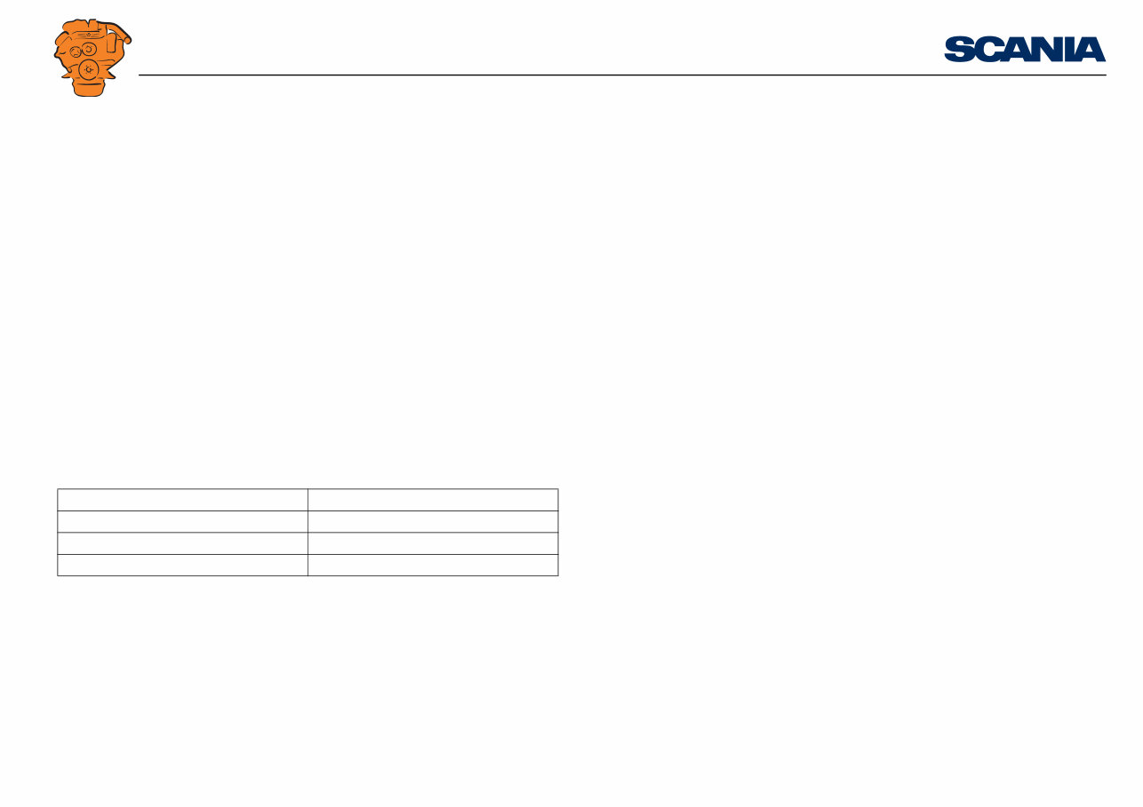
At low temperatures, the battery capacity is reduced considerably as shown in the fol-
lowing table:
The cold cranking amperage above indicates the highest current with which a 12 V
battery can be loaded at -18°C so that the terminal voltage after 30 seconds is a min-
imum of 8.4 V and the discharge time to 6 V is no less than 120 seconds.
Battery capacity at +20°C Battery capacity at -18 °C
100% 50%
70% 35%
40% 25%
INSTALLATION
MANUAL
©
Scania CV AB 2015, Sweden
Batteries and alternators
03:01 Issue 5.0 en-GB 5
Note:
If the engine is fitted with an alternator, the battery master switch must not be
switched off or the batteries disconnected when the engine is running. Voltage peaks
can damage components in the alternator and the charge regulator.
The batteries in stand-by generator sets must be checked for their state of charge and
fluid level and charged if required. Batteries may be charged either during the normal
test drive (once a month) for approx. 1 hour or using a battery charger and timer.
Boost charge and continuous trickle charge shorten the service life of the batteries.
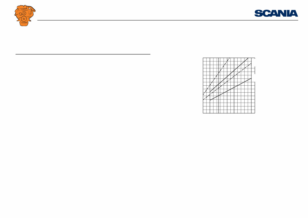
Battery cables
When manufacturing battery cables, dimension the cables between the battery and
starter motor as depicted in the diagram. This indicates the minimum permissible ca-
ble cross-section at different lengths for the various engine types.
The cable length in the diagram relates to the total length of both positive and nega-
tive cables.
Minimum permissible cable cross-section is 70 mm
2
. If the ambient temperature con-
stantly exceeds +10°C, the minimum permissible cable cross-section is 50 mm
2
.
50
1
2
3
4
5
10
15
70 95 120 140 190
9 Y
X
9
13
16
13
16
343 117
Diagram for dimensioning of battery cables
The dotted lines apply at a constant ambient temperature of more than 10°C.
The unbroken lines apply at an ambient temperature of -20°C.
Y = Total cable length in metres
X = Cable cross-section in mm²
INSTALLATION
MANUAL
©
Scania CV AB 2015, Sweden
Batteries and alternators
03:01 Issue 5.0 en-GB 6
Connection of batteries
Connect the battery cables correctly, i.e. negative (-) to the engine ground point and
positive (+) to the starter motor terminal screw 30.
Note:
The alternator rectifier diodes will be damaged if these cables are connected incor-
rectly.
Do not disconnect the connections while the engine is running, as this may damage
the charge regulator.
• Removing: Always disconnect the negative cable before the positive cable.
• Fitting: Always connect the positive cable before the negative cable to reduce the
risk of short-circuiting the battery with the tool.
• Make sure that the battery box, batteries and battery cable terminals are clean.
• Do not bang the battery cable terminals. Terminal posts and cell plates come off
easily.
• Lubricate battery cable terminals and terminal posts using a thin layer of Vaseline
or grease.
INSTALLATION
MANUAL
©
Scania CV AB 2015, Sweden
Batteries and alternators
03:01 Issue 5.0 en-GB 7
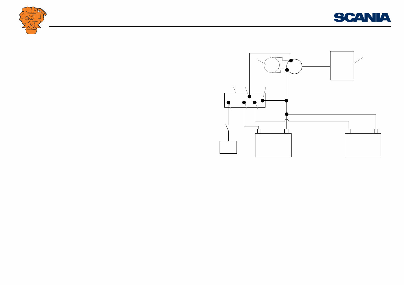
Battery master switch
If a battery master switch is installed between the starter motor and the batteries, it
must be positioned as close to the batteries as possible.
The power must not be switched off directly after switching off the engine. In order
for the control units to store operational data and switch off any systems, it is impor-
tant to allow a 10 second delay before switching off the power.
IMPORTANT!
The SCR system may need up to 30 minutes to cool the reductant doser in extreme
conditions. The battery master switch must not be switched off before then.
Status for post-running is sent out in CAN message DLN7. More information is
available in the CAN interface installation manual.
P1
S6
M1
M
30
50
31
B+
B-
W
D+
+
+ -
-
G
P3
335 784
Mechanical battery master switch
M1 = Starter motor
P1 = Battery
P3 = Alternator 1
S6 = Mechanical battery master switch
INSTALLATION
MANUAL
©
Scania CV AB 2015, Sweden
Batteries and alternators
03:01 Issue 5.0 en-GB 8
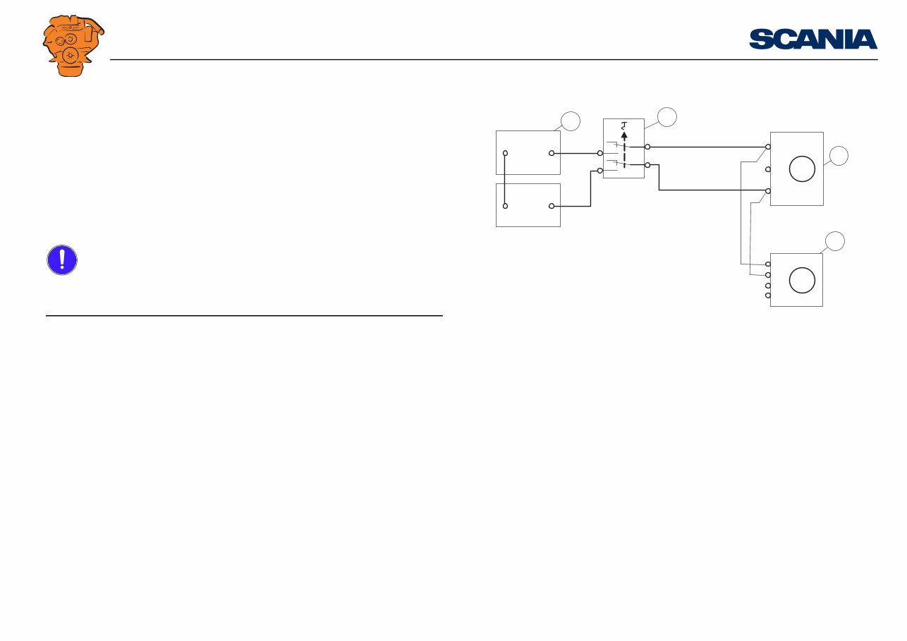
Alternator charging for marine engines
In order for the alternator to start charging, the B+ terminal of the alternator must
have +24 V. For certain engine installations, it may be necessary to use an electronic
battery insulator in order for B+ to receive +24 V. Refer to the illustration for con-
nection of the battery insulator.
1. Engine control unit
2. Alternator 2 (only with double alternators)
3. Battery insulator
4. Input to battery insulator
5. Ground
6. Output from battery insulator
7. Output from battery insulator
8. 15 voltage to battery insulator
331 675
B-
+ -
ECU G
+ -
15
G
B+ 1
2
3 4 5
8 7 6
INSTALLATION
MANUAL
©
Scania CV AB 2015, Sweden
Batteries and alternators
03:01 Issue 5.0 en-GB 9
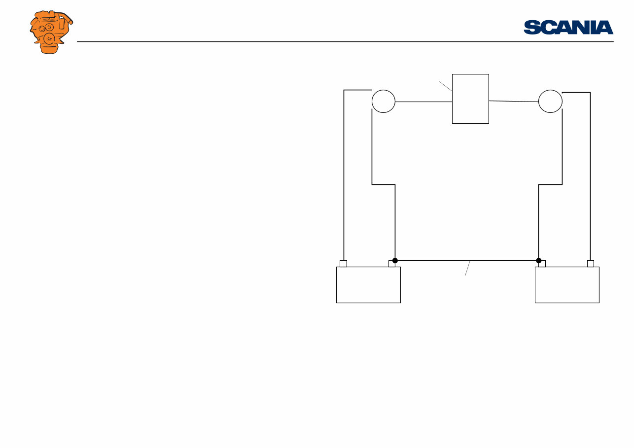
Marine engines with split ground system
When double alternators controlled from the engine control unit charge different bat-
tery groups, the battery negative terminals must be connected together, otherwise a
fault code is generated.
1. Engine control unit
2. Ground connection between batteries
ECU
+ - - +
B+
B+
B-
G
B-
G
331 674
1
2
INSTALLATION
MANUAL
©
Scania CV AB 2015, Sweden
Electrical cables
03:01 Issue 5.0 en-GB 10
Electrical cables
Routing cables
When engines are supplied without instrumentation, all cables from the engine, ex-
cept for the starter and alternator cables, should be collected together on a junction
block or in a junction box and then continued with an extension cable to the instru-
ment panel or central electric unit.
Do not place the junction box or junction block directly on the engine as this will ex-
pose it to harmful vibrations. Protect it from water, oil, heat and mechanical damage.
Ideally, route the cables along the bottom part of the engine where there is least
movement.
When routing electrical cables, there must be no risk of chafing. Use chafing covers
if there is such a risk. The cables must not touch any sharp edges, radius < 0.5 mm,
e.g. sharp edges or ends of threaded screws.
When the cables are clamped to rubber hoses, the cable must not interfere with the
movement of the hose.
The cables must be long enough so that they are not stretched.
The distance between the cable clamps, e.g. cable ties, should be 350-400 mm.
The cables must be routed as far away from hot areas, > 70°C, as possible. The fol-
lowing minimum distance applies if there is no heat shield:
• Exhaust pipe upstream of silencer, front part of silencer – 100 mm.
• Exhaust pipe downstream of silencer, rear part of silencer – 60 mm.
• Exhaust pipe, engine and cab heater – 40 mm.
• Coolant pipe, engine – 60 mm.
A conventional cable harness and CAN cable harness can be routed side by side with-
out interference.
You're Reading a Preview
What's Included?
Lifetime Access
Access PDF Contents & Bookmarks
Print one or all pages of your manual