01:07 Issue 17 en-GB
© Scania CV AB 2018, Sweden
Installation manual
Exhaust gas aftertreatment
Industrial engines
DC09, DC13, DC16
399 091
INSTALLATION
MANUAL
© Scania CV AB 2018, Sweden
01:07 Issue 17 en-GB 2
Changes from the previous issue ............................................................................ 3
SCR and reductant .................................................................................................. 3
Vibration limits ................................................................................................... 3
System overview – Stage V ..................................................................................... 4
System overview of mechanics ........................................................................... 4
System overview of electrics ............................................................................... 5
Exhaust pipe ........................................................................................................ 6
Components – Stage V ............................................................................................ 9
Particulate filter unit ............................................................................................ 9
Differential pressure sensor ............................................................................... 12
SCR unit ............................................................................................................ 14
Exhaust gas temperature sensor ........................................................................ 18
NOx sensor ........................................................................................................ 18
System overview – Stage IV/Tier 4f and Stage III B/Tier 4i ............................. 20
System overview of mechanics ......................................................................... 20
System overview of electrics ............................................................................. 21
Exhaust pipe ...................................................................................................... 22
Components – Stage IV/Tier 4f and Stage III B/Tier 4i .................................... 25
Oxidation catalytic converter ............................................................................ 25
Evaporator ......................................................................................................... 26
Hydrolysis catalytic converter ........................................................................... 29
SCR catalytic converter ..................................................................................... 31
Exhaust gas temperature sensor ........................................................................ 32
NOx sensor ........................................................................................................ 32
Reductant tank ...................................................................................................... 35
Tank volumes .................................................................................................... 36
Dimensions ........................................................................................................ 37
Position ............................................................................................................. 39
Mounting ........................................................................................................... 41
Connecting the reductant tank .......................................................................... 44
Ventilation ........................................................................................................ 48
Available lengths of reductant hoses ................................................................ 49
Coolant connections on the engine ................................................................... 50
Warnings and torque reduction for Stage V ...................................................... 51
Reaction at low reductant level ......................................................................... 52
Reaction to faults in the exhaust gas aftertreatment system . ............................ 53
Regeneration of the particulate filter ................................................................ 54
Warnings and torque reduction for Stage IIIB/IV/Tier 4i/Tier 4f ................... 55
Reaction at low reductant level ......................................................................... 55
Reaction to fault in SCR system ....................................................................... 56
Periodic hydrocarbon evaporation for Stage IV/V/Tier 4f engines ................. 57
Engines without exhaust brake ......................................................................... 58
Engines with exhaust brake .............................................................................. 58
Important data ...................................................................................................... 59
INSTALLATION
MANUAL
© Scania CV AB 2018, Sweden
Changes from the previous issue
01:07 Issue 17 en-GB 3
Changes from the previous issue
The changes made in this document compared with the previous issue are marked
with a line in the left-hand margin. The changes are also described below.
• Information about Stage V engines has been added.
• The illustration in section Drain hole for the reductant tank has been corrected.
• The illustration in section Connection of reductant doser for Stage IV/Tier 4f and
Stage III B/Tier 4i has been corrected.
SCR and reductant
SCR (Selective Catalytic Reduction) is a system in which reductant is added to the
exhaust gases in order to reduce the nitrogen oxide (NO
x
) content. This document de-
scribes SCR system components and how they should be connected.
Reductant is a solution consisting of urea and water, and is usually called AdBlue®,
DEF, ARLA 32 eller AUS 32, depending on the market. If the engine is equipped
with an SCR system, the reductant is added to the exhaust gases upstream of the cat-
alytic converter. This reduces nitrogen oxide emissions.
Reductant in accordance with ISO 22241 contains 32.5% by weight of urea and
freezes at approximately -11°C (12°F). When the solution freezes, ice and urea al-
ways maintain the same concentration. Always store reductant at a temperature be-
tween -11°C and 30°C (12-86°F).
IMPORTANT!
In order for the emission control to meet the emission requirements set by the public
authorities, the reductant should be specified in accordance with ISO 22241.
IMPORTANT!
Cleanliness is very important when working on the reductant circuit. Clean thorough-
ly around all parts to prevent dirt from entering the system.
When working on the SCR system, the reductant connections may only be lubricated
with soapy water or with distilled water with a 3% urea mixture. Any other types of
lubricants may block and damage the components in the SCR system.
Reductant is highly corrosive. For this reason, only pipes and couplings resistant to
urea may be used in the SCR system. Always rinse away reductant spillage on con-
nections and other parts with lukewarm water to prevent corrosion. If reductant seeps
into electrical connections or electrical cables, these must be renewed.
Vibration limits
The components in the SCR system, including the oxidation catalytic converter,
evaporator, hydrolysis catalytic converter, SCR catalytic converter and reductant
tank, may not be exposed to vibration levels above 3.0 g in the frequency range 8-
500 Hz, if they are not engine-mounted.
The installation contractor must install the SCR components in such a way that they
are exposed to as little vibration from the surroundings as possible. This applies to
e.g. vibrations caused by the firing order, timing gear or road. Resonant frequencies
under 300 Hz must be avoided. Scania refers to ISO standard 16750 for more infor-
mation on vibrations.
Rec. % by weight of urea Limit values according to ISO 22241
32.5% 31.8-33.2%
INSTALLATION
MANUAL
© Scania CV AB 2018, Sweden
System overview – Stage V
01:07 Issue 17 en-GB 4
System overview – Stage V
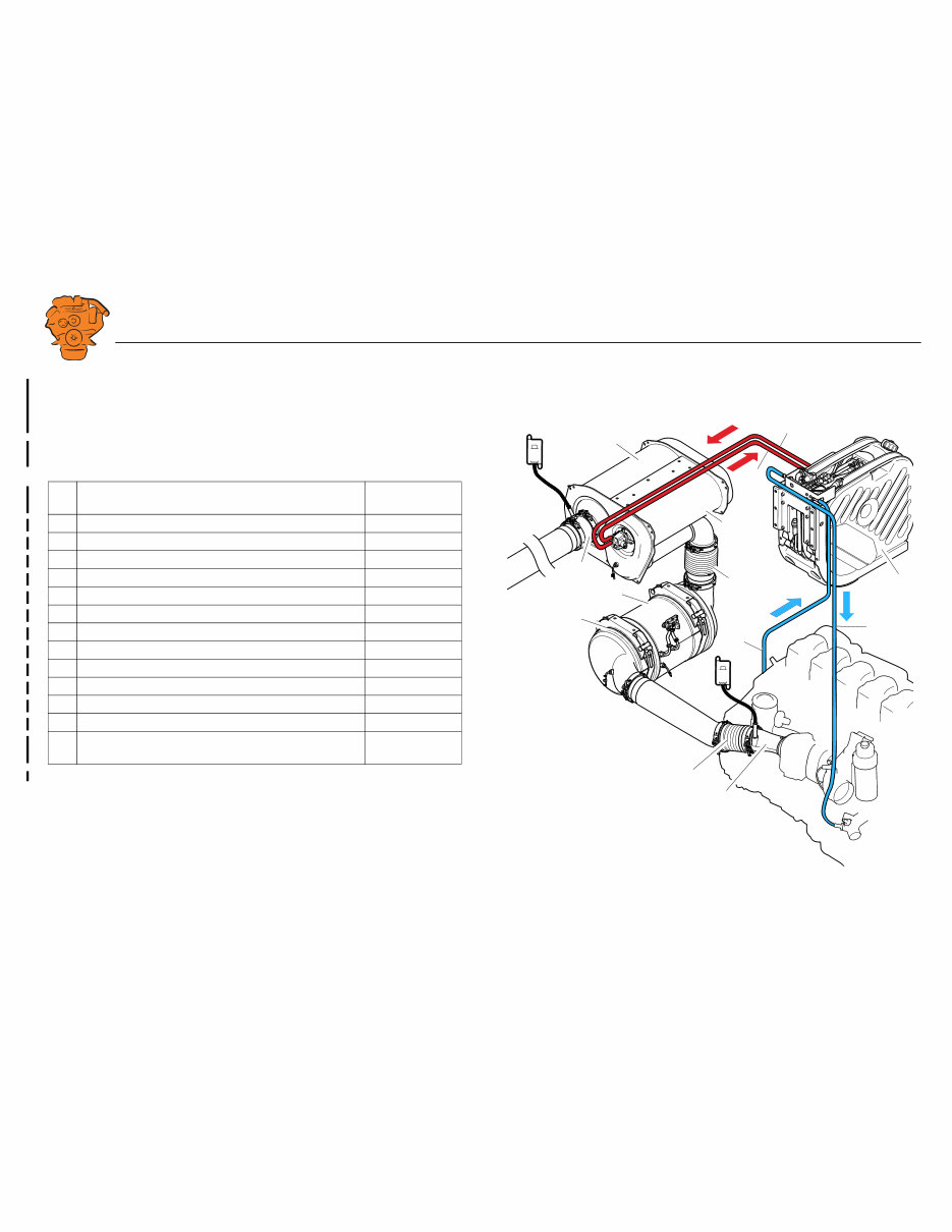
System overview of mechanics
X = the component is always supplied from the factory. O = the component may be
supplied from the factory as an option.
Component Supplied from
the factory
1. Exhaust pipe bend with connection for NO
x
sensor T131. X
1
1. 90° exhaust pipe bend and exhaust brake is available as an option.
2. Exhaust bellows. O
3. Oxidation catalytic converter. X
4. Particulate filter. X
5. Exhaust bellows. O
6. Evaporator. X
7. SCR catalytic converter. X
8. Adapter with connection for NO
x
sensor T115 X
9. Pressure hose for reductant. X
10. Reductant return hose. X
11. Reductant tank. X
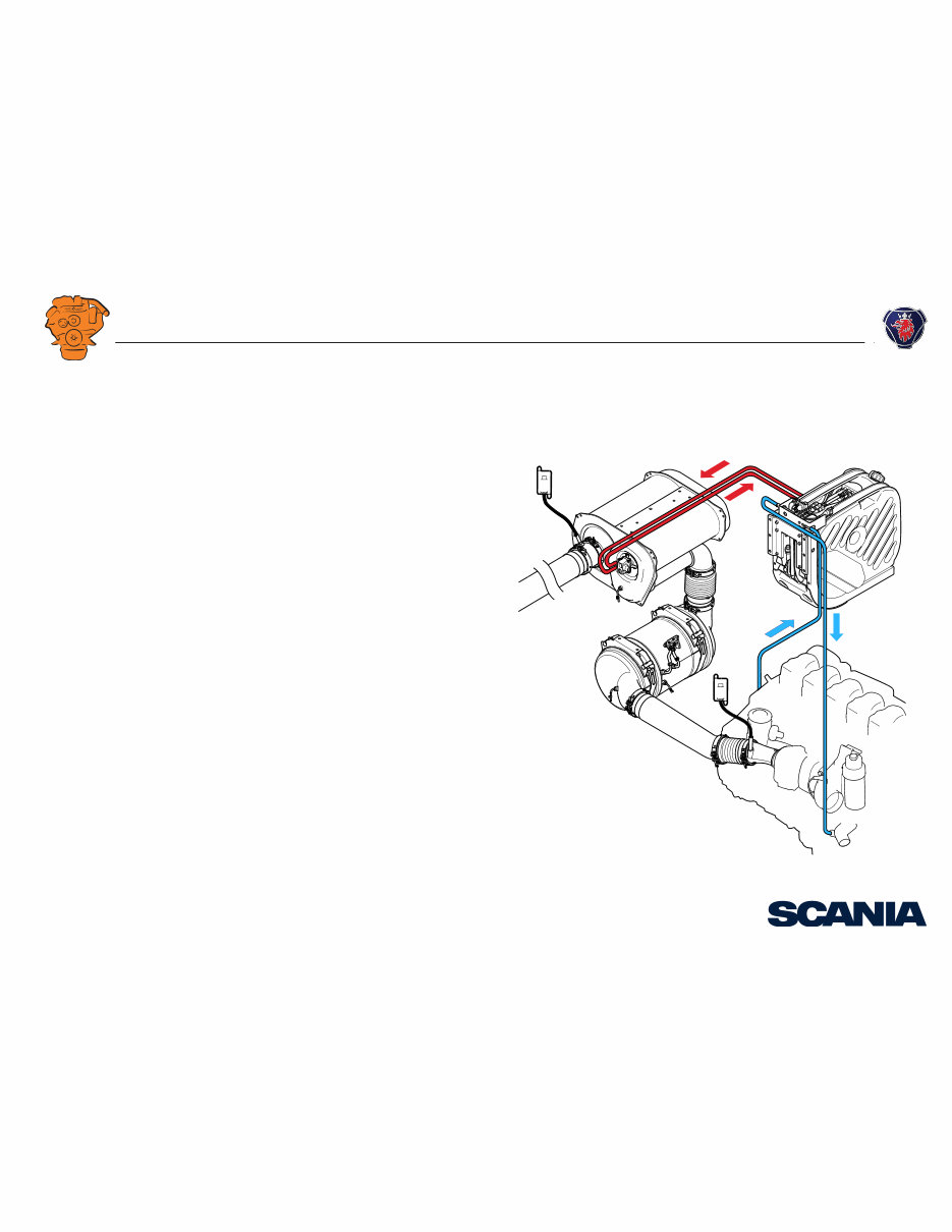
12. Coolant hose for heating the reductant tank and pump. -
13. Coolant hose, return from heating the reductant tank and
reductant pump.
-
2
3
4
5
6
7
9
10
13
11
12
1
8
397 337
INSTALLATION
MANUAL
© Scania CV AB 2018, Sweden
System overview – Stage V
01:07 Issue 17 en-GB 5
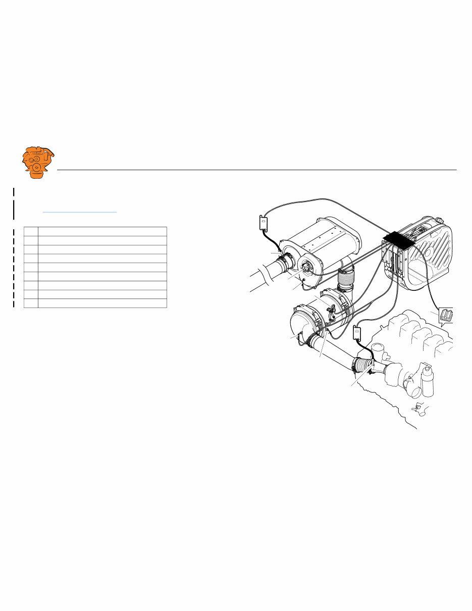
System overview of electrics
Connection of harness-to-harness connectors on the reductant tank is described in
section Connecting the reductant tank . Connection to the engine control unit is de-
scribed in 03:01 Electrical system .
Component
1. NO
x
sensor T131 with control unit.
2. Exhaust gas temperature sensor T4012.
3. Exhaust gas temperature sensor T4010.
4. Differential pressure sensor T141.
5. Exhaust gas temperature sensor T113.
6. Reductant doser V117.
7. NO
x
sensor T115 with control unit.
8. Engine control unit.
3
4
7
8
5
2
1
6
400 242
INSTALLATION
MANUAL
© Scania CV AB 2018, Sweden
System overview – Stage V
01:07 Issue 17 en-GB 6
Exhaust pipe
Pipe lengths
The exhaust gas temperature may drop excessively in the system if the total length
between the NO
x
sensor adapter outlet and the evaporator inlet exceeds 2,700 mm.
There is then a great risk that the engine will go into heating mode, which can in-
crease fuel consumption. The maximum permitted exhaust gas temperature reduc-
tion is indicated in 01:04 Exhaust system .
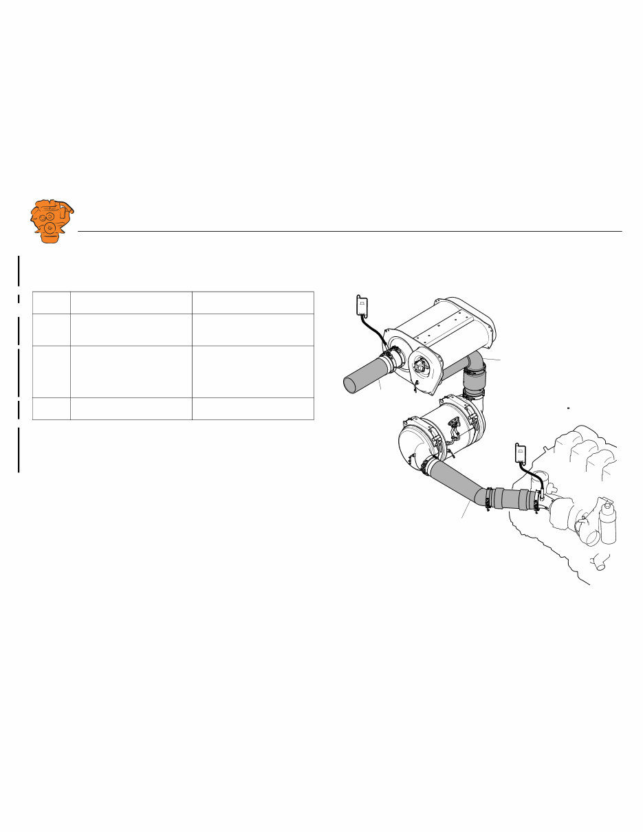
Pipe sec-
tion
Description Pipe length (mm)
A From the adapter for NO
x
sensor
T131 to the oxidation catalytic
converter inlet.
Max. 1,700.
A+B Total length from the adapter for
NO
x
sensor T131 to the evaporator
intake, excluding the particulate
filter unit (oxidation catalytic con-
verter and particulate filter).
Max. 2,700.
C From the adapter for NO
x
sensor
T115 to the exhaust outlet.
At least 500 mm.
A
B
C
397 339
INSTALLATION
MANUAL
© Scania CV AB 2018, Sweden
System overview – Stage V
01:07 Issue 17 en-GB 7
Note:
The requirement for pipe length D applies only if a 90° pipe bend is connected di-
rectly downstream of the SCR unit.
Pipe sec-
tion
Description Pipe length (mm)
D Straight pipe section up-
stream of the adapter for
NO
x
sensor T115.
At least 200 mm.
D
C
399 087
INSTALLATION
MANUAL
© Scania CV AB 2018, Sweden
System overview – Stage V
01:07 Issue 17 en-GB 8
Pipe material
Scania recommends that the exhaust pipe between the particulate filter unit and SCR
unit be made from stainless metal type 1.4301 or 1.4509, US grade 316L or equiva-
lent.
Other instructions on exhaust system shape and fitting are available in 01:04 Exhaust
system .
Other requirements
There must always be a flexible connection between the turbocharger and particulate
filter unit. Scania also recommends a flexible connection between the particulate fil-
ter unit and SCR unit due to tolerances and heat expansion. Also see 01:04 Exhaust
system .
Tightening torque for V-clamps
The tightening torque for all V-clamps in the exhaust gas aftertreatment system is
20 Nm.
IMPORTANT!
Scania recommends that the V-clamps in the exhaust gas aftertreatment system be
retightened when the engine has reached the operating temperature for the first time.
Carry out the retightening when the engine has cooled down again.
INSTALLATION
MANUAL
© Scania CV AB 2018, Sweden
Components – Stage V
01:07 Issue 17 en-GB 9
Components – Stage V
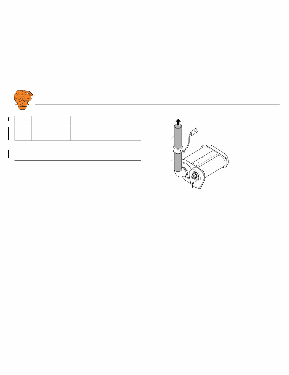
Particulate filter unit
The particulate filter unit consists of an intake with oxidation catalytic converter, a
particulate filter and an outlet. The inlet with oxidation catalytic converter and outlet
can be rotated 360°. The arrows show the exhaust gas direction through the particu-
late filter unit.
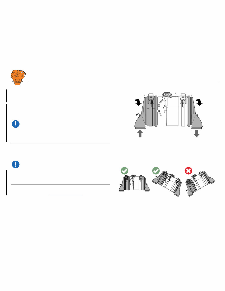
IMPORTANT!
There is a gasket between the oxidation catalytic converter and particulate filter, and
between the particulate filter and outlet. If the components are rotated: Detach the V-
clamps only so much that it is possible to rotate the components and be careful not to
damage the gaskets. Tightening torque: 20 Nm +-3 Nm.
IMPORTANT!
The particulate filter unit must not be positioned so that the oxidation catalytic con-
verter is lower than the particulate filter. There is a channel to the differential pres-
sure sensor inside the particulate filter where condensation may accumulate if the
oxidation catalytic converter is positioned lower than the particulate filter.
The positioning of the particulate filter unit is also limited by the inclination of the
differential pressure sensor. See Differential pressure sensor .
36 0° 36 0°
1
2 3
397 839
Particulate filter unit.
1. Intake and oxidation catalytic converter.
2. Particulate filter.
3. Outlet.
400 845
INSTALLATION
MANUAL
© Scania CV AB 2018, Sweden
Components – Stage V
01:07 Issue 17 en-GB 10
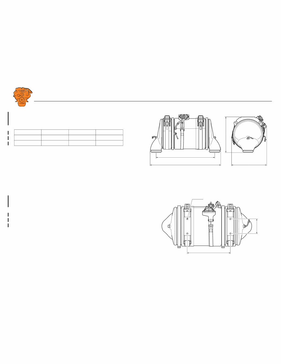
Dimensions and attachment
The particulate filter unit is available in 2 versions. See the illustrations on the right
and below.
The particulate filter unit is supplied with 2 retaining straps with brackets. Attach the
brackets with flange screw M12 or a common screw of a suitable length. Use an M12
flange nut if necessary.
Engine L1 (mm) L2 (mm) L3 (mm)
DC09 603 747 305
DC13 679 823 380
Tightening torques
M12 70 Nm
Retaining strap 39 Nm
425
423
L1
L2
397 837
2x130
L3
4xØ13
397 838
You're Reading a Preview
What's Included?
Lifetime Access
Access PDF Contents & Bookmarks
Print one or all pages of your manual