SENR9983 October 2005 Disassembly and Assembly 1106D Industrial Engine PJ (Engine)
Important Safety Information Most accidents that involve product operation, maintenance and repair are caused by failure to observe basic safety rules or precautions. An accident can often be avoided by recognizing potentially hazardous situations before an accident occurs. A person must be alert to potential hazards. This person should also have the necessary training, skills and tools to perform these functions properly. Improper operation, lubrication, maintenance or repair of this product can be dangerous and could result in injury or death. Do not operate or perform any lubrication, maintenance or repair on this product, until you have read and understood the operation, lubrication, maintenance and repair information. Safety precautions and warnings are provided in this manual and on the product. If these hazard warnings are not heeded, bodily injury or death could occur to you or to other persons. The hazards are identified by the “Safety Alert Symbol” and followed by a “Signal Word” such as “DANGER”, “WARNING” or “CAUTION”. The Safety Alert “WARNING” label is shown below. The meaning of this safety alert symbol is as follows: Attention! Become Alert! Your Safety is Involved. The message that appears under the warning explains the hazard and can be either written or pictorially presented. Operations that may cause product damage are identified by “NOTICE” labels on the product and in this publication. Perkins cannot anticipate every possible circumstance that might involve a potential hazard. The warnings in this publication and on the product are, therefore, not all inclusive. If a tool, procedure, work method or operating technique that is not specifically recommended by Perkins is used, you must satisfy yourself that it is safe for you and for others.You should also ensure that the product will not be damaged or be made unsafe by the operation, lubrication, maintenance or repair procedures that you choose. The information, specifications, and illustrations in this publication are on the basis of information that was available at the time that the publication was written. The specifications, torques, pressures, measurements, adjustments, illustrations, and other items can change at any time. These changes can affect the service that is given to the product. Obtain the complete and most current information before you start any job. Perkins dealers or Perkins distributors have the most current information available. When replacement parts are required for this product Perkins recommends using Perkins replacement parts. Failure to heed this warning can lead to prema- ture failures, product damage, personal injury or death.
SENR9983 3 Table of Contents Table of Contents Disassembly and Assembly Section Fuel Priming Pump - Remove and Install .............. 4 Fuel Filter Base - Remove and Install (Secondary Fuel Filter) ............................................................. 7 Fuel Transfer Pump - Remove ................................ 8 Fuel Transfer Pump - Install .................................. 10 Fuel Injection Lines - Remove .............................. 11 Fuel Injection Lines - Install ................................. 12 Fuel Manifold (Rail) - Remove and Install ............. 14 Fuel Injection Pump - Remove ............................ 16 Fuel Injection Pump - Install ................................ 18 Fuel Injection Pump Gear - Remove .................... 22 Fuel Injection Pump Gear - Install ........................ 23 Electronic Unit Injector - Remove ......................... 25 Electronic Unit Injector - Install ............................. 28 Turbocharger - Remove ........................................ 32 Turbocharger - Disassemble ................................ 35 Turbocharger - Assemble .................................... 35 Turbocharger - Install ............................................ 36 Wastegate Solenoid - Remove and Install ............ 40 Exhaust Manifold - Remove and Install ............... 41 Exhaust Elbow - Remove and Install ................... 45 Inlet Manifold - Remove and Install ..................... 46 Inlet and Exhaust Valve Springs - Remove and Install ................................................................... 48 Inlet and Exhaust Valves - Remove and Install .... 52 Engine Oil Filter Base - Remove and Install ........ 55 Engine Oil Cooler - Remove ................................. 56 Engine Oil Cooler - Install ..................................... 58 Engine Oil Relief Valve - Remove and Install ....... 61 Engine Oil Pump - Remove .................................. 63 Engine Oil Pump - Install ...................................... 64 Water Pump - Remove ......................................... 65 Water Pump - Install ............................................. 66 Water Temperature Regulator - Remove and Install ............................................................................. 67 Flywheel - Remove ............................................... 69 Flywheel - Install ................................................... 70 Crankshaft Rear Seal - Remove ........................... 71 Crankshaft Rear Seal - Install ............................... 72 Crankshaft Wear Sleeve (Rear) - Remove and Install ................................................................... 75 Flywheel Housing - Remove and Install .............. 76 Vibration Damper and Pulley - Remove .............. 81 Vibration Damper and Pulley - Install .................. 82 Crankshaft Front Seal - Remove and Install ......... 84 Crankshaft Wear Sleeve (Front) - Remove and Install ................................................................... 85 Front Cover - Remove and Install ......................... 86 Gear Group (Front) - Remove and Install ............. 88 Idler Gear - Remove ............................................. 91 Idler Gear - Install ................................................. 93 Housing (Front) - Remove .................................... 96 Housing (Front) - Install ........................................ 98 Accessory Drive - Remove and Install ............... 100 Crankcase Breather - Remove ........................... 101 Crankcase Breather - Install ............................... 104 Valve Mechanism Cover - Remove and Install ... 108 Valve Mechanism Cover Base - Remove and Install ................................................................. 109 Rocker Shaft and Pushrod - Remove .................. 111 Rocker Shaft - Disassemble ............................... 112 Rocker Shaft - Assemble .................................... 113 Rocker Shaft and Pushrod - Install ...................... 114 Cylinder Head - Remove ..................................... 116 Cylinder Head - Install ......................................... 118 Lifter Group - Remove and Install ....................... 122 Camshaft - Remove and Install ......................... 123 Camshaft Gear - Remove and Install ................ 125 Camshaft Bearings - Remove and Install .......... 127 Engine Oil Pan - Remove .................................. 129 Engine Oil Pan - Install ...................................... 131 Piston Cooling Jets - Remove and Install ........... 138 Pistons and Connecting Rods - Remove ............ 139 Pistons and Connecting Rods - Disassemble ..... 140 Pistons and Connecting Rods - Assemble ......... 142 Pistons and Connecting Rods - Install ................ 144 Connecting Rod Bearings - Remove (Connecting rods in position) ................................................. 145 Connecting Rod Bearings - Install (Connecting rods in position) ......................................................... 146 Crankshaft Main Bearings - Remove and Install (Crankshaft in position) ..................................... 148 Crankshaft - Remove .......................................... 151 Crankshaft - Install .............................................. 152 Crankshaft Timing Ring - Remove and Install .... 155 Crankshaft Gear - Remove and Install .............. 156 Bearing Clearance - Check ................................. 158 Crankshaft Position Sensor - Remove and Install ................................................................. 159 Coolant Temperature Sensor - Remove and Install ................................................................. 159 Engine Oil Pressure Sensor - Remove and Install ........................................................................... 161 Position Sensor (Fuel Injection Pump) - Remove and Install ................................................................. 162 Fuel Pressure Sensor - Remove and Install ....... 163 Boost Pressure Sensor - Remove and Install ..... 164 Inlet Air Temperature Sensor - Remove and Install ................................................................. 165 Glow Plugs - Remove and Install ....................... 166 Alternator Belt - Remove and Install .................. 167 Fan - Remove and Install ................................... 168 Fan Drive - Remove and Install ......................... 169 Electronic Control Module - Remove and Install .. 170 ECM Mounting Bracket - Remove and Install ..... 172 Alternator - Remove ............................................ 175 Alternator - Install ................................................ 176 Electric Starting Motor - Remove and Install ..... 177 Index Section Index ................................................................... 178
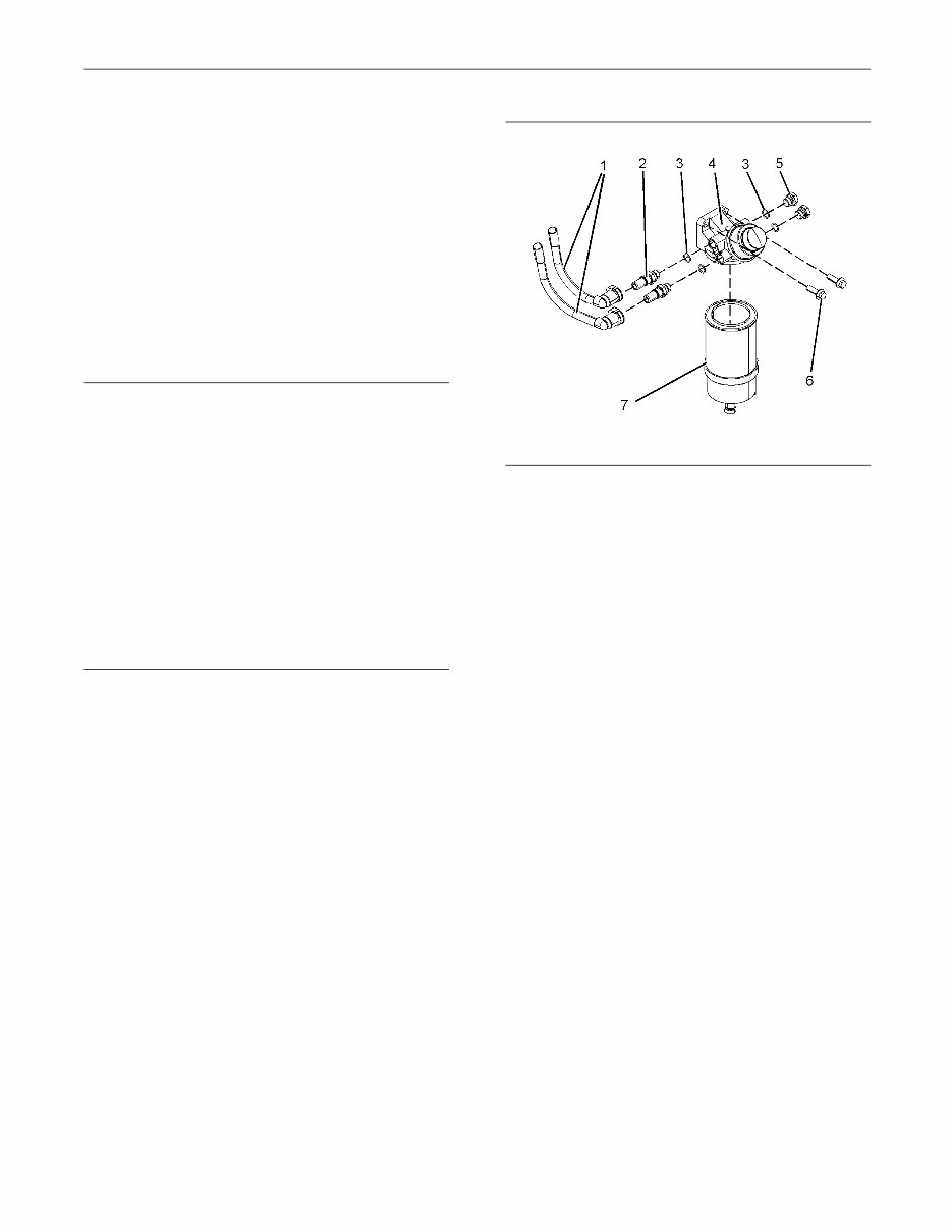
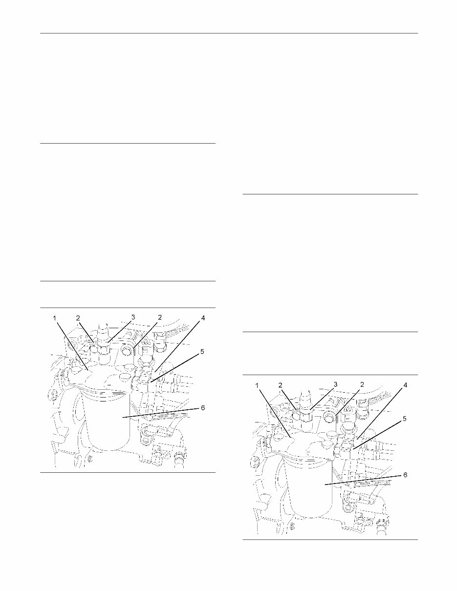
4 SENR9983 Disassembly and Assembly Section Disassembly and Assembly Section i02295884 Fuel Priming Pump - Remove and Install Removal Procedure (Manual Priming Pump) NOTICE Ensure that all adjustments and repairs that are carried out to the fuel system are performed by authorised personnel that have the correct train- ing. Before begining ANY work on the fuel system, re- fer to Operation and Maintenance Manual, “Gen- eral Hazard Information and High Pressure Fuel Lines” for safety information. Refer to Testing and Adjusting Manual, “Clean- liness of Fuel System Components” for detailed information on the standards of cleanliness that must be observed during ALL work on the fuel system. 1. Isolate the fuel supply. 2. Make a temporary identification mark on the plastic tube assemblies (1) in order to show the correct position of the tube assemblies. 3. Place a suitable container below the fuel priming pump in order to catch any fuel that might be spilled. Drain the primary filter (7). Refer to Operation and Maintenance Manual, “Fuel System Primary Filter (Water Seperator) Element - Replace”. Note: Clean up any spillage of fuel immediately. g01181971 Illustration 1 Typical example 4. Disconnect the plastic tube assemblies (1). Plug the tube assemblies with new plugs. Cap the open connectors (2) on the fuel priming pump with new caps. 5. Remove the primary filter (7) from the fuel priming pump (4). Refer to Operation and Maintenance Manual, “Fuel System Primary Filter (Water Seperator) Element - Replace”. 6. Remove the two setscrews (6) from the fuel priming pump (4). Remove the fuel priming pump (4) from the mounting bracket. 7. If necessary, follow Steps 7.a through 7.c in order to disassemble the fuel priming pump (4). a. Remove the connectors (2) from the fuel priming pump (4). b. Remove the plugs (5) from the fuel priming pump (4). c. Remove the O-ring seals (3) from the connectors (2) and the plugs (5). Discard the O-ring seals.
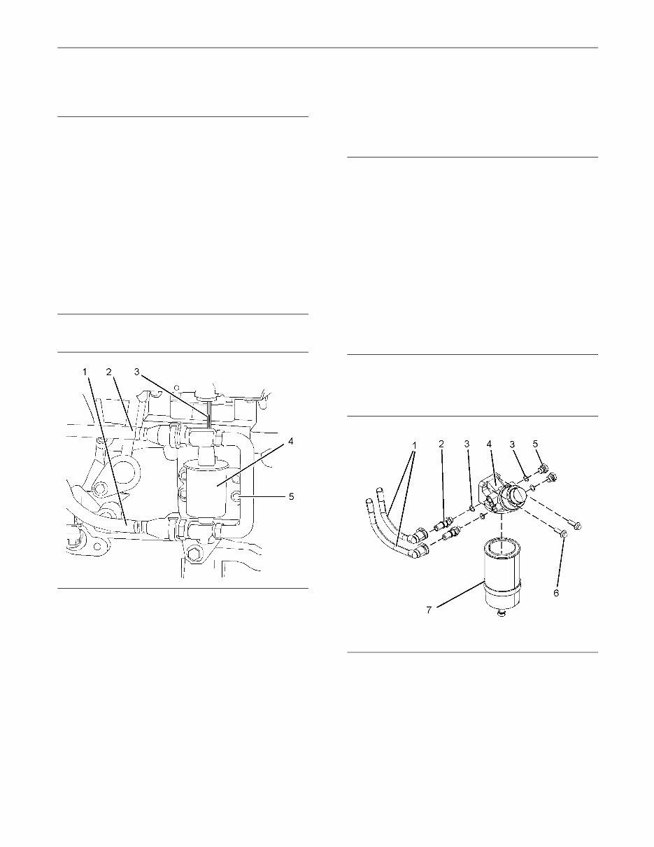
SENR9983 5 Disassembly and Assembly Section Removal Procedure (Electric Fuel Priming Pump) NOTICE Ensure that all adjustments and repairs that are carried out to the fuel system are performed by authorised personnel that have the correct train- ing. Before begining ANY work on the fuel system, re- fer to Operation and Maintenance Manual, “Gen- eral Hazard Information and High Pressure Fuel Lines” for safety information. Refer to Testing and Adjusting Manual, “Clean- liness of Fuel System Components” for detailed information on the standards of cleanliness that must be observed during ALL work on the fuel system. 1. Isolate the fuel supply. g01186418 Illustration 2 Typical example 2. Isolate the electrical supply. 3. Disconnect the electrical lead (3) for the electric priming pump (4). 4. Make a temporary identification mark on the plastic tube assemblies (1) and (2) in order to show the correct position of the tube assemblies. 5. Disconnect the plastic tube assemblies (1) and (2). Plug the tube assemblies with new plugs. Cap the ports in the fuel priming pump (4) with new caps. 6. Remove the four setscrews (5) from the electric priming pump (4). 7. Remove the electric priming pump (4) from the mounting bracket. Installation Procedure (Manual Priming Pump) NOTICE Ensure that all adjustments and repairs that are carried out to the fuel system are performed by authorised personnel that have the correct train- ing. Before begining ANY work on the fuel system, re- fer to Operation and Maintenance Manual, “Gen- eral Hazard Information and High Pressure Fuel Lines” for safety information. Refer to Testing and Adjusting Manual, “Clean- liness of Fuel System Components” for detailed information on the standards of cleanliness that must be observed during ALL work on the fuel system. 1. Ensure that the fuel priming pump (4) is clean and free from wear or damage. If necessary, replace the fuel priming pump. g01181971 Illustration 3 Typical example 2. If necessary, follow Steps 2.a through 2.d in order to assemble the fuel priming pump (4). a. Install new O-ring seals (3) to the connectors (2) and to the plugs (5). b. Install the connectors (2) to the fuel priming pump (4). c. Install the plugs (5) to the fuel priming pump (4).
6 SENR9983 Disassembly and Assembly Section d. Tighten the plugs and the connectors to a torque of 20 N·m (14 lb ft). 3. Position the fuel priming pump (4) on the mounting bracket. Install the two setscrews (6) to the fuel priming pump . Tighten the setscrews to a torque of 44 N·m (32 lb ft). 4. Remove the plugs from the plastic tube assemblies. Remove the caps from the connectors. 5. Connect the plastic tube assemblies (1) to the connectors (2). Note: Ensure that the plastic tube assemblies are installed in the original positions. 6. Install a new primary filter (7) to the fuel priming pump (4). Refer to Operation and Maintenance Manual, “Fuel System Primary Filter (Water Seperator) Element - Replace”. 7. Restore the fuel supply. 8. Prime the fuel system. Refer to Operation and Maintenance Manual, “Fuel System - Prime”. Installation Procedure (Electric Fuel Priming Pump) NOTICE Ensure that all adjustments and repairs that are carried out to the fuel system are performed by authorised personnel that have the correct train- ing. Before begining ANY work on the fuel system, re- fer to Operation and Maintenance Manual, “Gen- eral Hazard Information and High Pressure Fuel Lines” for safety information. Refer to Testing and Adjusting Manual, “Clean- liness of Fuel System Components” for detailed information on the standards of cleanliness that must be observed during ALL work on the fuel system. 1. Ensure that the electric priming pump (4) is clean and free from wear or damage. If necessary, replace the electric priming pump. g01186418 Illustration 4 Typical example 2. Position the electric priming pump (4) on the mounting bracket. Install the four setscrews (5) to the electric priming pump (4). 3. Tighten the setscrews (5) to a torque of 9 N·m (79 lb in). 4. Remove the plugs from the plastic tube assemblies. Remove the caps from the electric priming pump. 5. Connect the plastic tube assemblies (1) and (2) to the electric priming pump (4). Note: Ensure that the plastic tube assemblies are installed in the original positions. 6. Connect the electrical lead (3) for the electric priming pump (4). 7. Restore the electrical supply. 8. Restore the fuel supply. 9. Prime the fuel system. Refer to Operation and Maintenance Manual, “Fuel System - Prime”.
SENR9983 7 Disassembly and Assembly Section i02295889 Fuel Filter Base - Remove and Install (Secondary Fuel Filter) Removal Procedure NOTICE Ensure that all adjustments and repairs that are carried out to the fuel system are performed by authorised personnel that have the correct train- ing. Before begining ANY work on the fuel system, re- fer to Operation and Maintenance Manual, “Gen- eral Hazard Information and High Pressure Fuel Lines” for safety information. Refer to Testing and Adjusting Manual, “Clean- liness of Fuel System Components” for detailed information on the standards of cleanliness that must be observed during ALL work on the fuel system. 1. Isolate the fuel supply. g01165584 Illustration 5 Typical example 2. Make temporary identification marks on the plastic tube assemblies (3), (4) and (5) in order to show the correct position of the tube assemblies. 3. Place a suitable container below the fuel filter base in order to catch any fuel that might be spilled. Note: Clean up any spillage of fuel immediately. 4. Disconnect the plastic tube assemblies (3), (4) and (5) from the fuel filter base (1). Plug the plastic tube assemblies with new plugs. Cap the ports in the fuel filter base with new caps. 5. Remove the fuel filter (6). Refer to Operation and Maintenance Manual, “Fuel System Secondary Filter - Replace”. 6. Remove the two setscrews (2) from the fuel filter base (1). Remove the fuel filter base from the mounting bracket. Note: Do not disassemble the fuel filter base. Installation Procedure NOTICE Ensure that all adjustments and repairs that are carried out to the fuel system are performed by authorised personnel that have the correct train- ing. Before begining ANY work on the fuel system, re- fer to Operation and Maintenance Manual, “Gen- eral Hazard Information and High Pressure Fuel Lines” for safety information. Refer to Testing and Adjusting Manual, “Clean- liness of Fuel System Components” for detailed information on the standards of cleanliness that must be observed during ALL work on the fuel system. 1. Ensure that the fuel filter base (1) is clean and free from damage. If necessary, replace the complete fuel filter base and filter assembly. g01165584 Illustration 6 Typical example
8 SENR9983 Disassembly and Assembly Section 2. Position the fuel filter base (1) on the mounting bracket. Install the setscrews (2). Tighten the setscrews to a torque of 44 N·m (32 lb ft). 3. Remove the plugs from the plastic tube assemblies. Remove the caps from the ports in the fuel filter base. NOTICE Ensure that the plastic tube assemblies are installed in the original positions. Failure to connect the plastic tube assemblies to the correct ports will allow contam- ination to enter the fuel system. Contaminated fuel will cause serious damage to the engine. 4. Connect the plastic tube assemblies (3), (4) and (5) to the fuel filter base (1). Note: Ensure that the plastic tube assemblies are installed in the original positions. Failure to connect the plastic tube assemblies to the correct ports will allow contamination to enter the fuel system. Contaminated fuel will cause serious damage to the engine. 5. If necessary, install a new fuel filter (6) to the fuel filter base (1). Refer to Operation and Maintenance Manual, “Fuel System Secondary Filter - Replace” for the correct procedure. 6. Restore the fuel supply. End By: a. Remove the air from the fuel system. Refer to Operation and Maintenance Manual, “Fuel System - Prime”. i02296828 Fuel Transfer Pump - Remove Removal Procedure NOTICE Ensure that all adjustments and repairs that are carried out to the fuel system are performed by authorised personnel that have the correct train- ing. Before begining ANY work on the fuel system, re- fer to Operation and Maintenance Manual, “Gen- eral Hazard Information and High Pressure Fuel Lines” for safety information. Refer to Testing and Adjusting Manual, “Clean- liness of Fuel System Components” for detailed information on the standards of cleanliness that must be observed during ALL work on the fuel system. 1. Isolate the fuel supply. 2. Place a suitable container below the fuel transfer pump (1) in order to catch any fuel that might be spilled. Note: Clean up any spillage of fuel immediately.
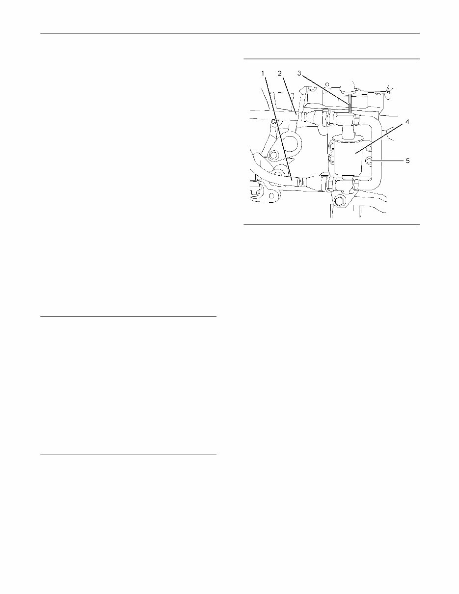
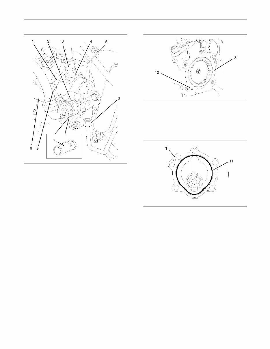
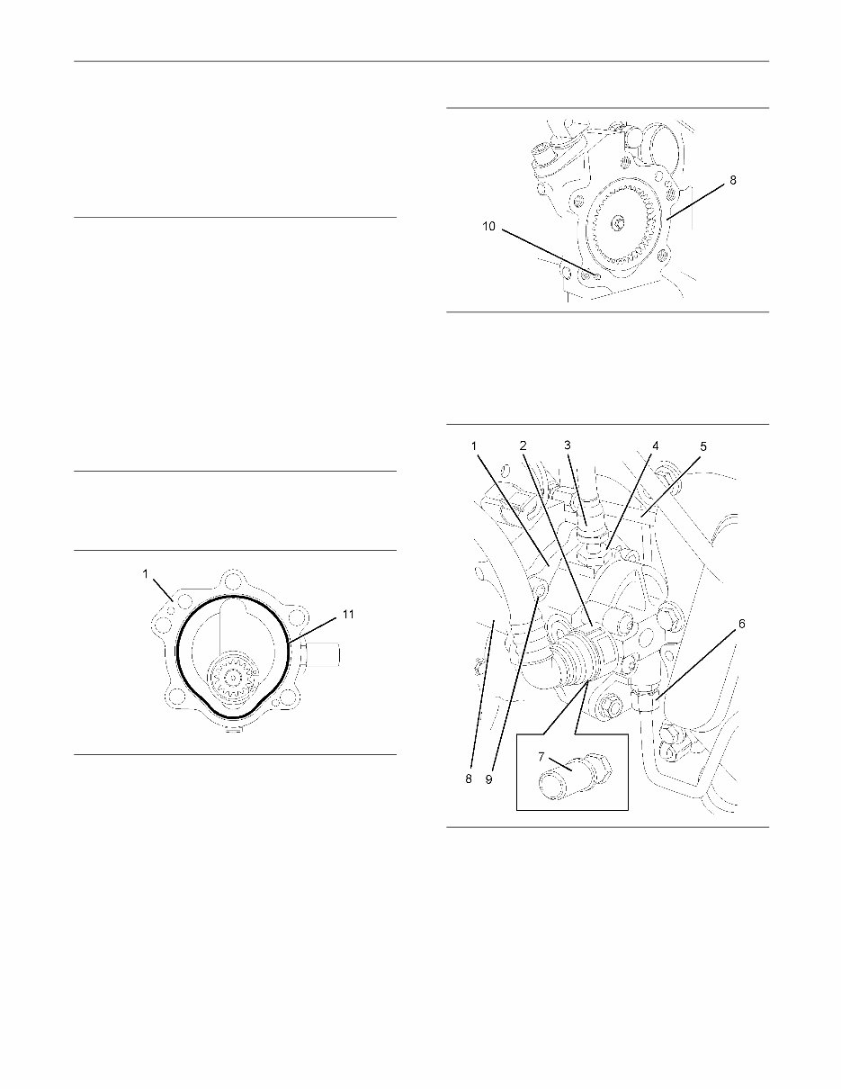
SENR9983 9 Disassembly and Assembly Section g01162545 Illustration 7 Typical example 3. Remove the plastic tube assembly (2) from the fuel transfer pump (1). 4. Disconnect the plastic tube assembly (3) from the outlet of the fuel transfer pump (1). 5. Remove the connector (4) from the fuel transfer pump (1). Remove the O-ring seal (not shown) from the connector (4). Discard the O-ring seal. If necessary, remove the connector (7) from the fuel transfer pump (1). Remove the O-ring seal (not shown) from the connector (7). Discard the O-ring seal. 6. Remove the tube assembly (6) for the fuel return from the fuel transfer pump and the cylinder head. Note: Disconnect the tube assembly at the fuel transfer pump first in order to drain the fuel from the cylinder head. 7. Remove the tube assembly (5) for the engine oil supply from the fuel injection pump (8). 8. Plug or cap all open ports and tube assemblies immediately with new plugs or caps. 9. Use an allen wrench with a ball end in order to remove the five allen head screws (9) that secure the fuel transfer pump to the fuel injection pump (8). g01162543 Illustration 8 10. Remove fuel transfer pump (1) from the fuel injection pump (8). Note: Do not remove the dowels (10) from the fuel injection pump. g01162544 Illustration 9 11. Remove the O-ring seal (11) from the fuel transfer pump (1). Discard the O-ring seal.
10 SENR9983 Disassembly and Assembly Section i02296829 Fuel Transfer Pump - Install Installation Procedure NOTICE Ensure that all adjustments and repairs that are carried out to the fuel system are performed by authorised personnel that have the correct train- ing. Before begining ANY work on the fuel system, re- fer to Operation and Maintenance Manual, “Gen- eral Hazard Information and High Pressure Fuel Lines” for safety information. Refer to Testing and Adjusting Manual, “Clean- liness of Fuel System Components” for detailed information on the standards of cleanliness that must be observed during ALL work on the fuel system. 1. Ensure that the mating faces of the fuel injection pump (8) and the fuel transfer pump (1) are clean and free from damage. g01162544 Illustration 10 2. Install a new O-ring seal (11) to fuel transfer pump (1). Lubricate the O-ring seal with clean engine oil. g01162543 Illustration 11 3. Align the holes in the fuel transfer pump (1) with the dowels (10) in the fuel injection pump (8). Install the fuel transfer pump to the fuel injection pump. g01162545 Illustration 12 Typical example 4. Use an allen wrench with a ball end to install the five allen head screws (9). Tighten the allen head screws to a torque of 30 N·m (22 lb ft). 5. Remove the plugs and the caps from the ports and tube assemblies.
This manual provides detailed service information, step-by-step repair instruction, and maintenance specifications for The Perkins 1100 Series 6-Cylinder, (model VK) Diesel Engines.
Applicable Models:
Perkins 1100 Series - Model VK
6 cylinder diesel engines for agricultural, industrial, and construction applications
Table of Contents:
General information
Specifications
Cylinder head assembly
Piston and connecting rod assemblies
Crankshaft assembly
Timing case and drive assembly
Cylinder block assembly
Engine timing
Aspiration system
Lubrication system
Fuel system
Cooling system
Flywheel and housing
Electrical equipment
Auxiliary equipment
Special tools
Language: English
Requirements: Reader
Total pages: 304
This manual contains specs, diagrams, actual real photo illustrations, and schemes. In addition to space savings, the benefit of having files instead of a hard-printed manual is that you can use the Search feature in Acrobat to find just what you're looking for and print out the exact pages you need or the entire manual.
→ This Manual Compatible with All version Windows PC OS, MAC OS, and Linux OS.
→ Compression utility needed to extract it first, if located in the archive (e.g. 7- ).
→ All pages are printable, so run off what you need & take it with you into the garage or workshop.