Important Safety Information Most accidents that involve product operation, maintenance and repair are caused by failure to observe basic safety rules or precautions. An accident can often be avoided by recognizing potentially hazardous situations before an accident occurs. A person must be alert to potential hazards. This person should also have the necessary training, skills and tools to perform these functions properly. Improper operation, lubrication, maintenance or repair of this product can be dangerous and could result in injury or death. Do not operate or perform any lubrication, maintenance or repair on this product, until you have read and understood the operation, lubrication, maintenance and repair information. Safety precautions and warnings are provided in this manual and on the product. If these hazard warnings are not heeded, bodily injury or death could occur to you or to other persons. The hazards are identified by the “Safety Alert Symbol” and followed by a “Signal Word” such as “DANGER”, “WARNING” or “CAUTION”. The Safety Alert “WARNING” label is shown below. The meaning of this safety alert symbol is as follows: Attention! Become Alert! Your Safety is Involved. The message that appears under the warning explains the hazard and can be either written or pictorially presented. Operations that may cause product damage are identified by “NOTICE” labels on the product and in this publication. Perkins cannot anticipate every possible circumstance that might involve a potential hazard. The warnings in this publication and on the product are, therefore, not all inclusive. If a tool, procedure, work method or operating technique that is not specifically recommended by Perkins is used, you must satisfy yourself that it is safe for you and for others.You should also ensure that the product will not be damaged or be made unsafe by the operation, lubrication, maintenance or repair procedures that you choose. The information, specifications, and illustrations in this publication are on the basis of information that was available at the time that the publication was written. The specifications, torques, pressures, measurements, adjustments, illustrations, and other items can change at any time. These changes can affect the service that is given to the product. Obtain the complete and most current information before you start any job. Perkins dealers or Perkins distributors have the most current information available. When replacement parts are required for this product Perkins recommends using Perkins replacement parts. Failure to heed this warning can lead to prema- ture failures, product damage, personal injury or death.
3 Table of Contents Table of Contents Systems Operation Section Engine Design ....................................................... 4 General Information ................................................ 5 Fuel System ........................................................... 9 Air Inlet and Exhaust System ............................... 10 Lubrication System .............................................. 13 Cooling System .................................................... 16 Basic Engine ......................................................... 17 Electrical System ................................................. 19 Testing and Adjusting Section Fuel System Fuel System - Inspect ........................................... 22 Air in Fuel - Test .................................................... 22 Finding Top Center Position for No. 1 Piston ........ 23 Fuel Injection Pump Timing - Check ..................... 24 Fuel Injection Pump Timing - Adjust ..................... 25 Fuel Quality - Test ................................................. 27 Fuel System - Prime ............................................. 27 Fuel System Pressure - Test ................................. 28 Air Inlet and Exhaust System Air Inlet and Exhaust System - Inspect ................. 29 Wastegate - Test ................................................... 29 Compression - Test ............................................... 30 Engine Valve Lash - Inspect/Adjust ...................... 30 Valve Depth - Inspect ............................................ 33 Valve Guide - Inspect ............................................ 33 Lubrication System Engine Oil Pressure - Test .................................... 35 Engine Oil Pump - Inspect .................................... 35 Excessive Bearing Wear - Inspect ........................ 36 Excessive Engine Oil Consumption - Inspect ....... 36 Increased Engine Oil Temperature - Inspect ........ 37 Cooling System Cooling System - Check (Overheating) ................ 38 Cooling System - Inspect ...................................... 39 Cooling System - Test ........................................... 39 Engine Oil Cooler - Inspect ................................... 41 Water Temperature Regulator - Test ..................... 42 Basic Engine Piston Ring Groove - Inspect ................................ 43 Connecting Rod - Inspect ..................................... 43 Connecting Rod Bearings - Inspect ...................... 44 Main Bearings - Inspect ........................................ 44 Cylinder Block - Inspect ........................................ 44 Cylinder Head - Inspect ........................................ 45 Piston Height - Inspect .......................................... 45 Flywheel - Inspect ................................................. 46 Gear Group - Inspect ............................................ 47 Electrical System Alternator - Test .................................................... 48 Battery - Test ......................................................... 48 Electric Starting System - Test .............................. 49 Glow Plugs - Test .................................................. 51 V-Belt - Test .......................................................... 52 Index Section Index ..................................................................... 53
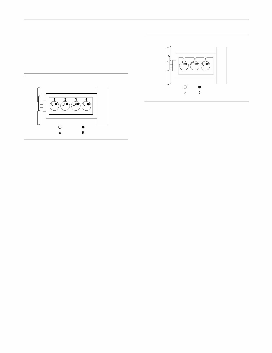
4 Systems Operation Section Systems Operation Section i01958113 Engine Design g00984281 Illustration 1 1104 example of the layout of the valves (A) Inlet valve (B) Exhaust valve 1104 Engine Specification Type ............................ Four cylinder and four stroke Type of combustion ............................ Direct injection Bore ......................................... 105 mm (4.133 inch) Stroke ........................................ 127 mm (5.00 inch) Displacement ...................................... 4.4 L (268 in 3 ) Compression ratio Naturally aspirated .......................................... 19.3:1 Turbocharged .................................................. 18.2:1 Number of cylinders ................................................ 4 Cylinder arrangement ..................................... In-line Firing order ................................................ 1, 3, 4, 2 When the crankshaft is viewed from the front of the engine, the crankshaft rotates in the following direction. ................................................... Clockwise The front of the engine is opposite the flywheel end of the engine. The left side of the engine and the right side of the engine are determined from the flywheel end. Number 1 cylinder is the front cylinder of the engine. g01014247 Illustration 2 1103 example of the layout of the valves (A) Inlet valve (B) Exhaust valve 1103 Engine Specification Type .......................... Three cylinder and four stroke Type of combustion ............................ Direct injection Bore ......................................... 105 mm (4.133 inch) Stroke ........................................ 127 mm (5.00 inch) Displacement ...................................... 3.3 L (201 in 3 ) Compression ratio Naturally aspirated .......................................... 19.2:1 Turbocharged ................................................ 18.25:1 Number of cylinders ................................................ 3 Cylinder arrangement ..................................... In-line Firing order ..................................................... 1, 2, 3 When the crankshaft is viewed from the front of the engine, the crankshaft rotates in the following direction. ................................................... Clockwise The front of the engine is opposite the flywheel end of the engine. The left side of the engine and the right side of the engine are determined from the flywheel end. Number 1 cylinder is the front cylinder of the engine.
5 Systems Operation Section i01958097 General Information Engine Description Note: When you are ordering new parts, refer to the engine identification number in order to receive the correct parts. Refer to the Operation and Maintenance Manual, “Product Identification Information” for the correct numbers for your engine. The engine cylinders are arranged in-line. The engines are controlled by a mechanically governed fuel injection pump. The cylinder head assembly has one inlet valve and one exhaust valve for each cylinder. Each valve has one valve spring. The pistons have two compression rings and an oil control ring. It is important to ensure the correct piston height so that the piston does not contact the cylinder head. The correct piston height also ensures the efficient combustion of fuel. The 1104 engine crankshaft has five main journals. End play is controlled by thrust washers that are located on both sides of the center main bearing. The 1103 engine crankshaft has four main journals. End play is controlled by thrust washers that are located on both sides of the number three main bearing. The timing case has a hole that corresponds with a hole in the crankshaft. Use an alignment pin to find TC. The camshaft gear has a timing hole that corresponds with a timing hole in the timing case. The timing holes ensure that the camshaft and the crankshaft are in time with each other. The crankshaft gear rotates the idler gear. The idler gear rotates the camshaft gear and the fuel injection pump gear. The idler gear for the engine oil pump is rotated by the crankshaft gear. This idler rotates the engine oil pump. The fuel injection pump is a gear-driven pump that is mounted to the back of the front housing. The fuel transfer pump is electrically operated. The fuel transfer pump has an integral fuel filter. The fuel transfer pump is usually located on the left hand side of the cylinder block. Some applications may have the fuel transfer pump and the water separator (if equipped) relocated off the engine. The oil pump is driven by an idler gear. The engine oil pump sends lubricating oil to the main oil gallery. The oil relief valve is internal to the oil pump. Coolant from the bottom of the radiator passes through the water pump. The water pump is driven by the idler gear. Lifting the Engine NOTICE Failure to follow recommended procedures for han- dling or transporting engines can lead to engine dam- age. To avoid possible engine damage, use the following procedure. When you are lifting or moving the engine, use the following procedures in order to prevent engine damage. 1. Do not tilt the engine to an extreme angle unless the lubricating oil is first drained from the oil pan. 2. Do not turn the engine onto a side or an end surface unless the lubricating oil is first drained from the oil pan. 3. If the oil is not drained prior to tilting the engine or turning the engine onto a side or an end surface, the lubricating oil from the oil pan can flow into the intake manifold and the cylinder bores. This situation could cause a hydraulic lock in the engine. Hydraulic lock can severely damage the engine. 4. The engine oil should be refilled to the correct level before the engine is started.
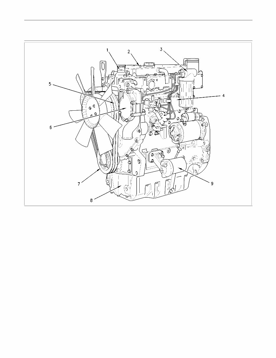
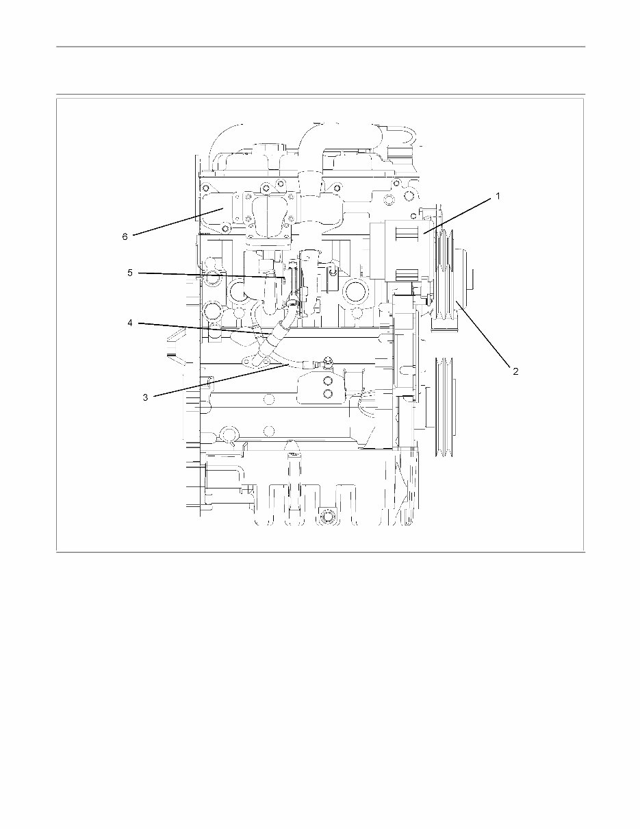
6 Systems Operation Section 1104 Engine Model Views g00993373 Illustration 3 (1) Water temperature regulator housing (2) Valve mechanism cover (3) Fuel transfer pump and fuel filter (4) Engine oil cooler (5) Fan drive (6) Water pump (7) Crankshaft pulley (8) Oil pan (9) Engine oil filter
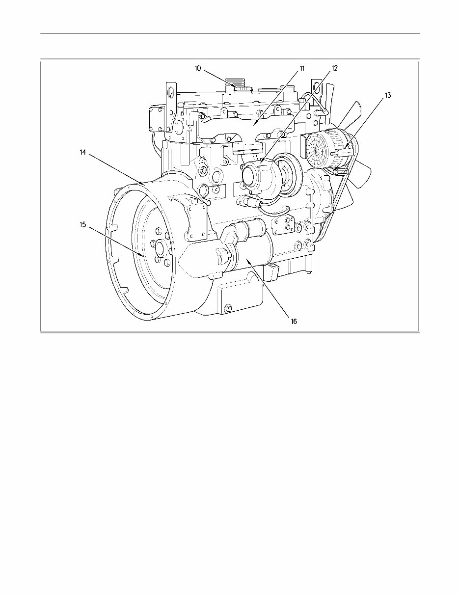
7 Systems Operation Section g00928546 Illustration 4 (10) Engine oil filler cap (11) Exhaust manifold (12) Turbocharger (13) Alternator (14) Flywheel housing (15) Flywheel (16) Starter motor
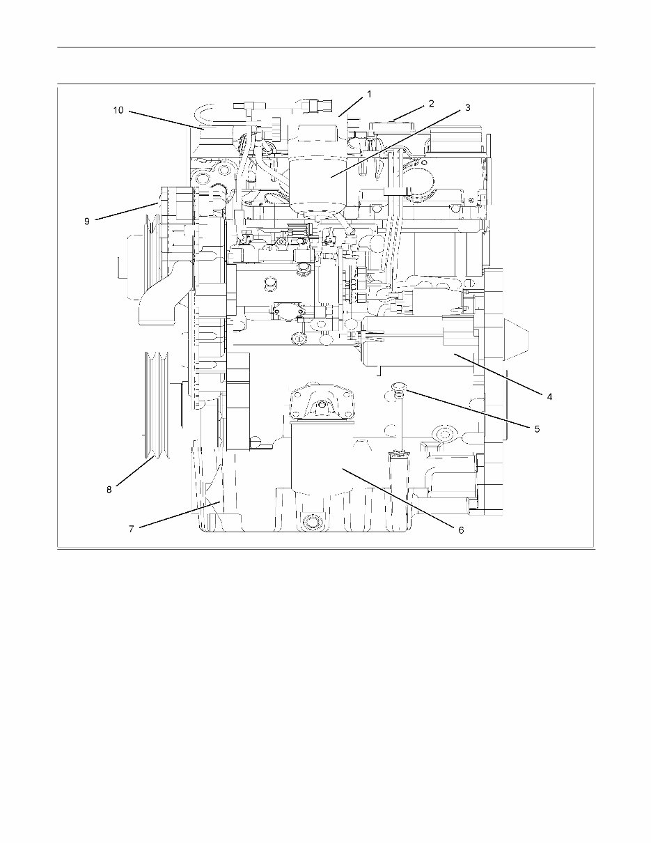
8 Systems Operation Section 1103 Engine Model Views g01011348 Illustration 5 (1) Alternator (2) Fan pulley (3) Turbocharger oil supply (4) Turbocharger oil drain (5) Turbocharger (6) Exhaust manifold
9 Systems Operation Section g01011349 Illustration 6 (1) Fuel transfer pump (2) Oil filler cap (3) Fuel filter (4) Starter motor (5) Dipstick (6) Oil filter (7) Oil pan (8) Crankshaft pulley (9) Water pump (10) Water temperature regulator housing i02074845 Fuel System The Delphi DP210 fuel injection pump is installed on the 1104 engine and the 1103 engine. The Delphi STP fuel injection pump is installed on the 1103 engine only. The Bosch EPVE fuel injection pump is installed on the 1104 engine only. The fuel transfer pump draws fuel from the fuel tank and through the water separator. When the fuel goes through the water separator, any water in the fuel will go to the bottom of the bowl. The fuel transfer pump sends the fuel at a low pressure to the fuel filter. From the fuel filter, the fuel goes through the supply line to the fuel injection pump. The fuel injection pump sends fuel through the high pressure fuel line to each of the fuel injectors. The fuel injector sprays the fuel into the cylinder. Fuel that is not injected flows through the fuel return line to the top of the fuel filter, back to the fuel tank.
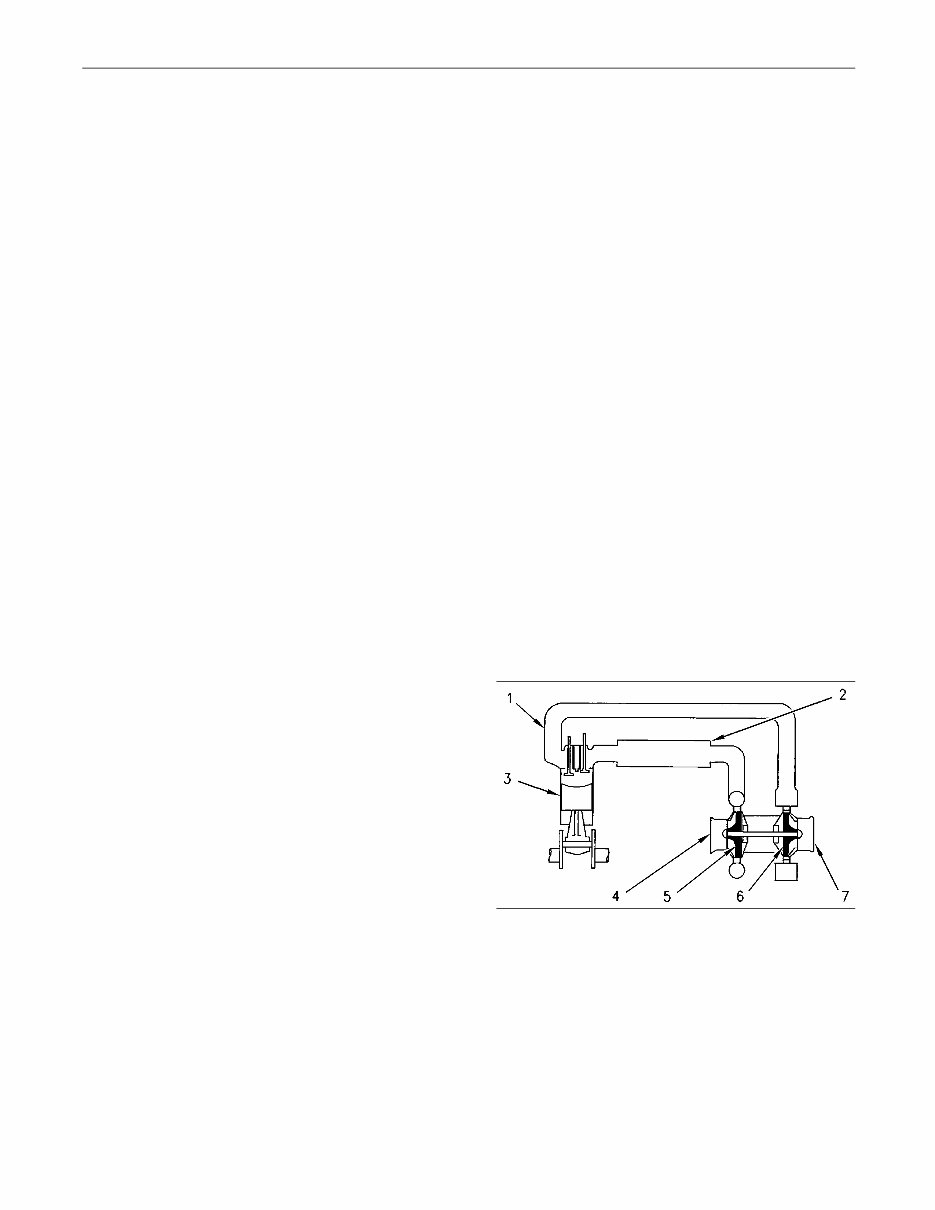
10 Systems Operation Section The engine must not be started until the fuel injection pump is full of fuel that is free of air. The fuel injection pump requires fuel for lubrication. The precision parts of the pump are easily damaged without lubrication. The fuel system must be primed when any of the following conditions occur: • The fuel filter is changed. • The fuel line is removed. • The fuel injection pump is removed. Fuel System Components Fuel Injection Pump General Operation The fuel injection pump is a pressurized system that is totally enclosed. The pump sends the correct amount of fuel under high pressure at the correct time through the fuel injectors to the individual cylinders. The fuel injection pump regulates the amount of fuel that is delivered to the fuel injectors. This action controls the engine rpm by the governor setting or the position of the throttle control. The fuel lines to the fuel injectors are equal lengths. This ensures even pressure and correct injection timing at each fuel injector. During operation, extra fuel is used as coolant and lubricant for moving parts of the pump. The extra fuel is circulated through the pump housing. The extra fuel is then returned to the fuel tank. The Delphi DP210 and the Delphi STP fuel injection pumps must be serviced by an authorized Delphi technician. For repair information, contact your Perkins dealer or contact your Perkins distributor. High idle and low idle of the fuel injection pump are factory set. Idle adjustments can not be made to the fuel pump. The Delphi DP210 fuel injection pump has a boost control . The Delphi DP210 and the Delphi STP fuel injection pumps have a engine stop solenoid. The Delphi DP210 and the Delphi STP fuel injection pumps have a feature that vents air from the pump. The fuel injection pump has a cold starting aid. The cold starting aid advances the timing of the pump when the engine is cold. The cold starting aid is electrically operated. Cold Start Advance Unit The cold start advance unit holds the timing of the fuel injection pump in an advance position when the engine is cold. The coolant switch for the cold start advance unit is on the rear of the timing case on the left side of the engine. When the engine is cold, the sender unit is energized in order to advance the fuel injection pump timing for the cold start operation. When the correct temperature is achieved the sender unit is de-energized and the fuel injection pump timing is returned to the normal operating position. If the switch fails in the closed position, the engine will run with advanced fuel injection timing. The engine will have higher cylinder pressure and engine damage may result. If the switch fails in the open position the engine will run with the fuel injection timing in the normal operating position. The engine will be more difficult to start. When the engine is cold the engine might emit white smoke. i01912948 Air Inlet and Exhaust System g00281646 Illustration 7 Air inlet and exhaust system (typical example) (1) Exhaust manifold (2) Intake manifold (3) Engine cylinders (4) Air intake (5) Turbocharger compressor wheel (6) Turbocharger turbine wheel (7) Exhaust outlet
The PERKINS 1104C Testing & Adjusting Engines workshop service repair manual is a comprehensive guide that provides troubleshooting solutions, servicing specifications, tightening torques, and step-by-step instructions for checking, disassembling, and servicing the engine. With this Workshop Service Repair Manual, both professional mechanics and DIY enthusiasts will gain a deep understanding of the engine's mechanism, as well as the proper procedures for servicing and maintaining the engine's mechanical system, electrical system, fuel system, and more. This manual is essential for anyone working with PERKINS 1104C engines, ensuring that they have the knowledge and resources to keep these engines running smoothly.