EM-1 ENGINE MECHANICAL B ENGINE CONTENTS C D E F G H I J K L M SECTION A EM ENGINE MECHANICAL KA24DE PRECAUTIONS ......................................................... 5 Precautions for Drain Coolant ................................. 5 Precautions for Disconnecting Fuel Piping ............. 5 Precautions for Removal and Disassembly ............ 5 Precautions for Inspection, Repair and Replace- ment ........................................................................ 5 Precautions for Assembly and Installation .............. 5 Parts Requiring Angular Tightening ........................ 5 Precautions for Liquid Gasket ................................. 6 REMOVAL OF LIQUID GASKET SEALING ......... 6 LIQUID GASKET APPLICATION PROCEDURE ..... 6 PREPARATION .......................................................... 7 Special Service Tools .............................................. 7 Commercial Service Tools ....................................... 8 NOISE, VIBRATION, AND HARSHNESS (NVH) TROUBLESHOOTING ............................................. 10 NVH Troubleshooting —Engine Noise .................. 10 Use the Chart Below to Help You Find the Cause of the Symptom. ..................................................... 11 ENGINE ROOM COVER ......................................... 12 Removal and Installation of Engine Room Right Side ....................................................................... 12 REMOVAL .......................................................... 12 INSTALLTION .................................................... 12 Removal and Installation of Engine Room Rear Cover ..................................................................... 12 REMOVAL .......................................................... 12 INSTALLATION .................................................. 13 DRIVE BELTS .......................................................... 14 Checking Drive Belts ............................................. 14 Tension Adjustment ............................................... 14 POWER STEERING PUMP BELT ..................... 14 AIR CONDITIONER COMPRESSOR BELT ...... 14 ALTERNATOR AND WATER PUMP BELT ........ 15 Removal and Installation ....................................... 15 REMOVAL .......................................................... 15 INSTALLATION .................................................. 15 AIR CLEANER AND AIR DUCT .............................. 16 Removal and Installation ....................................... 16 REMOVAL .......................................................... 16 INSTALLATION .................................................. 17 Changing Air Cleaner Element .............................. 18 REMOVAL .......................................................... 18 INSTALLATION .................................................. 18 THROTTLE BODY ................................................... 19 Removal and Installation ....................................... 19 REMOVAL .......................................................... 19 INSPECTION AFTER REMOVAL ...................... 20 INSTALLATION .................................................. 20 Disassembly and Assembly ................................... 20 DISASSEMBLY .................................................. 20 ASSEMBLY ........................................................ 20 INTAKE MANIFOLD ................................................ 21 Removal and Installation ....................................... 21 REMOVAL .......................................................... 21 INSPECTION AFTER REMOVAL ...................... 22 INSTALLATION .................................................. 22 EXHAUST MANIFOLD ............................................ 23 Removal and Installation ....................................... 23 REMOVAL .......................................................... 23 INSPECTION AFTER REMOVAL ...................... 24 INSTALLATION .................................................. 24 INSPECTION AFTER INSTALLATION ............... 24 OIL PAN AND OIL STRAINER ................................ 25 Removal and Installation ....................................... 25 REMOVAL .......................................................... 25 INSPECTION AFTER REMOVAL ...................... 25 INSTALLATION .................................................. 25 INSPECTION AFTER INSTALLATION ............... 26 SPARK PLUG (CONVENTIONAL) .......................... 27 Removal and Installation ....................................... 27 REMOVAL .......................................................... 27 INSPECTION AFTER REMOVAL ...................... 27 INSTALLATION .................................................. 27 FUEL INJECTOR AND FUEL TUBE ....................... 28 Removal and Installation ....................................... 28 REMOVAL .......................................................... 28 INSTALLATION .................................................. 29 INSPECTION AFTER INSTALLATION ............... 29
EM-2 ROCKER COVER .................................................... 30 Removal and Installation ....................................... 30 REMOVAL .......................................................... 30 INSTALLATION ................................................... 30 CAMSHAFT .............................................................. 32 Removal and Installation ....................................... 32 REMOVAL .......................................................... 32 INSTALLATION ................................................... 34 INSPECTION AFTER REMOVAL ....................... 35 Valve Clearance ..................................................... 38 INSPECTION ...................................................... 38 ADJUSTMENT ................................................... 38 SECONDARY TIMING CHAIN ................................. 41 Removal and Installation ....................................... 41 REMOVAL .......................................................... 41 INSPECTION AFTER REMOVAL ....................... 44 INSTALLATION ................................................... 45 PRIMARY TIMING CHAIN ....................................... 49 Removal and Installation ....................................... 49 REMOVAL .......................................................... 50 INSPECTION AFTER REMOVAL ....................... 51 INSTALLATION ................................................... 51 CYLINDER HEAD .................................................... 55 On-Vehicle Service ................................................ 55 CHECKING COMPRESSION PRESSURE ........ 55 Removal and Installation ....................................... 56 REMOVAL AND INSTALLATION ........................ 56 Disassembly and Assembly ................................... 57 DISASSEMBLY .................................................. 57 ASSEMBLY ........................................................ 58 INSPECTION AFTER DISASSEMBLY ............... 58 ENGINE ASSEMBLY ............................................... 63 Removal and Installation ....................................... 63 REMOVAL .......................................................... 64 INSTALLATION ................................................... 65 INSPECTION AFTER INSTALLATION ............... 66 CYLINDER BLOCK .................................................. 67 Disassembly and Assembly ................................... 67 DISASSEMBLY .................................................. 68 ASSEMBLY ........................................................ 70 How to Select Piston and Bearing ......................... 74 DESCRIPTION ................................................... 74 HOW TO SELECT PISTON ................................ 75 HOW TO SELECT CONNECTING ROD BEAR- ING ..................................................................... 75 HOW TO SELECT MAIN BEARING ................... 76 Inspection After Disassembly ................................ 78 CRANKSHAFT SIDE CLEARANCE ................... 78 CONNECTING ROD SIDE CLEARANCE .......... 78 PISTON AND PISTON PIN CLEARANCE ......... 78 PISTON RING SIDE CLEARANCE .................... 79 PISTON RING END GAP ................................... 79 CONNECTING ROD BEND AND TORSION ...... 80 CONNECTING ROD BEARING (BIG END) ....... 80 CONNECTING ROD BUSHING OIL CLEAR- ANCE (SMALL END) .......................................... 80 CYLINDER BLOCK DISTORTION ..................... 81 INNER DIAMETER OF MAIN BEARING HOUS- ING ...................................................................... 81 PISTON TO CYLINDER BORE CLEARANCE ...82 OUTER DIAMETER OF CRANKSHAFT JOUR- NAL ..................................................................... 83 OUTER DIAMETER OF CRANKSHAFT PIN ..... 83 OUT-OF-ROUND AND TAPER OF CRANK- SHAFT ................................................................ 83 CRANKSHAFT RUNOUT ................................... 83 OIL CLEARANCE OF CONNECTING ROD BEARING ............................................................ 84 OIL CLEARANCE OF MAIN BEARING .............. 84 CRUSH HEIGHT OF MAIN BEARING ............... 85 OIL JET ............................................................... 85 OIL JET RELIEF VALVE ..................................... 85 FLY WHEEL RUNOUT ....................................... 86 SERVICE DATA AND SPECIFICATIONS (SDS) ..... 87 Standard and Limit ................................................. 87 GENERAL SPECIFICATIONS ............................ 87 DRIVE BELTS ..................................................... 87 INTAKE MANIFOLD AND EXHAUST MANI- FOLD .................................................................. 87 SPARK PLUG ..................................................... 88 SECONDARY TIMING CHAIN ........................... 88 CYLINDER HEAD ............................................... 88 VALVE ................................................................. 88 CAMSHAFT AND CAMSHAFT BEARING .......... 92 CYLINDER BLOCK ............................................. 92 PISTON, PISTON RING AND PISTON PIN ....... 93 CONNECTING ROD ........................................... 94 CRANKSHAFT .................................................... 94 MAIN BEARING .................................................. 95 CONNECTING ROD BEARING .......................... 95 FLYWHEEL ......................................................... 96 Tightening Torque .................................................. 96 ZD30DD PRECAUTIONS ........................................................ 98 Precautions for Drain Coolant ................................ 98 Precautions for Disconnecting Fuel Piping ............ 98 Precautions for Removal and Disassembly ........... 98 Precautions for Inspection, Repair and Replace- ment ....................................................................... 98 Precautions for Assembly and Installation ............. 98 Parts Requiring Angular Tightening ....................... 98 Precautions for Liquid Gasket ................................ 99 REMOVAL OF LIQUID GASKET SEALING ....... 99 LIQUID GASKET APPLICATION PROCEDURE...99 PREPARATION ...................................................... 100 Special Service Tools ........................................... 100 Commercial Service Tools ................................... 102 NOISE, VIBRATION, AND HARSHNESS (NVH) TROUBLESHOOTING ........................................... 103 NVH Troubleshooting —Engine Noise ................. 103 Use the Chart Below to Help You Find the Cause of the Symptom. ................................................... 104 ENGINE ROOM COVER ........................................ 105 Removal and Installation of Engine Room Right
EM-3 C D E F G H I J K L M EM A Side ..................................................................... 105 REMOVAL ........................................................ 105 INSTALLATION ................................................ 105 Removal and Installation of Engine Room Rear Cover ................................................................... 105 REMOVAL ........................................................ 105 INSTALLATION ................................................ 106 DRIVE BELTS ........................................................ 107 Checking Drive Belt ............................................. 107 Tension Adjustment ............................................. 107 Removal and Installation ..................................... 107 WATER PUMP, ALTERNATOR AND A/C COM- PRESSOR BELT .............................................. 107 Drive Belt Auto Tensioner .................................... 109 REMOVAL ........................................................ 109 INSPECTION AFTER REMOVAL .................... 109 INSTALLATION ................................................ 109 Dummy Pulley ..................................................... 109 REMOVAL ........................................................ 109 INSPECTION AFTER REMOVAL .................... 109 INSTALLATION ................................................ 109 AIR CLEANER AND AIR DUCT ............................. 110 Removal and Installation ...................................... 110 REMOVAL ......................................................... 110 INSTALLATION ................................................. 111 Changing Air Cleaner Element ............................. 112 REMOVAL ......................................................... 112 INSTALLATION ................................................. 112 INTAKE MANIFOLD COLLECTOR AND INTAKE MANIFOLD ............................................................. 113 Removal and Installation ...................................... 113 REMOVAL ......................................................... 113 INSPECTION AFTER REMOVAL ..................... 115 INSTALLATION ................................................. 115 EXHAUST MANIFOLD ........................................... 117 Removal and Installation ...................................... 117 REMOVAL ......................................................... 117 INSPECTION AFTER REMOVAL ..................... 118 INSTALLATION ................................................. 118 INSPECTION AFTER INSTALLATION ............. 118 OIL PAN AND OIL STRAINER ............................... 119 Removal and Installation ...................................... 119 REMOVAL ......................................................... 119 INSTALLATION ................................................ 120 INSPECTION AFTER INSTALLATION ............ 120 GLOW PLUG ......................................................... 121 Removal and Installation ..................................... 121 REMOVAL ........................................................ 121 INSTALLATION ................................................ 122 VACUUM PUMP .................................................... 123 Removal and Installation ..................................... 123 REMOVAL ........................................................ 123 INSTALLATION ................................................ 123 INSPECTION AFTER INSTALLATION ............ 123 INJECTION TUBE AND INJECTION NOZZLE ..... 125 Removal and Installation ..................................... 125 REMOVAL ........................................................ 125 INSPECTION AFTER REMOVAL .................... 127 INSTALLATION ................................................ 127 INSPECTION AFTER INSTALLATION ............. 128 ELECTRONICCONTROLFUELINJECTIONPUMP . 129 Removal and Installation ..................................... 129 REMOVAL ........................................................ 129 INSTALLATION ................................................ 132 INSPECTION AFTER INSTALLATION ............. 134 ROCKER COVER .................................................. 135 Removal and Installation ..................................... 135 REMOVAL ........................................................ 135 INSTALLATION ................................................ 136 CAMSHAFT ........................................................... 138 Removal and Installation ..................................... 138 REMOVAL ........................................................ 139 INSPECTION AFTER REMOVAL .................... 139 INSTALLATION ................................................ 141 Valve Clearance .................................................. 142 INSPECTION ................................................... 142 ADJUSTMENTS ............................................... 144 TIMING CHAIN ....................................................... 147 Removal and Installation ..................................... 147 REMOVAL ........................................................ 147 INSPECTION AFTER REMOVAL .................... 149 INSTALLATION ................................................ 149 TIMING GEAR ........................................................ 151 Removal and Installation ..................................... 151 REMOVAL ........................................................ 152 INSPECTION AFTER REMOVAL .................... 155 INSTALLATION ................................................ 157 CYLINDER HEAD .................................................. 160 On-Vehicle Service .............................................. 160 CHECKING COMPRESSION PRESSURE ...... 160 Removal and Installation ..................................... 161 REMOVAL ........................................................ 161 INSPECTION AFTER REMOVAL .................... 162 INSTALLATION ................................................ 163 Disassembly and Assembly ................................. 166 DISASSEMBLY ................................................ 166 ASSEMBLY ...................................................... 167 INSPECTION AFTER DISASSEMBLY ............. 167 ENGINE ASSEMBLY ............................................. 172 Removal and Installation ..................................... 172 REMOVAL ........................................................ 172 INSTALLATION ................................................ 174 INSPECTION AFTER INSTALLATION ............. 175 CYLINDER BLOCK ............................................... 176 Disassembly and Assembly ................................. 176 DISASSEMBLY ................................................ 177 ASSEMBLY ...................................................... 181 How to Select Piston ........................................... 184 DESCRIPTION ................................................. 184 SELECTIVE PISTON COMBINATION ............. 184 INSPECTION AFTER DISASSEMBLY ............. 185
EM-4 SERVICE DATA AND SPECIFICATIONS (SDS) ...194 Standard and Limit ............................................... 194 GENERAL SPECIFICATIONS .......................... 194 INTAKE MANIFOLD AND EXHAUST MANI- FOLD ................................................................ 194 DRIVE BELTS .................................................. 194 CYLINDER HEAD ............................................ 195 VALVE ............................................................... 195 CAMSHAFT AND CAMSHAFT BEARING ....... 199 CYLINDER BLOCK ........................................... 199 PISTON, PISTON RING AND PISTON PIN ..... 200 CONNECTING ROD ......................................... 201 CRANKSHAFT .................................................. 201 AVAILABLE MAIN BEARING ............................ 202 AVAILABLE CONNECTING ROD BEARING .... 202 MISCELLANEOUS COMPONENTS ................. 202 Tightening torque ................................................. 203
PRECAUTIONS EM-5 [KA24DE] C D E F G H I J K L M A EM [KA24DE] PRECAUTIONS PFP:00001 Precautions for Drain Coolant EBS007JS ● Drain coolant when engine is cooled. Precautions for Disconnecting Fuel Piping EBS007JT ● Before starting work, make sure no fire or spark producing items are in the work area. ● Release fuel pressure before disassembly. ● After disconnecting pipes, plug openings to stop fuel leakage. Precautions for Removal and Disassembly EBS007JU ● When instructed to use special service tools, use the specified tools. Always be careful to work safely, avoid forceful or uninstructed operations. ● Exercise maximum care to avoid damage to mating or sliding surfaces. ● Cover openings of engine system with tape or the equivalent, if necessary, to seal out foreign materials. ● Mark and arrange disassembly parts in an organized way for easy troubleshooting and re-assembly. ● When loosening nuts and bolts, as a basic rule, start with the one furthest outside, then the one diagonally opposite, and so on. If the order of loosening is specified, do exactly as specified. Precautions for Inspection, Repair and Replacement EBS007JV ● Before repairing or replacing, thoroughly inspect parts. Inspect new replacement parts in the same way, and replace if necessary. Precautions for Assembly and Installation EBS007JW ● Use torque wrench to tighten bolts or nuts. ● When tightening nuts and bolts, as a basic rule, equally tighten in several different steps starting with the ones in center, then ones on inside and outside diagonally in this order. If the order of tightening is speci- fied, do exactly as specified. ● Replace with new gasket, packing, oil seal or O-ring. ● Thoroughly wash, clean, and air-blow each part. Carefully check oil or coolant passages for any restriction and blockage. ● Avoid damaging sliding or mating surfaces. Completely remove foreign materials such as cloth lint or dust. Before assembly, oil sliding surfaces well. ● Release air within route after draining coolant. ● After repairing, start engine and increase engine speed to check coolant, fuel, oil, and exhaust systems for leakage. Parts Requiring Angular Tightening EBS007JX ● Use an angle wrench for the final tightening of the following engine parts: – Cylinder head bolts – Connecting rod cap nuts ● Do not use a torque value for final tightening. ● The torque value for these parts are for a preliminary step. ● Ensure thread and seat surfaces are clean and coated with engine oil.
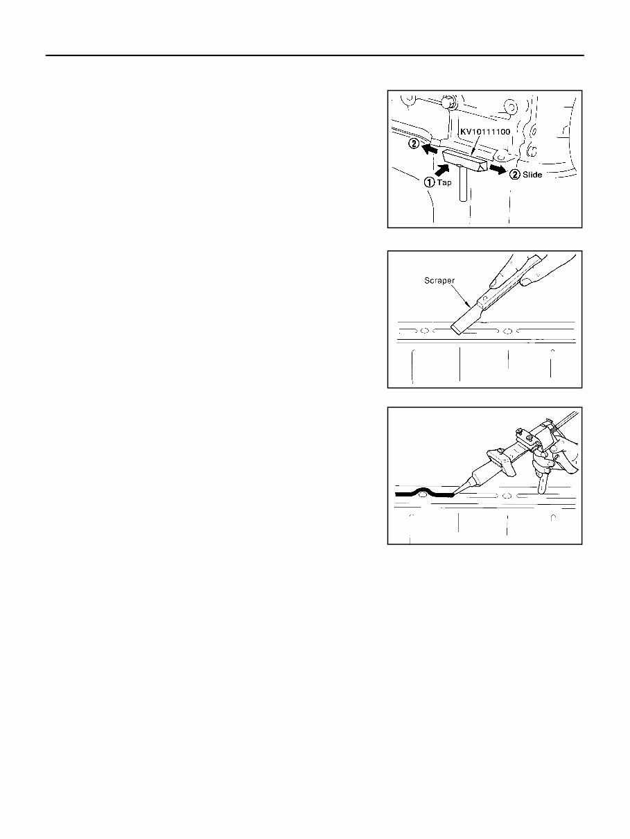
EM-6 [KA24DE] PRECAUTIONS Precautions for Liquid Gasket EBS007JY REMOVAL OF LIQUID GASKET SEALING ● After removing the mounting bolts and nuts, disconnect and remove the liquid gasket sealing using a seal cutter. CAUTION: Be careful not to damage the mating surfaces. ● In areas where the cutter is difficult to use, use a plastic hammer to lightly tap the areas where the liquid gasket is applied. CAUTION: If for some unavoidable reason a tool such as a flat-bladed screwdriver is used, be careful not to damage the mating sur- faces. LIQUID GASKET APPLICATION PROCEDURE 1. Using a scraper, remove the old liquid gasket adhering to the gasket application surface and the mating surface. ● Remove the liquid gasket completely from the groove of the gas- ket application surface, mounting bolts, and bolt holes. 2. Wipe the gasket application surface and the mating surface with white gasoline (lighting and heating use) to remove adhering moisture, grease and foreign materials. 3. Attach the liquid gasket to the tube presser. Use Genuine Liquid Gasket or equivalent. 4. Apply the gasket without breaks to the specified location with the specified dimensions. ● If there is a groove for the liquid gasket application, apply the gasket to the groove. ● As for the bolt holes, normally apply the gasket inside the holes. Occasionally, it should be applied outside the holes. Make sure to read the text of service manual. ● Within five minutes of gasket application, install the mating com- ponent. ● If the liquid gasket protrudes, wipe it off immediately. ● Do not retighten after the installation. ● After 30 minutes or more have passed from the installation, fill the engine oil and coolant. CAUTION: If there are specific instructions in the service manual, observe them. PBIC0275E PBIC0003E EMA0622D
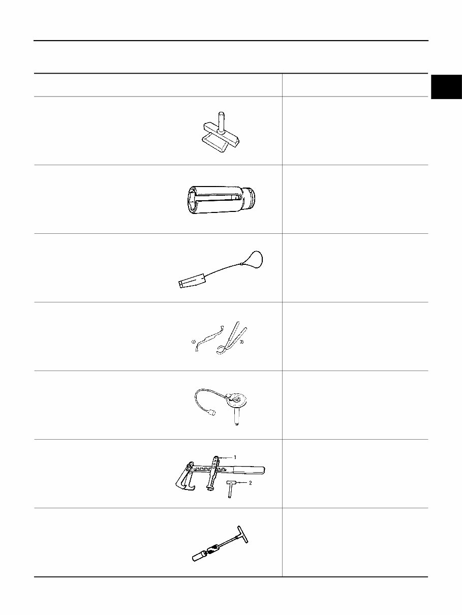
PREPARATION EM-7 [KA24DE] C D E F G H I J K L M A EM PREPARATION PFP:00002 Special Service Tools EBS007JZ Tool number Tool name Description KV10111100 Seal cutter Removing steel oil pan and rear timing chain case KV10117100 Heated oxygen sensor wrench Loosening or tightening heated oxygen sensors with 22 mm (0.87 in) hexagon nut KV10105800 Timing chain stopper Removing and installing idler sproket KV101151S0 Lifter stopper set 1 KV10115120 Lifter stopper 2 KV10115110 Camshaft pliers Changing valve lifter shims KV10112100 Angle wrench Tightening bolts for bearing cap, cylinder head, etc. KV10116200 Valve spring compressor KV10111200 Adapter Disassembling and assembling valve components KV10116100 Valve oil seal puller Removing valve oil seal ZZA0013D ZZA1007D ZZA1006D ZZA0103D ZZA0120D ZZA0993D ZZA0015D
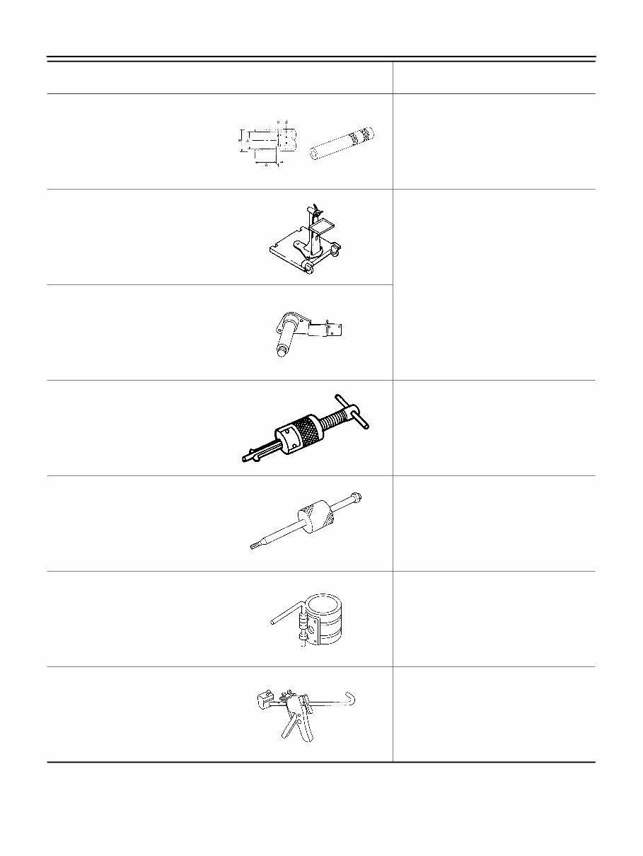
EM-8 [KA24DE] PREPARATION Commercial Service Tools EBS007K0 KV10116300 Valve oil seal drift Installing valve oil seal a: 25 mm (0.98 in) dia. b: 14.4 mm (0.567 in) dia. c: 11.8 mm (0.465 in) dia. d: 10 mm (0.39 in) dia. e: 11 mm (0.43 in) f: 9 mm (0.35 in) ST0501S000 Engine stand assembly Engine overhaul KV10105001 Engine attachment ST16610001 Pilot bushing puller Removing crankshaft pilot bushing (M/T model only) KV10114700 Main bearing cap remover EM03470000 Piston ring compressor Installing piston assembly into cylinder bore WS39930000 Tube presser Pressing the tube of liquid gasket Tool number Tool name Description NT602 ZZA0022D ZZA1061D ZZA0046D ZZA0023D S-NT044 S-NT052
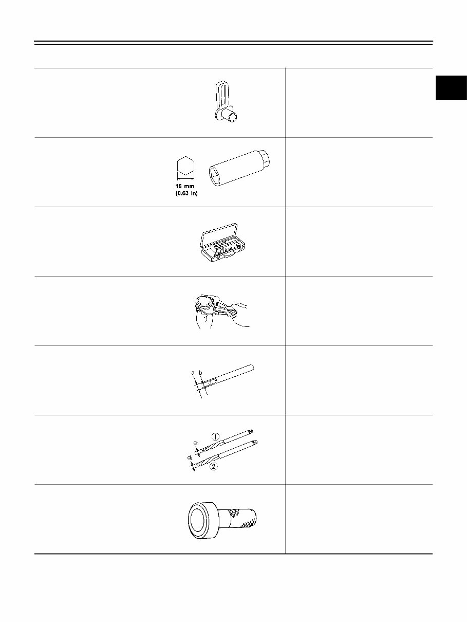
PREPARATION EM-9 [KA24DE] C D E F G H I J K L M A EM Tool number Tool name Description Quick connector release Removing fuel tube quick connectors in engine room (Available in SEC. 164 of PARTS CATALOG: Part No. 16441 6N210) Spark plug wrench Removing and installing spark plug Valve seat cutter set Finishing valve seat dimensions Piston ring expander Removing and installing piston ring Valve guide drift Removing and installing valve guide Intake & Exhaust: a: 109.5 mm (0.413 in) dia. b: 6.6 mm (0.260 in) dia. Valve guide reamer 1: Reaming valve guide inner hole 2: Reaming hole for oversize valve guide Intake & Exhaust: d1 : 7.0 mm (0.276 in) dia. d2 : 11.175 mm (0.440 in) dia. Rear oil seal drift Installing rear oil seal PBIC0198E S-NT047 S-NT048 S-NT030 S-NT015 S-NT016 ZZA0025D
Nissan KA24DE/ZD30DD Engines Service & Repair Manual
Models covered:
Nissan KA24DE
Nissan ZD30DD
Vehicles with KA24DE engine:
Nissan 240SX (1989-1998)
Nissan Altima (1993-2001)
Nissan Frontier (1998-2004)
Nissan Xterra (2000-2004)
Nissan Serena (1993-2001)
Nissan Bluebird U14 (1996-1998)
Nissan Avenir W11 (1998-2000)
Nissan R'nessa N30 (1997-2001)
Vehicles with ZD30DD engine:
Nissan Caravan (1999-2012)
Nissan Elgrand (1999-2002)
Nissan Navara (1999-2004)
Nissan Pathfinder (1995-2004)
Nissan Patrol (1999-2013)
Nissan Terrano II (1999-2006)
This service and repair manual for Nissan KA24DE and ZD30DD engines provides detailed technical instructions for maintenance, troubleshooting, and mechanical repairs. Designed to meet factory specifications, it includes step-by-step procedures, factory-recommended service intervals, and diagnostic techniques to ensure efficient engine performance.
The manual covers essential systems, including the fuel injection system, cooling system, lubrication, ignition, and timing. It also features factory-authorized wiring diagrams, torque settings, and exploded parts views, making it ideal for both routine maintenance and more complex repairs on KA24DE and ZD30DD engines.
Available in digital format, this manual can be accessed on computers and mobile devices, offering convenience for both workshop and field use. Whether you’re a professional mechanic or a hands-on owner, this comprehensive guide is a valuable resource for keeping your Nissan KA24DE or ZD30DD engine running reliably in demanding conditions.
Printable: Yes Language: English Compatibility: Pretty much any electronic device, incl. PC & Mac computers, Android and Apple smartphones & tablet, etc. Requirements: Adobe Reader (free)
Reviews
Q&A
Recently Viewed
5,521,897Happy Clients
2,594,462eManuals
1,120,453Trusted Sellers
15Years in Business
Price:
Actual Price:
Nissan KA24DE/ZD30DD Engines Service & Repair Manual