


ENGINE MECHANICAL
SECTION EM
CONTENTS
ZD
PRECAUTIONS ...............................................................3
Parts Requiring Angular Tightening .............................3
Liquid Gasket Application Procedure ..........................3
PREPARATION ................................................................4
Special Service Tools ..................................................4
Commercial Service Tools ...........................................6
NOISE, VIBRATION AND HARSHNESS (NVH)
TROUBLESHOOTING .....................................................8
NVH Troubleshooting Chart - Engine Noise ...............9
MEASUREMENT OF COMPRESSION PRESSURE ....10
INTERCOOLER ............................................................. 11
Removal and Installation ........................................... 11
INTAKE MANIFOLD ......................................................12
Removal and Installation ...........................................12
Inspection...................................................................13
CATALYST AND TURBOCHARGER ............................14
Removal and Installation ...........................................14
Inspection...................................................................15
EXHAUST MANIFOLD ..................................................18
Removal and Installation ...........................................18
Inspection...................................................................19
ROCKER COVER ..........................................................20
Removal and Installation ...........................................20
OIL PAN & OIL STRAINER...........................................22
Removal and Installation ...........................................22
VACUUM PUMP ............................................................24
Removal and Installation ...........................................24
TIMING CHAIN ..............................................................26
Removal and Installation ...........................................26
Removal .....................................................................26
Installation ..................................................................28
CAMSHAFT ...................................................................30
Removal and Installation ...........................................30
Removal .....................................................................30
Inspection...................................................................31
Installation ..................................................................33
VALVE CLEARANCE INSPECTIONS AND
ADJUSTMENTS.............................................................35
Inspection...................................................................35
Adjustments ...............................................................36
TIMING GEAR ...............................................................38
Removal and Installation ...........................................38
Removal .....................................................................39
Inspection...................................................................41
Installation ..................................................................46
OIL SEAL REPLACEMENT ..........................................50
CYLINDER HEAD..........................................................52
Removal and Installation ...........................................52
Removal .....................................................................52
Inspection...................................................................53
Installation ..................................................................54
Disassembly...............................................................57
Inspection...................................................................58
Assembly ...................................................................61
ENGINE REMOVAL .......................................................63
Precautions ................................................................63
Removal .....................................................................63
Installation ..................................................................65
Inspection...................................................................65
CYLINDER BLOCK .......................................................66
Selection Procedure for Selective Part
Combination ...............................................................67
Disassembly...............................................................67
Inspection...................................................................71
Assembly ...................................................................80
SERVICE DATA AND SPECIFICATIONS (SDS) ..........84
General Specifications ...............................................84
Compression Pressure ..............................................84
Cylinder Head ............................................................84
Valve ..........................................................................84
Valve Seat ..................................................................87
Camshaft and Camshaft Bearing ..............................89
Cylinder Block ............................................................90
Piston, Piston Ring and Piston Pin ...........................90

Connecting Rod .........................................................91
Crankshaft..................................................................92
Available Main Bearing ..............................................92
Available Connecting Rod Bearing............................93
Miscellaneous Components.......................................94
TD27Ti
PRECAUTIONS .............................................................95
Parts Requiring Angular Tightening ...........................95
Liquid Gasket Application Procedure ........................95
PREPARATION ..............................................................96
Special Service Tools ................................................96
Commercial Service Tools .........................................99
ENGINE COMPONENTS - Outer Parts .....................100
ENGINE COMPONENTS - Internal Parts ..................102
COMPRESSION PRESSURE......................................103
Measurement of Compression Pressure .................103
CYLINDER HEAD........................................................104
Removal ...................................................................105
Disassembly.............................................................106
Inspection.................................................................107
Assembly ................................................................. 113
Installation ................................................................ 114
OIL SEAL REPLACEMENT ........................................ 117
TURBOCHARGER....................................................... 119
Removal and Installation ......................................... 119
Inspection................................................................. 119
ENGINE REMOVAL .....................................................123
ENGINE OVERHAUL ..................................................125
Disassembly.............................................................125
Inspection.................................................................127
Assembly .................................................................138
SERVICE DATA AND SPECIFICATIONS (SDS) ........143
General Specifications .............................................143
Inspection and Adjustment ......................................144
CONTENTS (Cont’d)
EM-2
Parts Requiring Angular Tightening
I Use an angle wrench for the final tightening of the cylinder head
bolts.
I Do not use a torque value for final tightening.
I The torque value for these parts are for a preliminary step.
I Ensure thread and seat surfaces are clean and coated with
engine oil.
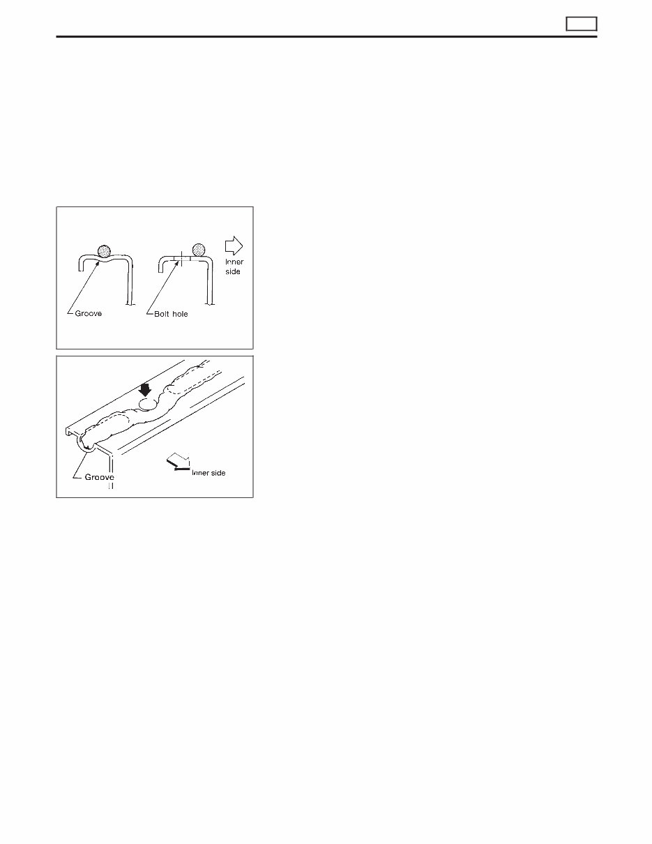
Liquid Gasket Application Procedure
1. Use a scraper to remove old liquid gasket from mating
surfaces and grooves. Also, completely clean any oil from
these areas.
2. Apply a continuous bead of liquid gasket to mating sur-
faces. (Use Genuine Liquid Gasket or equivalent.)
I Be sure liquid gasket diameter is as specified.
3. Apply liquid gasket around the inner side of bolt holes
(unless otherwise specified).
4. Assembly should be done within 5 minutes after coating.
5. Wait at least 30 minutes before refilling engine oil and
engine coolant.
SEM164F
AEM080
PRECAUTIONS
ZD
EM-3
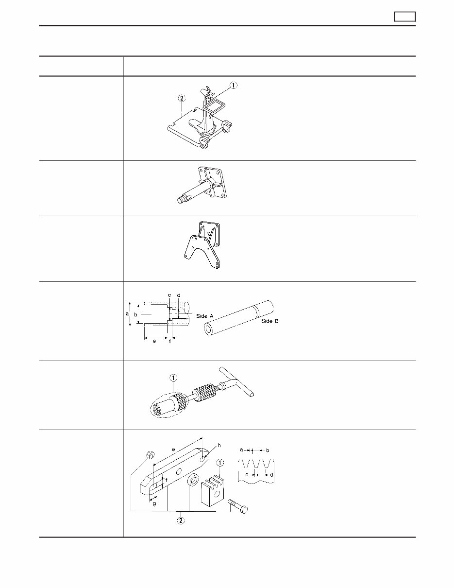
Special Service Tools
Tool number
Tool name
Description
ST0501S000
Engine stand assembly
q 1 ST05011000
Engine stand
q 2 ST05012000
Base
NT042
Disassembling and assembling
KV10106500
Engine stand shaft
NT028
KV11106101
Engine sub-attachment
NT819
KV10115600
Valve oil seal drift
NT603
Installing valve oil seal
Use side A.
Side A
a: 20 (0.79) dia.
b: 13 (0.51) dia.
c: 10.3 (0.406) dia.
d: 8 (0.31) dia.
e: 10.7 (0.421)
f: 5 (0.20)
Unit: mm (in)
KV10107902
Valve oil seal puller
q 1 KV10116100
Valve oil seal puller
adapter
NT605
Removing valve oil seal
KV101056S0
Ring gear stopper
q 1 KV10105630
Adapter
q 2 KV10105610
Plate
NT617
Preventing crankshaft from rotating
a: 3 (0.12)
b: 6.4 (0.252)
c: 2.8 (0.110)
d: 6.6 (0.260)
e: 107 (4.21)
f: 14 (0.55)
g: 20 (0.79)
h: 14 (0.55) dia.
Unit: mm (in)
PREPARATION
ZD
EM-4
Tool number
Tool name
Description
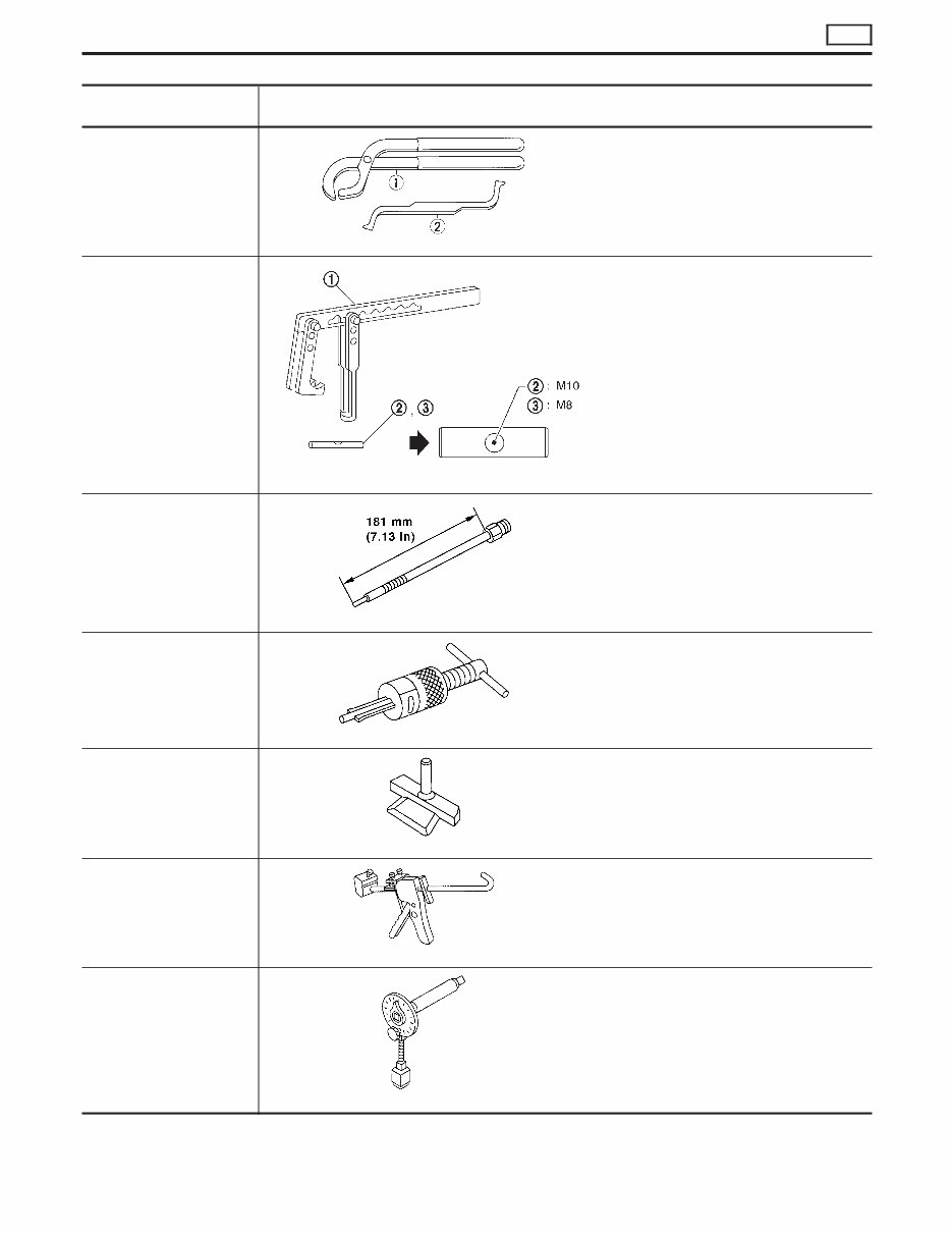
KV101151S0
Lifter stopper set
q 1 KV10115110
Camshaft pliers
q 2 KV10115120
Lifter stopper
NT041
Changing shims
KV101092S0
Valve spring compressor
q 1 KV10109210
Compressor
q 2 KV10109220
Adapter
NT718
Disassembling and assembling valve compo-
nents
ED19600620
Compression gauge adapter
NT820
Checking compression pressure
ST16610000
Pilot bushing puller
NT045
Removing crankshaft pilot bushing
KV10111100
Seal cutter
NT046
Removing steel oil pan and rear timing chain
case
WS39930000
Tube presser
NT052
Pressing the tube of liquid gasket
KV10112100
Angle wrench
NT014
Tightening bolts for bearing cap, cylinder head,
etc.
PREPARATION
ZD
Special Service Tools (Cont’d)
EM-5
Tool number
Tool name
Description
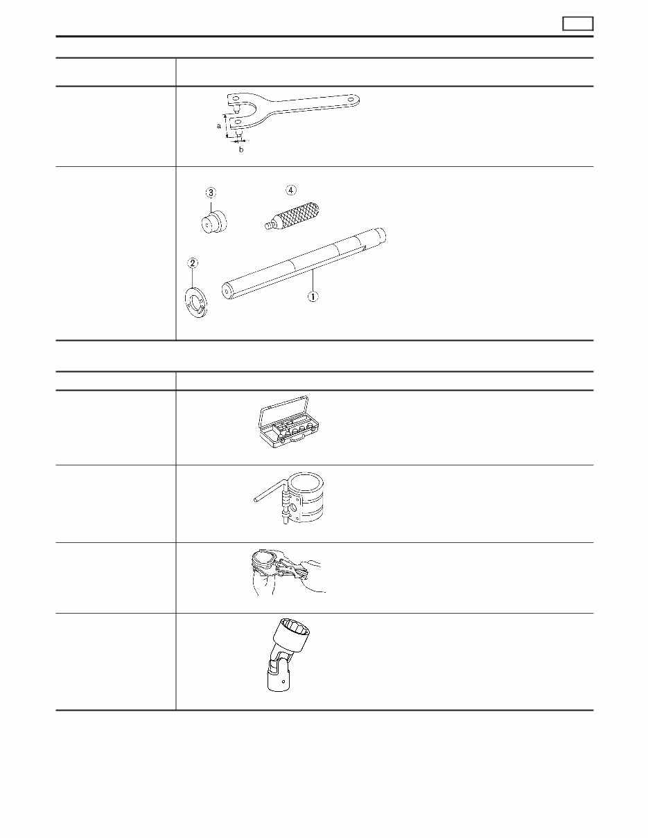
KV10109300
Pulley holder
NT628
a: 68 mm (2.68 in)
b: 8 mm (0.31 in) dia.
KV111045S1
Balancer shaft bearing
replacer set
q 1 KV11104510
Replacer bar
q 2 KV11104521
Guide plate
q 3 KV11104530
Adapter
(Front bearing)
q 4 ST15243000
Drift
NT258
Removing and installing balancer shaft bearing
Commercial Service Tools
Tool name Description
Valve seat cutter set
NT048
Finishing valve seat dimensions
Piston ring compressor
NT044
Installing piston assembly into cylinder bore
Piston ring expander
NT030
Removing and installing piston ring
Standard Universal
NT808
Removing and installing transmission mount
PREPARATION
ZD
Special Service Tools (Cont’d)
EM-6
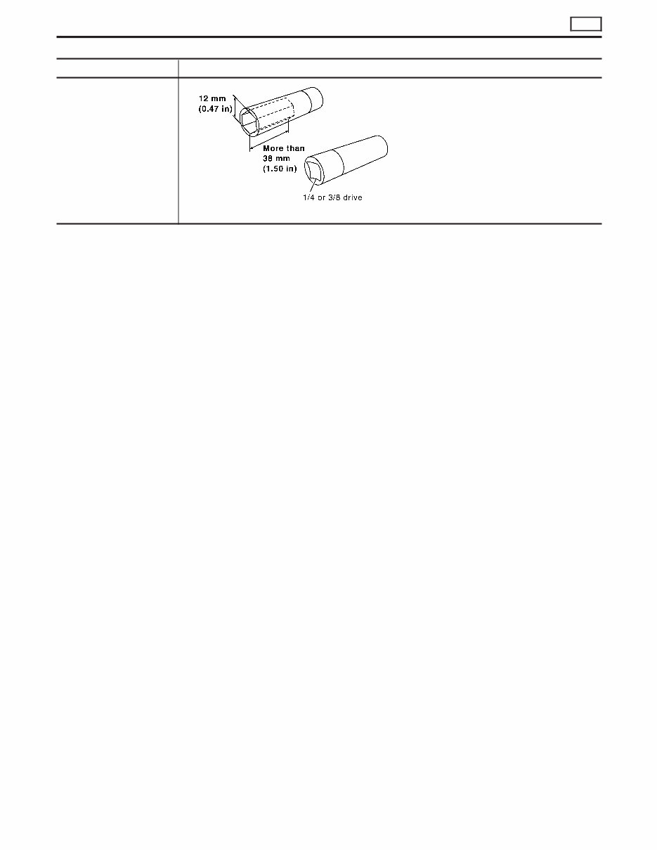
Tool name Description
Deep socket (12 mm)
NT821
Removing and installing glow plugs
PREPARATION
ZD
Commercial Service Tools (Cont’d)
EM-7
SEM290G
NOISE, VIBRATION AND HARSHNESS (NVH) TROUBLESHOOTING
ZD
EM-8

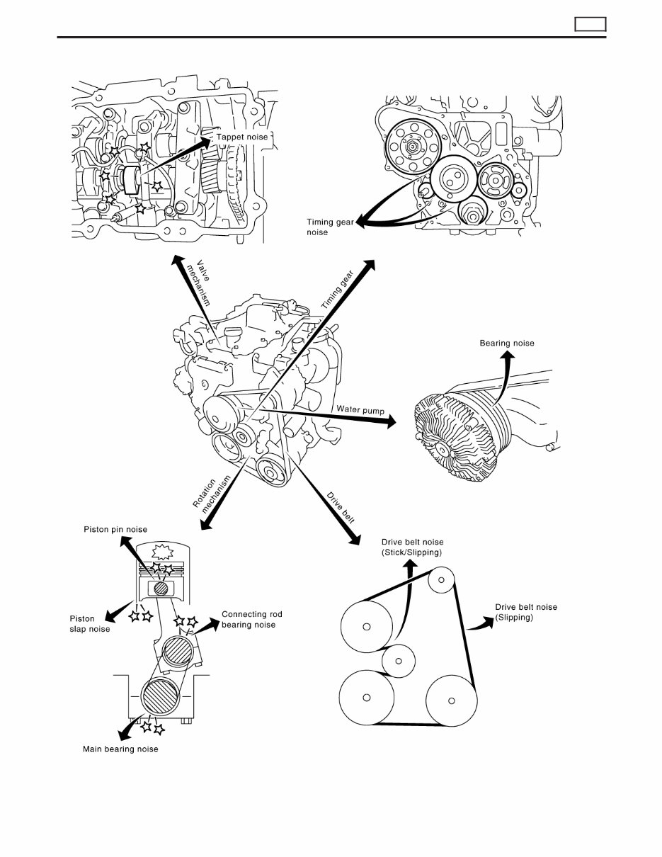
NVH Troubleshooting Chart — Engine Noise
Use the chart below to help you find the cause of the symptom.
1. Locate the area where noise occurs.
2. Confirm the type of noise.
3. Specify the operating condition of engine.
4. Check specified noise source.
If necessary, repair or replace these parts.
Location of
noise
Type of
noise
Operating condition of engine
Source of
noise
Check item
Reference
page
Before
warm-up
After
warm-up
When
starting
When
idling
When
racing
While
driving
Top of
engine
Rocker
cover
Cylinder
head
Ticking or
clicking
C A — A B —
Tappet
noise
Valve clearance
MA section
(“Adjusting
Intake &
Exhaust
Valve
Clearance”,
“ENGINE
MAINTE-
NANCE”)
Rattle C A — A B C
Camshaft
bearing
noise
Camshaft bushing clearance
Camshaft runout
EM-31, 31
Crankshaft
pulley
Cylinder
block (Side
of engine)
Oil pan
Slap or
knock
— A — B B —
Piston pin
noise
Piston and piston pin clear-
ance
Connecting rod bushing
clearance
EM-71, 73
Slap or rap A — — B B A
Piston slap
noise
Piston-to-bore clearance
Piston ring side clearance
Piston ring end gap
Connecting rod bend and
torsion
EM-75, 72,
72, 73
Knock A B C B B B
Connecting
rod bearing
noise
Connecting rod bushing
clearance (Small end)
Connecting rod bearing
clearance (Big end)
EM-73, 77
Knock A B — A B C
Main bear-
ing noise
Main bearing oil clearance
Crankshaft runout
EM-78, 76
Front of
engine
Timing gear
cover
Tapping or
ticking
A A — B B B
Timing gear
noise
Timing gear backlash EM-41
Front of
engine
Squeaking
or fizzing
A B — B — C
Other drive
belts (Stick-
ing or slip-
ping)
Drive belts deflection
MA section
(“Checking
Drive Belts”,
“ENGINE
MAINTE-
NANCE”)
Creaking A B A B A B
Other drive
belts (Slip-
ping)
Idler pulley bearing operation
Squall
Creak
A B — B A B
Water pump
bearing
noise
Water pump bearing opera-
tion
LC section
(“Water
Pump
Inspection”,
“ENGINE
COOLING
SYSTEM”)
A: Closely related B: Related C: Sometimes related —: Not related
NOISE, VIBRATION AND HARSHNESS (NVH) TROUBLESHOOTING
ZD
EM-9
1. Warm up engine.
2. Turn ignition switch OFF.
3. Using CONSULT-II, make sure no error codes are indicated for
self-diagnosis items. Refer to EC section, “Fuel Pressure
Release”.
I Do not disconnect CONSULT-II until the end of this operation;
it will be used to check engine rpm and for error detection at
the end of this operation.
4. Disconnect the negative battery terminal.
5. Remove the following parts.
I Intercooler
I Throttle body
I Rocker cover
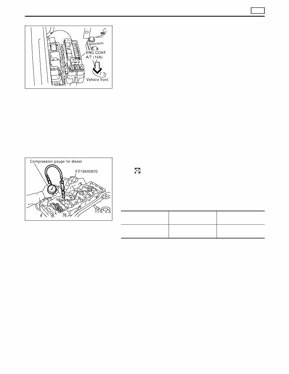
6. To prevent fuel from being injected during inspection, remove
fuel injection pump fuse [ENG CONT A/T (15A)] from fuse box
on the right side of engine compartment.
7. Remove glow plugs from all the cylinders.
I Before removal, clean the surrounding area to prevent
entry of any foreign materials into the engine.
I Carefully remove glow plugs to prevent any damage or
breakage.
I Handle with care to avoid applying any shock to glow
plugs.
8. Install adapter (SST) to installation holes of glow plugs and
connect compression gauge for diesel engine.
: 15 - 19 N⋅m (1.5 - 2.0 kg-m, 11 - 14 ft-lb)
9. Connect battery negative terminal.
10. Set the ignition switch to “START” and crank. When gauge
pointer stabilizes, read compression pressure and engine rpm.
Repeat the above steps for each cylinder.
I Always use a fully-charged battery to obtain specified
engine speed.
Unit: kPa (bar, kg/cm
2
, psi)/rpm
Standard Minimum
Difference limit between
cylinders
2,942 (29.42, 30.0, 427)/
200
2,452 (24.52, 25.0, 356)/
200
294 (2.94, 3.0, 43)/200
I When engine rpm is out of the specified range, check the spe-
cific gravity of battery liquid. Measure again under corrected
conditions.
I If engine rpm exceeds the limit, check valve clearance and
combustion chamber components (valves, valve seats, cylinder
head gaskets, piston rings, pistons, cylinder bores, cylinder
block upper and lower surfaces) and measure again.
11. Complete this operation as follows:
a. Turn the ignition switch to “OFF”.
b. Disconnect battery negative terminal.
c. Replace glow plug oil seals and install glow plugs.
d. Install fuel injection pump fuse [ENG CONT A/T (15A)].
e. Connect battery negative terminal.
f. Using CONSULT-II make sure no error code is indicated for
items of self-diagnosis. Refer to EC section, “Trouble Diagno-
sis — Index”.
YEM039
SEM334G
MEASUREMENT OF COMPRESSION PRESSURE
ZD
EM-10
You're Reading a Preview
What's Included?
Fast Download Speeds
Online & Offline Access
Access PDF Contents & Bookmarks
Full Search Facility
Print one or all pages of your manual
$36.99
Nissan ZD30 / TD27Ti Engines Service & Repair Manual
Viewed 14 Times Today

What's Included?
Fast Download Speeds
Online & Offline Access
Access PDF Contents & Bookmarks
Full Search Facility
Print one or all pages of your manual
$36.99

Secure transaction
What's Included?
Fast Download Speeds
Online & Offline Access
Access PDF Contents & Bookmarks
Full Search Facility
Print one or all pages of your manual
Description
Get the complete engine workshop manual for the Navara, Patrol & Terrano featuring the ZD30 or TD27Ti engine. This manual is an essential resource for both professional mechanics and DIY enthusiasts.
- Sections in this manual include:
- ZD30
- PRECAUTIONS
- Parts Requiring Angular Tightening
- Liquid Gasket Application Procedure
- PREPARATION
- Special Service Tools
- Commercial Service Tools
- NOISE, VIBRATION AND HARSHNESS (NVH)
- TROUBLESHOOTING
- NVH Troubleshooting Chart - Engine Noise
- MEASUREMENT OF COMPRESSION PRESSURE
- INTERCOOLER
- Removal and Installation
- INTAKE MANIFOLD
- Removal and Installation
- Inspection
- CATALYST AND TURBOCHARGER
- Removal and Installation
- Inspection
- EXHAUST MANIFOLD
- Removal and Installation
- Inspection
- ROCKER COVER
- Removal and Installation
- OIL PAN & OIL STRAINER
- Removal and Installation
- VACUUM PUMP
- Removal and Installation
- TIMING CHAIN
- Removal and Installation
- Removal
- Installation
- CAMSHAFT
- Removal and Installation
- Removal
- Inspection
- Installation
- Connecting Rod
- Crankshaft
- Available Main Bearing
- Available Connecting Rod Bearing
- Miscellaneous Components
- VALVE CLEARANCE INSPECTIONS AND ADJUSTMENTS
- Inspection
- Adjustments
- TIMING GEAR
- Removal and Installation
- Removal
- Inspection
- Installation
- OIL SEAL REPLACEMENT
- CYLINDER HEAD
- Removal and Installation
- Removal
- Inspection
- Installation
- Disassembly
- Inspection
- Assembly
- ENGINE REMOVAL
- Precautions
- Removal
- Installation
- Inspection
- CYLINDER BLOCK
- Selection Procedure for Selective Part Combination
- Disassembly
- Inspection
- Assembly
- SERVICE DATA AND SPECIFICATIONS (SDS)
- General Specifications
- Compression Pressure
- Cylinder Head
- Valve
- Valve Seat
- Camshaft and Camshaft Bearing
- Cylinder Block
- Piston, Piston Ring and Piston Pin
- TD27Ti
- PRECAUTIONS
- Parts Requiring Angular Tightening
- Liquid Gasket Application Procedure
- PREPARATION
- Special Service Tools
- Commercial Service Tools
- ENGINE COMPONENTS - Outer Parts
- ENGINE COMPONENTS - Internal Parts
- COMPRESSION PRESSURE
- Measurement of Compression Pressure
- CYLINDER HEAD
- Removal
- Disassembly
- Inspection
- Assembly
- Installation
- OIL SEAL REPLACEMENT
- TURBOCHARGER
- Removal and Installation
- Inspection
- ENGINE REMOVAL
- ENGINE OVERHAUL
- Disassembly
- Inspection
- Assembly
- SERVICE DATA AND SPECIFICATIONS (SDS)
- General Specifications
- Inspection and Adjustment


