GENERAL INFORMATION 11B-0-3 ................................................... 1. SPECIFICATIONS 11B-1-1 ....................................................... SERVICE SPECIFICATIONS 11B-1-1 ............................................ TORQUE SPECIFICATIONS 11B-1-4 ............................................ SEALANT 11B-1-8 ........................................................... 2. SPECIAL TOOLS 11B-2-1 ....................................................... 3. GENERATOR ASSEMBLY 11B-3-1 ............................................... 4. GLOW PLUG 11B-4-1 ........................................................... 5. COOLING FAN, V-BELT AND WATER PUMP 11B-5-1 ............................... 6. WATER HOSES AND PIPES 11B-6-1 .............................................. 7. THERMOSTAT 11B-7-1 .......................................................... 8. EGR VALVE ASSEMBLY 11B-8-1 ................................................. 9. INTAKE MANIFOLD 11B-9-1 ..................................................... 10. TURBOCHARGER ASSEMBLY 11B-10-1 ......................................... 11. EXHAUST MANIFOLD 11B-11-1 .................................................. 12. INJECTION PUMP ASSEMBLY 11B-12-1 ......................................... 13. INJECTION PUMP GEAR 11B-13-1 .............................................. 14. ROCKER COVER, CAMSHAFT HOLDER ASSEMBLY AND CAMSHAFT 11B-14-1 .... 15. INJECTION NOZZLE 11B-15-1 .................................................. 16. CYLINDER HEAD AND VALVE MECHANISM 11B-16-1 ............................. 17. VACUUM PUMP 11B-17-1 ...................................................... 18. TIMING GEAR CASE 11B-18-1 .................................................. 19. TIMING GEAR AND BALANCE SHAFT 11B-19-1 .................................. 20. OIL PUMP 11B-20-1 ............................................................ 21. OIL COOLER AND OIL FILTER 11B-21-1 ......................................... 22. OIL PAN, OIL STRAINER AND OIL JET 11B-22-1 .................................. 23. PISTON AND CONNECTING ROD 11B-23-1 ...................................... 24. DRIVE PLATE 11B-24-1 ........................................................ 25. CRANK SHAFT AND CRANK CASE 11B-25-1 .................................... 26. BALANCE SHAFT BUSH 11B-26-1 .............................................. 11B-0-1 ENGINE 4M41 CONTENTS PWEE9409-D E Feb. 2000 Mitsubishi Motors Corporation Added
11B-0-2 NOTES PWEE9409-D E Feb. 2000 Mitsubishi Motors Corporation Added
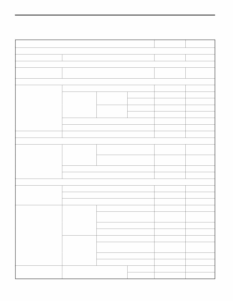
4M41 ENGINE - General Information 11B-0-3 GENERAL INFORMATION Descriptions Specifications Total displacement dm 3 3200 No. and arrangement of cylinders 4 in-line Combustion chamber Direct injection No. of intake/exhaust valves (per cylinder) 2 each Valve mechanism Double overhead camshaft, 4-valve Cylinder bore x stroke mm 98.5 x 10⁵ Compression ratio 17 Supercharger Turbo-charging type Intercooler Air-cooling type Fuel supply Distributor type electronically controlled fuel injection pump PWEE9409-D E Feb. 2000 Mitsubishi Motors Corporation Added
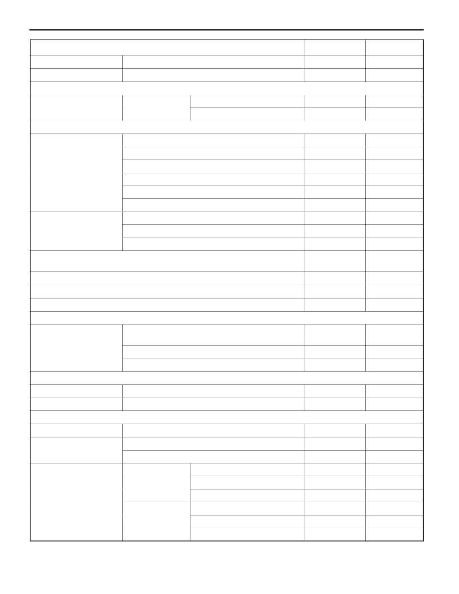
4M41 ENGINE - Specifications 11B-1-2 Descriptions Limit Standard Valve seat Seat width 1.8 - 2.2 2.8 Cylinder head Bottom surface distortion Less than 0.05 0.2 Vacuum pump Vacuum pump Performance Attained degree of vacuum 93 kPa or more - Pump speed 1500 r/min - Timing gears and balance shafts Backlash between gears Balance shaft gear RH and oil pump gear 0.04 - 0.19 0.3 Oil pump gear and crankshaft gear 0.04 - 0.18 0.3 Crankshaft gear and idler gear 0.04 - 0.18 0.3 Idler gear and idler gear LH 0.04 - 0.19 0.3 Idler gear LH and balance shaft gear LH 0.04 - 0.22 0.4 Idler gear and injection pump gear 0.04 - 0.21 0.4 End play Balance shaft LH, RH 0.09 - 0.24 0.3 Idler gear/sprocket assembly 0.05 - 0.20 0.3 Idler gear LH assembly 0.05 - 0.20 0.3 Timing chain elongation (minimum distance between chain spans facing each other when pressing on tensioner lever) 16.5 9 Tension lever-to-tension lever shaft clearance 0.06 - 0.18 0.3 Idler gear bush LH-to-idler shaft clearance 0.02 - 0.05 0.1 Idler sprocket bush-to-idler shaft clearance 0.02 - 0.06 0.1 Oil pump Oil pump Driven gear shaft-to-oil pump case and cover clearance 0.03 - 0.05 0.15 Side clearance 0.05 - 0.10 0.15 Tip clearance 0.15 - 0.26 0.27 Oil cooler and oil filter Bypass valve spring Valve opening pressure kPa 490 – 30 - Regulator valve spring Valve opening pressure kPa 620 – 30 - Piston and connecting rod assembly Piston Protrusion -0.20 - -0.30 - Piston pin Piston pin-to-connecting rod bush clearance 0.03 - 0.05 0.1 Piston pin-to-piston clearance 0.007 - 0.021 0.05 Piston ring Ring-to-ring No.1 compression ring 0.03 - 0.08 0.15 groove clearance No.2 compression ring 0.07 - 0.10 0.15 Oil ring 0.03 - 0.06 0.15 End gap No.1 compression ring 0.3 - 0.45 0.8 No.2 compression ring 0.4 - 0.55 0.8 Oil ring 0.3 - 0.5 0.8 PWEE9409-D E Feb. 2000 Mitsubishi Motors Corporation Added
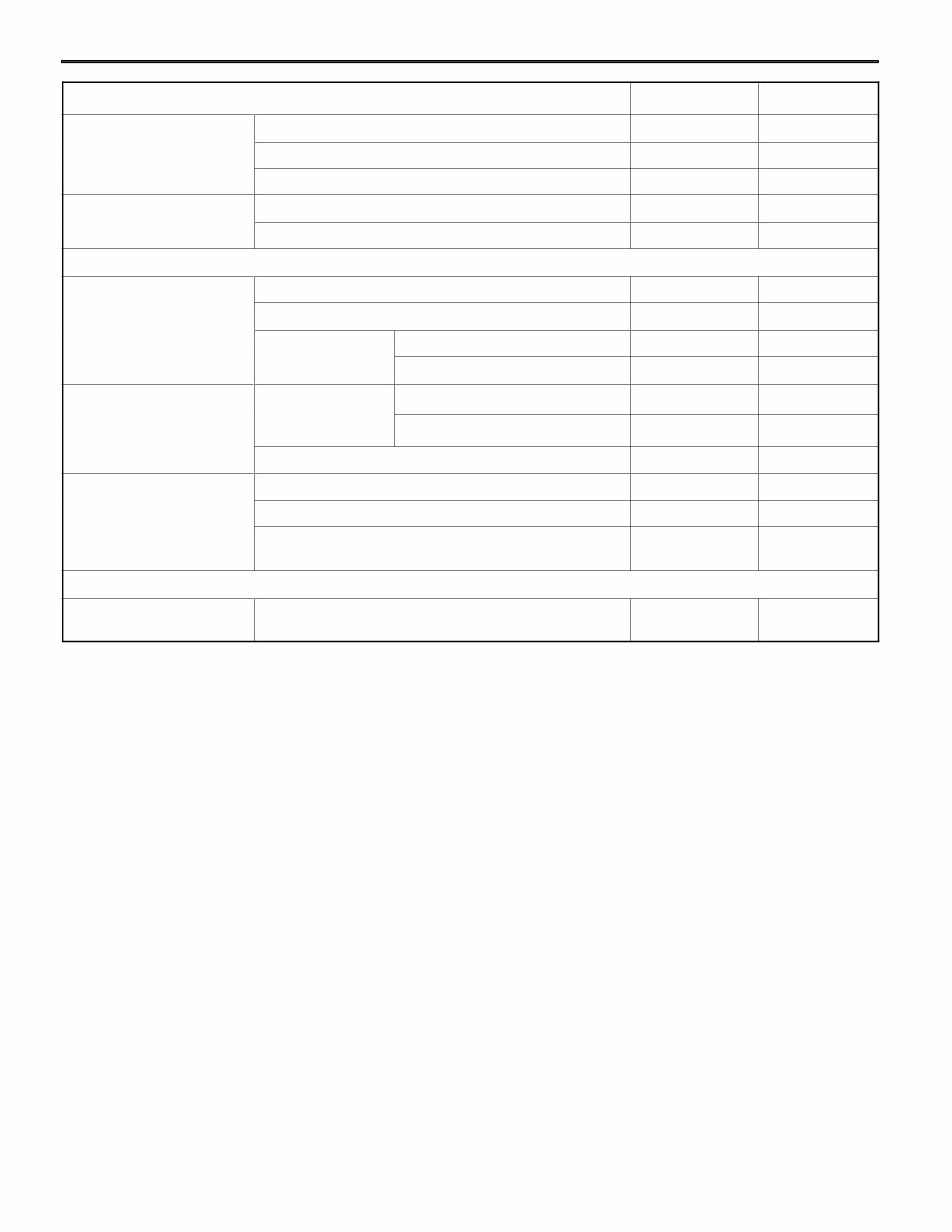
4M41 ENGINE - Specifications 11B-1-3 Descriptions Limit Standard Connecting rod End play 0.15 - 0.45 0.6 Bend - 0.05 Twist - 0.1 Connecting rod bearing Oil clearance 0.03 - 0.05 0.1 Free span - 58.8 max. Crankshaft and crankcase Crankshaft End play 0.10 - 0.28 0.4 Bend Less than 0.02 0.05 Pin and journal Out-of-roundness Less than 0.01 - Conicity Less than 0.006 - Main bearing Main bearing-to- No.1, 2, 4 and 5 journal 0.04 - 0.06 0.1 crankshaft clear- ance No.3 journal 0.06 - 0.08 0.1 Free span - 73.16 max. Upper crankcase Upper surface distortion Less than 0.05 0.1 Cylinder I.D. 98.5 - 98.53 98.75 Piston and connecting rod assembly-to-upper crankcase cylinder clearance 0.04 - 0.05 - Balance shaft bush Balance shaft Clearance between balance shaft and balance shaft bush 0.06 - 0.11 0.16 PWEE9409-D E Feb. 2000 Mitsubishi Motors Corporation Added
Complete Service Repair Manual for MITSUBISHI 4M41 ENGINE is an invaluable resource for the treatment and repair of the engine. This manual includes a comprehensive table of contents covering general information, specifications, service specifications, torque specifications, sealant, special tools, and detailed assembly instructions for various engine components.
Generator Assembly
Glow Plug
Cooling Fan, V-Belt, and Water Pump
Water Hoses and Pipes
Thermostat
EGR Valve Assembly
Intake Manifold
Turbocharger Assembly
Exhaust Manifold
Injection Pump Assembly
Injection Pump Gear
Rocker Cover, Camshaft Holder Assembly, and Camshaft
Injection Nozzle
Cylinder Head and Valve Mechanism
Vacuum Pump
Timing Gear Case
Timing Gear and Balance Shaft
Oil Pump
Oil Cooler and Oil Filter
Oil Pan, Oil Strainer, and Oil Jet
Piston and Connecting Rod
Drive Plate
Crank Shaft and Crank Case
Balance Shaft Bush
This manual is designed for both professional mechanics and DIY enthusiasts. It is available in English format and is compatible with all versions of Windows and Mac. The manual contains numerous pictures and diagrams, making it easy to follow the step-by-step instructions. Additionally, all pages are printable, allowing for easy access to the required information in the garage or workshop.
By utilizing this manual, individuals can save money by performing their own repairs. There are no shipping costs or waiting for a CD to arrive, as the manual is available for instant download upon completion of payment via a secure payment processor. Major credit/debit cards and PayPal are accepted.