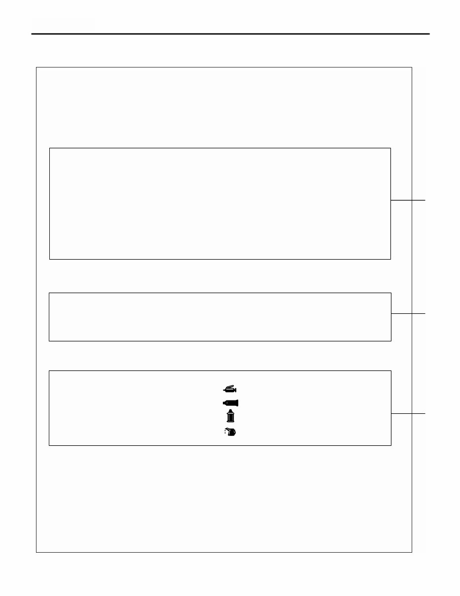
HOW TO USE THIS MANUAL ENGINE OVERHAUL <4G63-Turbo> 11D-2 HOW TO USE THIS MANUAL M1113025100296 This manual describes service procedures performed after removal of the engine from the vehicle. For removal of the engine from the vehicle, installation of the engine in the vehicle, and on-vehicle inspection and service of the engine, please use the separate Workshop Manuals prepared for the vehicle. (1) A component part drawing is shown at the beginning of each section to enable the technician to ascertain the installed con- dition of the component parts. (2) Service steps are indicated by means of numbers in the component part drawing. Non-reusable parts are indicated as such, and tightening torques are shown. ·Removal steps The numbers of the part names match the numbers in the component part drawing and indicate the removal sequence. ·Installation steps Installation steps are omitted wherever installation can be achieved simply by performing the removal steps in reverse. ·Disassembly steps The numbers of the part names match the numbers in the component part drawing and indicate the disassembly sequence. ·Reassembly steps Reassembly steps are omitted wherever reassembly can be achieved simply by performing the disassembly steps in reverse. HOW TO USE THIS MANUAL How to Read Explanations Scope of Service Explanations Service steps Classification of Service Points Key service points, service standards, and instructions for using special tools are collated as service points and ex- plained in detail. <<A>>: Outward-pointing brackets denote removal service points or disassembly service points. >>A<<: Inward-pointing brackets denote installation service points or reassembly service points. Every location where a lubricant or sealant must be applied or added is indicated using a relevant symbol in the compo- nent part drawing and/or on the page after the component part drawing. Lubricant and Sealant Symbols . . . . . . . . . . Grease . . . . . . . . . . Sealant or form-in-place gasket (FIPG) . . . . . . . . . . Brake fluid . . . . . . . . . . Engine oil or gear oil Only those inspection procedures which use special tools or measuring appliances are described. You must perform general visual inspec- tion and part cleaning whenever necessary although their procedures are not described in this manual. Inspection AK202851
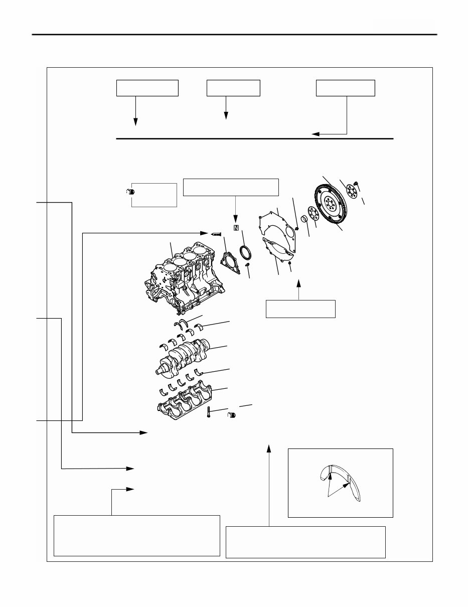
HOW TO USE THIS MANUAL ENGINE OVERHAUL <4G63-Turbo> 11D-3 ENGINE OVERHAUL 11-54 CRANKSHAFT AND CYLINDER BLOCK REMOVAL AND INSTALLATION Section title Page number Procedures and cautions for removal, instal- lation, disassembly, and reassembly are ex- plained under this category of heading. The alphabetical character in this category of heading matches that of the relevant removal steps, installation steps, disassembly steps, or reassembly steps. Denotes non-reusable part. Tightening torque CRANKSHAFT AND CYLINDER BLOCK Removal steps 1. Drive plate bolt 2. Adapter plate 3. Drive plate 4. Crankshaft bushing 5. Rear plate 6. Bellhousing cover >>E<< 7. Oil seal case >>D<< 8. Oil seal >>C<< 9. Bearing cap bolt 10. Bearing cap >>B<< 11. Crankshaft bearing, lower >>A<< 12. Crankshaft >>A<< THRUST BEARING INSTALLATION INSTALLATION SERVICE POINTS AK100786 AB Grooves Group title AK300250 AK204351 AB Apply engine oil to all moving parts before installation. 1 2 3 4 5 6 7 8 9 11 12 13 14 15 16 10 25 ± 2 N·m + 90º to 100º 11 ± 1 N·m 132 ± 5 N·m 9.0 ± 1.0 N·m 11 ± 1 N·m A
GENERAL INFORMATION ENGINE OVERHAUL <4G63-Turbo> 11D-4 GENERAL INFORMATION M1113000100523 VEHICLE AND ENGINE MODELS GENERAL SPECIFICATIONS M1113000200779 Vehicle name Vehicle model Engine model Displacement mL Specification OUTLANDER CU2W 4G63-7 1,997 Double overhead camshaft, 16-valve Item Specification Bore × stroke mm 85 × 88 Displacement mL 1,997 Combustion chamber Pentroof type Number of cylinders 4 Valve mechanism Type Double overhead camshaft Number of intake valves 2 Number of exhaust valves 2 Lash adjusters Hydraulic Rocker arms Roller cam followers Compresssion ratio 9.0 Fuel injection system Electronically controlled multi-point injection (MPI) system Ignition system Electronically controlled two-coil system Generator Alternator (with built-in IC regulator) Starter motor Gear reduction drive type
SERVICE SPECIFICATIONS ENGINE OVERHAUL <4G63-Turbo> 11D-5 SERVICE SPECIFICATIONS M1113000300776 Item Standard value Limit TIMING BELT Auto-tensioner rod extension length (with timing belt installed) mm 3.8 − 4.5 − Auto-tensioner rod extension length (when free) mm 12.0 − Auto-tensioner rod retraction length (when pressed with force of 98 to 196 N) mm Less than 1 − ROCKER ARMS AND CAMSHAFTS Cam height mm 34.91 34.41 CYLINDER HEAD AND VALVES Cylinder head gasket surface warp mm Less than 0.05 0.2 Cylinder head gasket surface grinding limit (including cylinder block grinding amount) mm − 0.2 Cylinder head overall height mm 131.9 − 132.1 − Cylinder head bolt nominal length mm − 99.4 Valve margin mm Intake valves 1.0 0.5 Exhaust valves 1.5 1.0 Valve stem diameter mm 6.6 − Valve face angle 43.5° − 44° − Valve stem-to-guide clearance mm Intake valves 0.02 − 0.05 0.10 Exhaust valves 0.05 − 0.09 0.15 Valve height mm Intake valves 109.5 109.0 Exhaust valves 109.7 109.2 Valve stem projection mm Intake valves 49.2 49.7 Exhaust valves 48.4 48.9 Valve spring free height mm 47.0 46.0 Valve spring load/height N/mm 240/40 − Valve spring squareness 1.5° or smaller 4° Valve face-to-seat contact width mm 0.9 − 1.3 − Valve guide inside diameter mm 6.6 − Valve guide press-in height mm 19.2 − 19.8 − OIL PAN AND OIL PUMP Oil pump gear side clearance mm Drive gear 0.08 − 0.14 − Driven gear 0.06 − 0.12 − Oil cooler by-pass valve mm Dimension (Normal temperature) 34.5 − By-pass hole closing temperature 97 to 103°C 40.0 −
REWOK DIMENSIONS ENGINE OVERHAUL <4G63-Turbo> 11D-6 REWOK DIMENSIONS M1113024300394 Oil pressure at curb idle speed kPa [oil temperature is 75 to 90°] 78 or more − PISTONS AND CONNECTING RODS Piston outside diameter mm 85.0 − Piston ring side clearance in ring groove mm No. 1 0.03 − 0.07 0.1 No. 2 0.02 − 0.06 0.1 Piston ring end gap mm No. 1 0.20 − 0.30 0.8 No. 2 0.30 − 0.45 0.8 Oil ring 0.10 − 0.40 1.0 Piston pin outside diameter mm 22.0 − Piston pin press-in load (at ambient temperature) N 7,350 − 17,100 − Oil clearance at crankshaft pins mm 0.03 − 0.05 0.1 Connecting rod big end thrust clearance mm 0.10 − 0.25 0.4 CRANKSHAFT AND CYLINDER BLOCK Crankshaft end play mm 0.05 − 0.25 0.4 Crankshaft journal diameter mm 57.0 − Crankshaft pin diameter mm 45.0 − Oil clearance at crankshaft journals mm 0.03 − 0.04 0.1 Cylinder block gasket surface warp mm 0.05 0.1 Cylinder block gasket surface grinding limit (including cylinder head grinding amount) mm − 0.2 Cylinder block overall height mm 284 − Cylinder bore diameter mm 85 − Taper of cylinder mm 0.01 or less − Cylinder-to-piston clearance mm 0.02 − 0.04 − Crankshaft bearing cap bolt nominal length mm − 71.1 Item Standard value Limit Item Standard value CYLINDER HEAD AND VALVES Diameter of oversize valve seat ring hole in cylinder head mm Intake 0.3 oversize 35.30 − 35.33 0.6 oversize 35.60 − 35.63 Exhaust 0.3 oversize 33.30 − 33.33 0.6 oversize 33.60 − 33.63 Diameter of oversize valve guide hole in cylinder head mm 0.05 oversize 12.05 − 12.07 0.25 oversize 12.25 − 12.27 0.50 oversize 12.50 − 12.52
TORQUE SPECIFICATIONS ENGINE OVERHAUL <4G63-Turbo> 11D-9 CYLINDER HEAD AND VALVES Cylinder head bolts 78 ± 2 → 0 → 20 ± 2 → + 90° + 90° OIL PUMP CASE AND OIL PAN Drain plug 39 ± 5 Oil filter 14 ± 2 Oil pan bolts 9.0 ± 3.0 Oil screen bolts 19 ± 3 Oil pressure switch 19 ± 3 Oil cooler by-pass valve 54 ± 5 Relief plug 44 ± 5 Oil filter bracket bolts 19 ± 3 Plug cap 23 ± 3 Flange bolt 36 ± 3 Oil pump case bolts 23 ± 3 Oil pump cover bolts 17 ± 1 Oil pump cover screw 10 ± 2 PISTONS AND CONNECTING RODS Connecting rod cap nuts 20 ± 2 → 90° to 94° CRANKSHAFT AND CYLINDER BLOCK Flywheel bolts 132 ± 5 Rear plate bolt 11 ± 1 Bell housing cover bolts 9.0 ± 1.0 Rear oil seal case bolts 11 ± 1 Beam bearing cap bolts 25 ± 2 → 90° to 100° Item N⋅m
SEALANTS ENGINE OVERHAUL <4G63-Turbo> 11D-10 SEALANTS M1113000500703 NOTE: *: Part to be sealed with a form-in-place gasket (FIPG) FORM-IN-PLACE GASKET (FIPG) This engine has several areas where the form-in-place gasket (FIPG) is used for sealing. To ensure that the FIPG fully serves its purpose, it is necessary to observe some precautions when applying it. Bead size, continuity and location are of paramount importance. Too thin a bead could cause leaks. Too thick a bead, on the other hand, could be squeezed out of location, causing blocking or narrowing of fluid passages. To prevent leaks or blocking of passages, therefore, it is absolutely necessary to apply the FIPG evenly without a break, while observing the correct bead size. FIPG hardens as it reacts with the moisture in the atmospheric air, and it is usually used for sealing metallic flange areas. REMOVAL OF FIPG SEALED PARTS Parts sealed with a FIPG can be easily removed without need for the use of a special method. In some cases, however, the FIPG in joints may have to be broken by tapping parts with a mallet or similar tool. You can also tap a flat, thin gasket scraper into the joint to break the FIPG, taking extreme care not to damage the mating surfaces.The oil pan cutter (MD998727) is available as a special tool for removing the oil pan. The tool, however, must not be. CLEANING FIPG APPLICATION SURFACE Thoroughly remove all substances deposited on the FIPG application surface, using a gasket scraper or wire brush. Make sure that the FIPG application surface is flat and smooth. Also make sure that the surface is free from oils, greases and foreign substances. Do not fail to remove old FIPG that may remain in the fastener fitting holes. APPLICATION OF FIPG Applied FIPG bead should be of the specified size and free of any break. FIPG can be wiped away unless it has completely hardened. Install the mating parts in position while the FIPG is still wet (in less than 15 minutes after application). Do not allow FIPG to spread beyond the sealing areas during installation. Avoid operating the engine or letting oils or water come in contact with the sealed area before a time sufficient for FIPG to harden (approximately one hour) has passed. FIPG application method may vary from location to location. Follow the instruction for each particular case described later in this manual. Item Specified sealant Engine support bracket bolts Mitsubishi Genuine Part No.MD970389 or equivalent Semicircular packing 3M ATD No.8660 or equivalent Rocker cover Mitsubishi Genuine Part No. MD970389 or equivalent Engine coolant temperature e gauge unit 3M Nut Locking Part No.4171 or equivalent Engine coolant temperature sensor 3M ATD No.8660 or equivalent Water outlet fitting* Mitsubishi Genuine Part No. MD970389 or equivalent Thermostat housing* Cylinder head (camshaft bearing cap fitting section) 3M ATD No.8660 or equivalent Camshaft position sensor support* Mitsubishi Genuine Part No. MD970389 or equivalent Oil pressure switch 3M ATD No.8660 or equivalent Oil pan* Mitsubishi Genuine Part No. MD970389 or equivalent Rear oil seal case*
This is the complete official full factory service repair manual for the Mitsubishi 4G63 Engine. Whether you're a professional mechanic or a DIY enthusiast, this manual provides detailed information for repair and service. It covers engine identification, general precautions, disassembly and assembly, maintenance check list, special tools, fuel system, troubleshooting, servicing specifications, tightening torques, cooling system, exhaust system, electrical system, alternator, regulator, and wiring diagram.
With step-by-step instructions, detailed substeps, cautions, warnings, and numbered instructions, this manual is designed to guide you through every repair procedure. It also includes illustrations, diagrams, and specifications to help diagnose and correct any problem with the machine's electrical system. The manual is printable without any restriction and is compatible with all PC-based Windows operating systems and Mac. It can be saved to your hard drive and burned to CD-ROM for easy access.
With this Mitsubishi 4G63 Engine Factory Service Repair Manual, you can diagnose, repair, maintain, rebuild, refurbish, or restore your vehicle with ease. It covers all diagnostic and repair procedures in great detail, providing the same information that professional technicians and mechanics have. You can print out the pages you need or the entire manual as a whole, making it a convenient and cost-effective solution for vehicle maintenance.
Product Details:
File Format: .PDF
Language: English
Printable: Yes
Delivery: A download link will appear on the checkout page after payment is complete
Requirements: Adobe Reader
Recently Viewed
5,521,897Happy Clients
2,594,462eManuals
1,120,453Trusted Sellers
15Years in Business
Price:
Actual Price:
Mitsubishi 4G63 Engine Workshop Service Repair Manual