Diesel Engine 62--11161 Rev A WORKSHOP MANUAL for CT2-29-TV (Z482-E2B) Truck / ComfortPro CT3-44-TV (D722-E2B) Truck Beginning With Serial Number 5A0001 R
WORKSHOP MANUAL DIESEL ENGINE CT2-29-TV (Z482-E2B) Truck / ComfortPro CT3-44-TV (D722-E2B) Truck Beginning With Serial Number 5A0001
i 62--11161 TABLE OF CONTENTS PARAGRAPH NUMBER Page TABLE OF CONTENTS i ........................................................................ SAFETY PRECAUTIONS i ................................................................... SPECIFIC WARNING AND CAUTION STATEMENTS i ........................................... General 1--1 ...................................................................................... 1.1 ENGINE IDENTIFICATION 1--1 ............................................................ 1.2 ENGINE SPECIFICATIONS 1--2 ............................................................ 1.2.1 E2B Engine 1--3 ...................................................................... 1.2.2 Cylinder Number 1--3 .................................................................. 1.3 GENERAL PRECAUTIONS 1--3 ............................................................ 1.4 TORQUE SPECIFICATION 1--4 ............................................................ 1.4.1 Torque Specifications For Special Use Screws, Bolts and Nuts 1--4 .......................... 1.4.2 Torque Specifications For General Use Screws, Bolts and Nuts 1--4 .......................... 1.5 TROUBLESHOOTING 1--5 ................................................................ 1.6 SERVICING SPECIFICATIONS 1--8 ........................................................ 1.6.1 Engine Body 1--8 ...................................................................... 1.6.2 Lubricating System 1--11 ................................................................ 1.6.3 Cooling System 1--11 ................................................................... 1.6.4 Fuel System 1--11 ...................................................................... 1.6.5 Electrical System 1--12 .................................................................. 1.7 CHECK AND MAINTENANCE 1--12 .......................................................... 1.7.1 Checking Engine Oil Level 1--12 .......................................................... 1.7.2 Changing Engine Oil 1--12 ............................................................... 1.7.3 Checking Coolant Level 1--12 ............................................................ 1.7.4 Checking Fuel Hose 1--12 ............................................................... 1.7.5 Bleeding Fuel System 1--12 .............................................................. 1.7.6 Valve Clearance 1--13 .................................................................. 1.8 SPECIAL TOOLS 1--14 ..................................................................... 1.8.1 Diesel Engine Compression Tester (Glow Plug) 1--14 ....................................... 1.8.2 Adapter, Kubota 10 mm 1--14 ............................................................ 1.8.3 Tester Injector Nozzle 1--14 .............................................................. 1.8.4 Replacement Bowl, Tester Injector Nozzle 1--14 ............................................ 1.8.5 Adapter, Injector Line 1--14 .............................................................. 1.8.6 Oil Pressure Tester 1--15 ................................................................ 1.8.7 Auxiliary Socket For Fixing Crankshaft Sleeve 1--15 ........................................ 1.8.8 Guage, Belt Tension 1--15 ............................................................... 1.8.9 Tester, Belt Tension 1--15 ................................................................ 1.8.10 Rubber Band 1--15 ..................................................................... 1.8.11 Valve Guide Replacing Tool 1--16 ......................................................... 1.8.12 Bushing Replacing Tools 1--16 ........................................................... 1.8.13 Flywheel Stopper 1--16 .................................................................. 1.8.14 Crankshaft Bearing 1 Replacing Tool 1--17 .................................................
ii 62-11161 PARAGRAPH NUMBER Page ENGINE BODY 2--1 ............................................................................... 2.1 CHECKING AND ADJUSTING 2--1 ......................................................... 2.1.1 Compression Pressure 2--1 ............................................................. 2.1.2 Top Clearance 2--1 .................................................................... 2.2 DISASSEMBLING AND ASSEMBLING 2--2 .................................................. 2.2.1 Draining Coolant 2--2 .................................................................. 2.2.2 Draining and Refilling Engine Oil 2--2 .................................................... 2.2.3 External Components 2--2 .............................................................. 2.2.4 Cylinder Head And Valves 2--3 .......................................................... 2.2.5 Oil Pan and Oil Pick--up Screen 2--6 ...................................................... 2.2.6 Timing Gear, Camshaft and Fuel Camshaft 2--7 ........................................... 2.2.7 Piston and Connecting Rod 2--13 ......................................................... 2.2.8 Crankshaft 2--16 ....................................................................... 2.3 SERVICING 2--19 ......................................................................... 2.3.1 Cylinder Head And Valves 2--19 .......................................................... 2.3.2 Timing Gears, Camshaft and Fuel Camshaft 2--25 .......................................... 2.3.3 Piston and Connecting Rod 2--28 ......................................................... 2.3.4 Crankshaft 2--30 ....................................................................... 2.3.5 Cylinder 2--36 .......................................................................... LUBRICATING SYSTEM 3--1 ....................................................................... 3.1 CHECKING AND ADJUSTING 3--1 ......................................................... 3.1.1 Checking Engine Oil Level 3--1 .......................................................... 3.1.2 Changing Engine Oil 3--1 ............................................................... 3.1.3 Changing Oil Filter 3--2 ................................................................ 3.1.4 Engine Oil Pressure 3--2 ............................................................... 3.1.5 Relief Valve 3--3 ...................................................................... 3.2 OIL PUMP SERVICE 3--3 .................................................................. 3.2.1 Rotor Lobe Clearance 3--3 ............................................................. 3.2.2 Rotor to Cover Clearance 3--3 .......................................................... COOLING SYSTEM 4--1 ........................................................................... 4.1 CHECKING AND ADJUSTING 4--1 ......................................................... 4.1.1 V--Belt Tension 4--1 .................................................................... 4.1.2 Fan Belt Damage and Wear 4--1 ........................................................ 4.1.3 Checking Coolant Level 4--1 ............................................................ 4.1.4 Draining Coolant 4--1 .................................................................. 4.1.5 Radiator Cap 4--2 ..................................................................... 4.1.6 Radiator 4--2 ......................................................................... 4.1.7 Thermostat Opening Temperature 4--2 ................................................... 4.2 SERVICING 4--3 ......................................................................... 4.2.1 Thermostat Assembly 4--3 .............................................................. 4.2.2 Water Pump Assembly 4--3 .............................................................
iii 62--11161 PARAGRAPH NUMBER Page FUEL SYSTEM 5--1 ............................................................................... 5.1 CHECKING AND ADJUSTING 5--1 ......................................................... 5.1.1 Injection Timing 5--1 ................................................................... 5.1.2 Shim Identification 5--1 ................................................................. 5.1.3 Pump Element Fuel Seal 5--2 ........................................................... 5.1.4 Delivery Valve Fuel Seal 5--2 ........................................................... 5.2 INJECTION NOZZLE 5--3 ................................................................. 5.2.1 Nozzle Spraying Condition 5--3 .......................................................... 5.2.2 Nozzle Injection Pressure 5--3 .......................................................... 5.2.3 Valve Seat Tightness 5--4 .............................................................. 5.2.4 Nozzle Holder 5--4 .................................................................... ELECTRICAL SYSTEM 6--1 ........................................................................ 6.1 GLOW PLUG 6--1 ........................................................................ 6.1.1 Lead Terminal Voltage 6--1 ............................................................. 6.1.2 Glow Plug Continuity 6--1 .............................................................. 6.2 STARTER (CT2--29--TV) 6--2 ............................................................... 6.2.1 Motor Test 6--2 ........................................................................ 6.2.2 Magnetic Switch Test 6--2 .............................................................. 6.2.3 Assembly 6--3 ......................................................................... 6.3 STARTER (CT3--44--TV) 6--4 ............................................................... 6.3.1 Motor Test 6--4 ........................................................................ 6.3.2 Magnetic Switch Test 6--4 .............................................................. 6.4 STARTER SERVICING 6--6 ................................................................ 6.4.1 Overrunning Clutch 6--6 ................................................................ 6.4.2 Armature Bearing 6--6 ................................................................. 6.4.3 Brush Wear 6--6 ...................................................................... 6.4.4 Solenoid 6--6 ......................................................................... 6.4.5 Brush Holder 6--6 ..................................................................... 6.4.6 Armature 6--7 ......................................................................... 6.4.7 Field Coil 6--8 .........................................................................
i 62-11161 SAFETY SAFETY PRECAUTIONS Your Carrier Transicold unit has been designed with the safety of the operator in mind. During normal operation, all moving parts are fully enclosed to help prevent injury. During all pretrip inspections, daily inspections, and problem troubleshooting, you may be exposed to moving parts. Please stay clear of all moving parts when the unit is in operation and when the unit main power switch is in the START/RUN position. Engine Coolant The engine is equipped with a pressurized cooling system. Under normal operating conditions, the coolant in the engine and radiator is under high pressure and is very hot. Contact with hot coolant can cause severe burns. Do not remove the cap from a hot radiator. If the cap must be removed, do so very slowly in order to release the pressure without spray. Battery This unit is equipped with a leadacid type battery. The battery normally vents small amounts of flammable hydrogen gas. Do not smoke when checking the battery. A battery explosion can cause serious physical harm and/or blindness. SPECIFIC WARNING AND CAUTION STATEMENTS To help identify the label hazards on the unit and explain the level of awareness each one carries, an explanation is given with the appropriate consequences: DANGER DANGER -- warns against an immediate hazard which WILL result in severe personal injury or death. WARNING WARNING -- warns against hazards or unsafe conditions which COULD result in severe personal in- jury or death. CAUTION CAUTION -- warns against potential hazard or unsafe practice which could result in minor personal injury, or product or property damage. NOTE NOTE -- gives helpful information that may help and avoid equipment and property damage. The statements listed on the next page are specifically applicable to this unit and appear elsewhere in this manual. These recommended precautions must be understood and applied during operation and maintenance of the equip- ment covered herein.
ii 62-11161 SPECIFIC WARNING AND CAUTION STATEMENTS (Continued) WARNING When removing the radiator cap, wait at least ten minutes after the engine has stopped and cooled down. Otherwise, hot water may discharge from the radiator, scalding anyone nearby. WARNING Check the injection nozzle only after confirming that nobody is near the spray. If the spray from the nozzle contacts the human body, cells may be destroyed and blood poisoning may result. CAUTION Stop the engine when attempting to check and change the fuel line. CAUTION Stop the engine when preparing to change the engine oil. CAUTION Stop the engine when preparing to change the engine oil filter. CAUTION Secure the starter to prevent it from moving when power is applied to it.
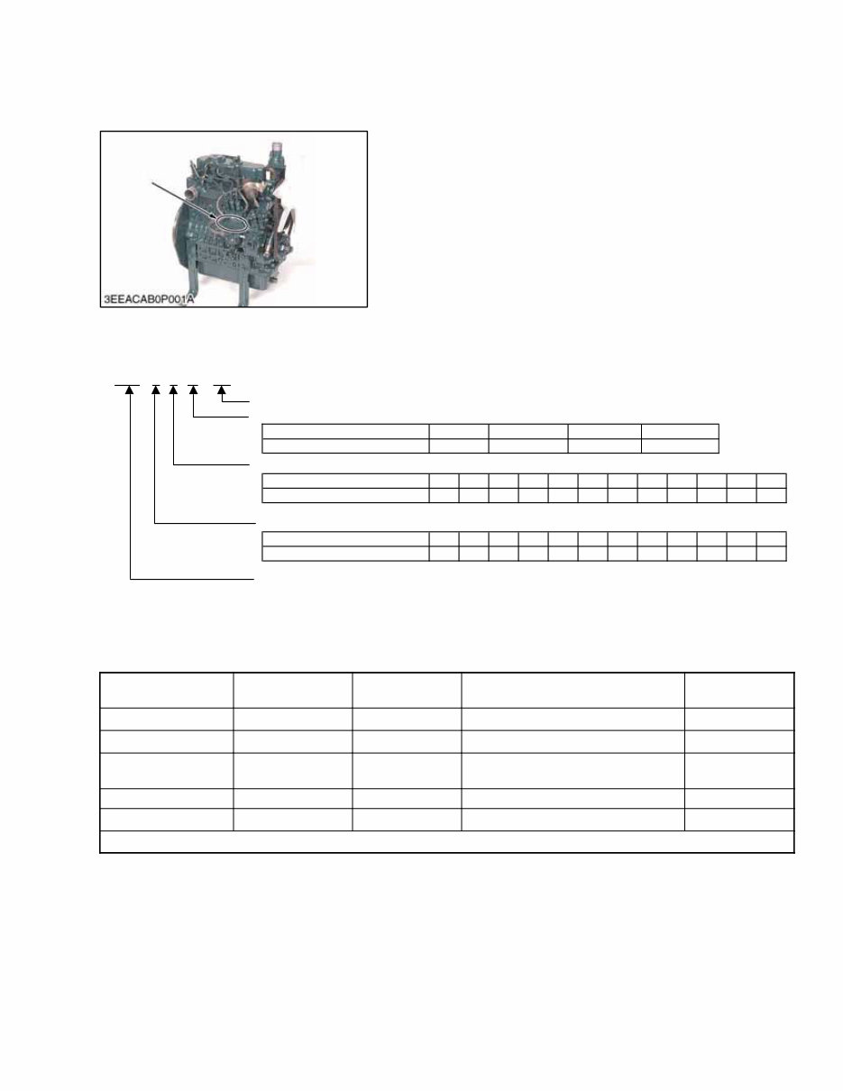
1--1 62--11161 SECTION 1 General 1.1 ENGINE IDENTIFICATION S/N When contacting Carrier Transicold, always specify your engine model number and serial number. The engine model and its serial number need to be identified before the engine can be serviced or parts replaced. Engine Serial Number (S/N) The engine serial number is an identified number for the engine. It is marked after the engine model number. It indicates basic model, month, year and sequence of manufacture as follows: Serial Number 7 K A Last 3 Digits in Numerals (1 to 999 Units in Sequence) 6th Digit Alpabetical Letter (Month of Manufacture -- 1st Letter 1--9999 Units, 2nd Letter 10,000--19,998 Units) Alphabetical letter A,B C,D E,F G,H J,K L,M N,P Q,R S,T U,V W,X Y,Z Month 5th Digit Alpabetical Letter or Numerals (Year of Manufacture) Alphabetical letter or numerals W X Y Year 98 99 00 01 02 03 04 05 06 07 08 09 Jan Feb Mar May Jun Jul Aug Sep Oct Apr Nov Dec 1 2 3 4 5 6 7 8 9 Z482-- Basic model number 176 7th Digit Sequential Numeral or Letter (Units Manufactured) Alphabetical Numeral or Letter Unit Number Sequence A to 19,998 19,999--20997 20,998--21,996 B C 21,997--22,995 0 to 9 Table 1-1. Model Chart KUBOTA MODEL NO. CARRIER MODEL NO. NEW ENGINE PART NO. PRIMARY USE REPLACES Z482--E2B CT2--29--TV 26--60001--03* SOLARA Units 26--60001--01 Z482--E2B CT2--29--TV 26--60001--04* SUPRA Units 26--60001--02 Z482--E2B--ATC--1 CT2--29--TV 96-- 101--05K ProHeat / ComfortPro PC5000 Units NEW Z482--E2B--TFX--1 CT2--29--TV 96-- 101--20K ComfortPro PC6000 Units NEW D722--E2B CT3--44--TV 26--60000--05* GENESIS Units 26--60000--00 * Beginning with Serial Number 5A0001
1--2 62--11161 1.2 ENGINE SPECIFICATIONS Table 1-2. Specification Chart MODEL NUMBER (Carrier / Kubota) CT2--29--TV / Z482--E2B CT3--44--TV / D722--E2B TYPE Vertical, Water--cooled, 4 cycle IDI diesel engine NUMBER OF CYLINDERS 2 3 BORE X STROKE mm X mm (in. X in.) 67 X 68 (2.64 X 2.68) TOTAL DISPLACEMENT cm 3 (cu.in.) 479 (29.23) 719 (43.88) BRAKE HORSEPOWER SAE Intermittent H.P. kW (HP) / RPM 9.3 (12.5) / 3600 14.0 (18.0) / 3600 MAXIMUM BARE SPEED RPM 3800 IDLING SPEED RPM 900 To 1000 COMBUSTION CHAMBER Spherical Type (E--TVCS) FUEL INJECTION PUMP Bosch MD Type Mini Pump GOVERNOR Centrifugal Ball Mechanical Governor INJECTION NOZZLE Bosch Throttle--Type INJECTION TIMING (before T.D.C.) 19 to 21° FIRING ORDER 1--2 1--2--3 INJECTION PRESSURE (Valve Opening Pressure) 13.73 MPa (140 kgf/cm 2 , 1991 psi.) COMPRESSION RATIO 23.5 : 1 LUBRICATING SYSTEM Forced Lubrication by Pump COOLING SYSTEM Pressurized Radiator, Forced Circulation With Water Pump STARTING SYSTEM Cell Starter (With Glow Plug) STARTING MOTOR 12V, 0.8 kW RECOMMENDED BATTERY CAPACITY (5 Hour Capacity) 12V, 28AH, equivalent 12V, 36AH, equivalent CHARGING GENERATOR 12V, 150 W 12V, 150 W FUEL Diesel Fuel No.2--D (ASTM D975) LUBRICATING OIL *Quality Better Than CF Class (API), SAE 10W--30 or 15W--40 LUBRICATING OIL CAPACITY 2.5 L (2.64 U.S. Quarts) 3.8 L (4.02 U.S. Quarts) 3.3 L (3.5 U.S. Quarts) (TFX--1 Only) Weight (DRY) kg (lbs.) 53.1 (117.1) 63.1 (139.1) *See paragraph 1.7.2.
1--3 62--11161 1.2.1 E2B ENGINE Carrier/Kubota supply diesel engines conforming to federal emission regulations. The emission controls that have been put into effect have been stepped up to the second stage. Carrier/Kubota has executed the improvement in the engines to conform to this regulation. In order to discriminate between engines conforming to Tier 1 / Phase 1 requirements and those conforming to Tier 2 / Phase 2 requirements, we have adapted E2B as a new model name for the engines conforming to Tier2 / Phase 2 regulations. In the after--sale services for Tier 2 / Phase 2 engines, only use the dedicated parts for E2B models and carry out the maintenance services accordingly. 1.2.2 CYLINDER NUMBER The cylinder numbers of diesel engines are designated as shown above. The sequence of cylinder numbers is given as No.1, No. 2, and No. 3 starting from the gear case end of the engine. 1.3 GENERAL PRECAUTIONS During disassembly, carefully arrange removed parts in a clean area to prevent confusion latter. Screws, bolts and nuts should be replaced in their original position to prevent reassembly errors. When special tools are required, use Carrier Transicold genuine special tools. Special tools which are not frequently used should be made according to the drawings provided. Before disassembling or servicing electrical wires, make sure to always disconnect the grounding cable from the battery first. Remove oil and dirt from parts before taking any measurements. Use only Carrier Transicold genuine parts for parts replacements to maintain engine performance and to ensure safety. Gaskets and o--rings must be replaced during reassembly. Apply grease to new o--rings or oil seals before assembling. 1 2 3 2 3 1. Grease 2. Force 3. Place the Sharp Edge against the Direction of Force A External Snap Ring B Internal Snap Ring When reassembling external or internal snap rings, position them so that the sharp edge faces against the direction from which force is applied. A newly serviced or reassembled engine should be run--in with no load for 15 minutes. Serious damage to the engine may result otherwise.
The Kubota Z482-B-E Engine Repair Service Manual is a comprehensive guide designed for professional technicians and do-it-yourself mechanics alike. It is tailored to individuals with basic knowledge in electrical and mechanical concepts, providing essential information for maintaining and repairing the Kubota Z482-B-E Engine.
Delivered in a printable PDF format, this manual covers a wide range of topics including engine removal, wiring diagrams, lubrication points, periodic maintenance, fuel and lubrication systems, electrical systems, chassis, suspension, gearbox, cooling system, and detailed specifications. It also includes step-by-step repair procedures, critical specifications, illustrations, disassembly and assembly instructions, cleaning and reinstalling procedures, and more.
Whether you are a professional mechanic or a DIY enthusiast, this manual will guide you through fundamental repair and maintenance tasks, empowering you to make informed decisions about your Kubota Z482-B-E Engine. It is compatible with all versions of Windows and Mac, and can be instantly accessed after download.
With the Kubota Z482-B-E Engine Repair Service Manual, you can gain the knowledge and confidence to effectively maintain and repair your engine, ensuring its optimal performance and longevity.
File Format: PDF
Language: English
Specifications: Full Printable
Zoom IN/OUT: Yes
Delivery: Instant
Requirements: Adobe Reader & Win
Compatible: All Versions of Windows & Mac
Get your hands on the Kubota Z482-B-E Engine Repair Service Manual and take control of your engine's maintenance and repair needs.