LIST OF ABBREVIATIONS A ampere(s) lb pound(s) ABDC after bottom dead center m meter(s) AC alternating current min minute(s) ATDC after top dead center N newton(s) BBDC before bottom dead center Pa pascal(s) BDC bottom dead center PS horsepower BTDC before top dead center psi pound(s) per square inch C degree(s) Celsius r revolution DC direct current rpm revolution(s) per minute F farad(s) TDC top dead center F degree(s) Fahrenheit TIR total indicator reading ft foot, feet V volt(s) g gram(s) W watt(s) h hour(s) ohm(s) L liter(s) Read OWNER’S MANUAL before operating. Downloaded from www.Manualslib.com manuals search engine
EMISSION CONTROL INFORMATION To protect the environment in which we all live, Kawasaki has incorporated crankcase emission (1) and exhaust emission (2) control systems (EM) in compliance with applicable regulations of the United States Environmental Protection Agency and California Air Resources Board. 1. Crankcase Emission Control System A sealed-type crankcase emission control system is used to eliminate blow-by gases. The blow-by gases are led to the breather chamber through the crankcase. Then, it is led to the air cleaner. Oil is separated from the gases while passing through the inside of the breather chamber from the crankcase, and then returned back to the bottom of crankcase. 2. Exhaust Emission Control System The exhaust emission control system applied to this engine consists of a carburetor and an ignition system having optimum ignition timing characteristics. The carburetor has been calibrated to provide lean air/fuel mixture characteristics and optimum fuel economy with a suitable air cleaner and exhaust system. TAMPERING WITH EMISSION CONTROL SYSTEM PROHIBITED Federal law and California State law prohibits the following acts or the causing thereof: (1) the removal or rendering inoperative by any person other than for purposes of maintenance, repair, or replacement, of any device or element of design incorporated into any new engine for the purpose of emission control prior to its sale or delivery to the ultimate purchaser or while it is in use, or (2) the use of the engine after such device or element of design has been removed or rendered inoperative by any person. Among those acts presumed to constitute tampering are the acts listed below: Do not tamper with the original emission related part: • Carburetor and internal parts • Spark plugs • Magneto or electronic ignition system • Fuel filter element • Air cleaner elements • Crankcase • Cylinder heads • Breather chamber and internal parts • Intake pipe and tube Downloaded from www.Manualslib.com manuals search engine
Foreword This manual is designed primarily for use by trained mechanics in a properly equipped shop. However, it contains enough detail and basic information to make it useful to the owner who desires to perform his own basic maintenance and repair work. A basic knowledge of mechanics, the proper use of tools, and workshop procedures must be understood in order to carry out maintenance and repair satisfactorily. Whenever the owner has insufficient experience or doubts as to his ability to do the work, all adjustments, maintenance, and repair should be carried out only by qualified mechanics. In order to perform the work efficiently and to avoid costly mistakes, read the text, thoroughly familiarize yourself with the procedures before starting work, and then do the work carefully in a clean area. Whenever special tools or equipment are specified, do not use makeshift tools or equipment. Precision measurements can only be made if the proper instruments are used, and the use of substitute tools may adversely affect safe operation. To get the longest life out of your engine: • Follow the Periodic Maintenance Chart in the Service Manual. • Be alert for problems and non-scheduled maintenance. • Use proper tools and genuine Kawasaki engine parts. Genuine parts provided as spare parts are listed in the Parts Catalog. • Follow the procedures in this manual carefully. Don’t take shortcuts. • Remember to keep complete records of maintenance and repair with dates and any new parts installed. How to Use This Manual In this manual, the product is divided into its major sys- tems and these systems make up the manual’s chapters. The Quick Reference Guide shows you all of the product’s system and assists in locating their chapters. Each chap- ter in turn has its own comprehensive Table of Contents. For example, if you want ignition coil information, use the Quick Reference Guide to locate the Electrical System chapter. Then, use the Table of Contents on the first page of the chapter to find the Ignition coil section. Whenever you see these WARNING and CAUTION symbols, heed their instructions! Always follow safe operating and maintenance practices. This warning symbol identifies special instruc- tions or procedures which, if not correctly fol- lowed, could result in personal injury, or loss of life. CAUTION This caution symbol identifies special instruc- tions or procedures which, if not strictly ob- served, could result in damage to or destruction of equipment. This manual contains four more symbols (in addition to WARNING and CAUTION) which will help you distinguish different types of information. NOTE This note symbol indicates points of particular in- terest for more efficient and convenient operation. • Indicates a procedural step or work to be done. Indicates a procedural sub-step or how to do the work of the procedural step it follows. It also precedes the text of a WARNING, CAUTION, or NOTE. Indicates a conditional step or what action to take based on the results of the test or inspection in the procedural step or sub-step it follows. In most chapters an exploded view illustration of the system components follows the Table of Contents. In these illustrations you will find the instructions indicating which parts require specified tightening torque, oil, grease or a locking agent during assembly. Downloaded from www.Manualslib.com manuals search engine
GENERAL INFORMATION 1-1 General Information Table of Contents 1 Before Servicing................................................................................................................................................................ 1-2 Model Identification ........................................................................................................................................................... 1-4 General Specifications ...................................................................................................................................................... 1-5 Torque and Locking Agent ................................................................................................................................................ 1-6 Special Tools ..................................................................................................................................................................... 1-8 Downloaded from www.Manualslib.com manuals search engine
1-2 GENERAL INFORMATION Before Servicing Before starting to service the engine, carefully read the applicable section to eliminate unnecessary work. Photographs, diagrams, notes, cautions, warnings, and detailed descriptions have been included wherever necessary. Nevertheless, even a detailed account has limitations, a certain amount of basic knowledge is required for successful work. Especially note the following: (1) Dirt Before removal and disassembly, clean the engine. Any dirt entering the engine, carburetor, or other parts, will work as an abrasive and shorten the life of engine. For the same reason, before installing a new part, clean off any dust or metal filings. (2) Battery Ground Remove the ground (—) lead from the battery before performing any disassembly operations on the equipment. This prevents: (a) the possibility of accidentally turning the engine over while partially disassembled. (b) sparks at electrical connections which will occur when they are disconnected. (c) damage to electrical parts. (3) Tightening Sequence Generally, when installing a part with several bolts, nuts, or screws, start them all in their holes and tighten them to a snug fit. Then tighten them evenly, in a staggered sequence. This is to avoid distortion of the part and/or causing gas or oil leakage. Conversely when loosening the bolts, nuts, or screws, first loosen all of them by about a quarter of a turn and then remove them. Where there is a tightening sequence indication in this Service Manual, the bolts, nuts, or screws must be tightened in the order and method indicated. (4) Torque When torque values are given in this Service Manual, use them. Either too little or too much torque may lead to serious damage. Use a good quality, reliable torque wrench. (5) Force Common sense should dictate how much force is necessary in assembly and disassembly. If a part seems especially difficult to remove or install, stop and examine what may be causing the problem. Whenever tapping is necessary, tap lightly using a wooden or plastic-faced mallet. Use an impact driver for screws (particularly for the removal of screws held by a locking agent) in order to avoid damaging the heads. (6) Edges Watch for sharp edges, especially during major engine disassembly and assembly. Protect your hands with gloves or a piece of thick cloth when lifting the engine or turning it over. (7) High-Flash Point Solvent A high-flash point solvent is recommended to reduce fire danger. A commercial solvent commonly available in North America is Standard solvent (generic name). Always follow manufacturer and container directions regarding the use of any solvent. (8) Gasket, O-Ring Do not reuse a gasket or O-ring once it has been in service. The mating surfaces around the gasket should be free of foreign matter and perfectly smooth to avoid oil or compression leaks. (9) Liquid Gasket, Non-Permanent Locking Agent Follow manufacturer’s directions for cleaning and preparing surfaces where these compounds will be used. Apply sparingly. Excessive amounts may block engine oil passages and cause serious damage. An example of a non- permanent locking agent commonly available in North America is Loctite Lock’n Seal (Blue). (10) Press A part installed using a press or driver, such as a journal, should first be coated with oil on its outer or inner circumference so that it will go into place smoothly. (11) Ball Bearing When installing a ball bearing, the bearing race which is affected by friction should be pushed by a suitable driver. This prevents severe stress on the balls and races, and prevents races and balls from being dented. Press a ball bearing until it stops at the stop in the hole or on the shaft. (12) Oil Seal and Grease Seal Replace any oil or grease seals that were removed with new ones, as removal generally damages seals. When pressing in a seal which has manufacturer’s marks, press it in with the marks facing out. Seals should be pressed into place using a suitable driver, which contacts evenly with the side of seal, until the face of the seal is even with the end of the hole. (13) Seal Guide A seal guide is required for certain oil or grease seals during installation to avoid damage to the seal lips. Before a shaft passes through a seal, apply a little oil, preferably high temperature grease on the lips to reduce rubber to metal friction. (14) Circlip, Retaining Ring Replace any circlips and retaining rings that were removed with new ones, as removal weakens and deforms them. When installing circlips and retaining rings, take care to compress or expand them only enough to install them and no more. Downloaded from www.Manualslib.com manuals search engine
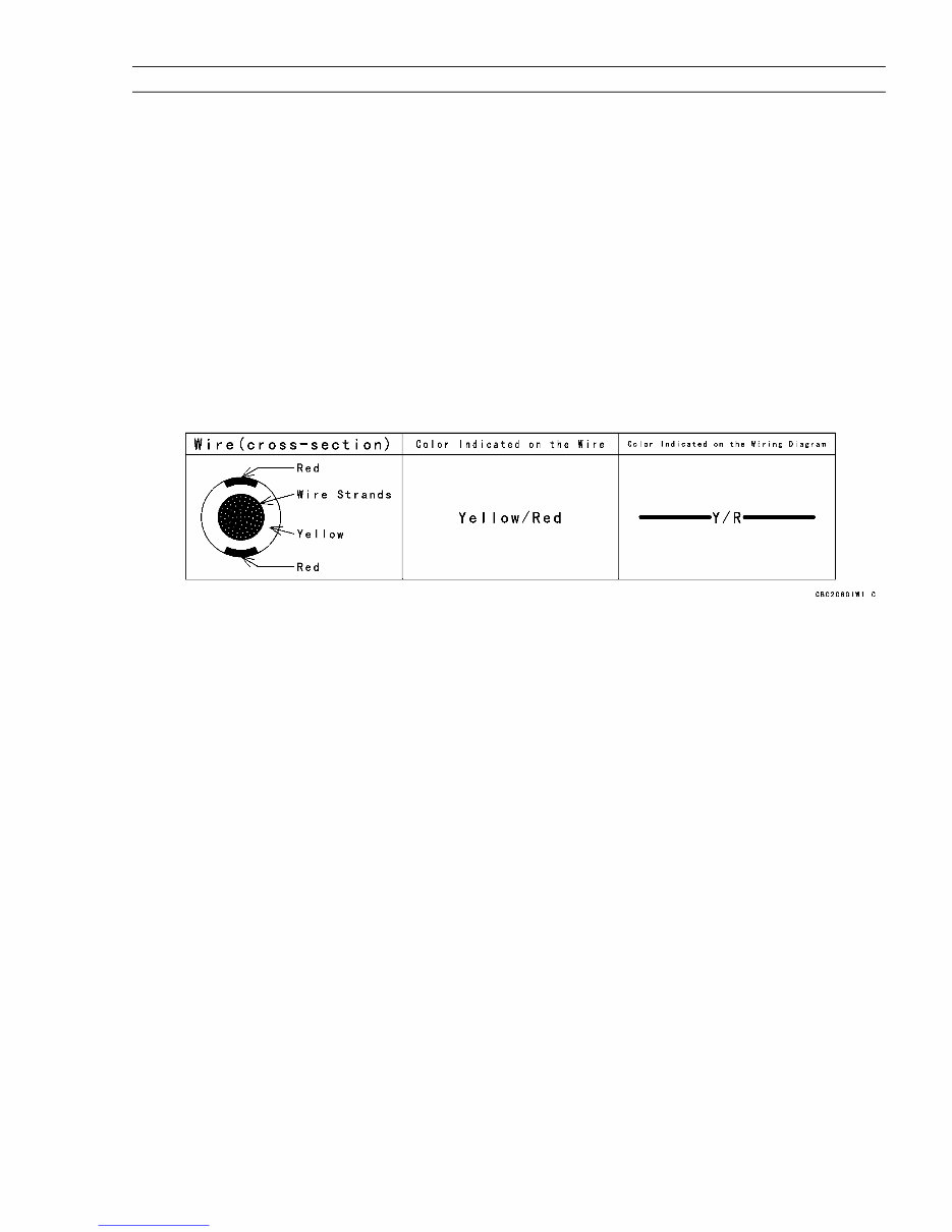
GENERAL INFORMATION 1-3 Before Servicing (15) Cotter Pin Replace any cotter pins that were removed with new ones, as removal deforms and breaks them. (16) Lubrication Engine wear is generally at its maximum while the engine is warming up and before all the rubbing surfaces have an adequate lubricative film. During assembly, oil or grease (whichever is more suitable) should be applied to any rubbing surface which has lost its lubricative film. Old grease and dirty oil should be cleaned off. Deteriorated grease has lost its lubricative quality and may contain abrasive foreign particles. Don’t use just any oil or grease. Some oils and greases in particular should be used only in certain applications and may be harmful if used in an application for which they are not intended. This manual makes reference to molybdenum disulfide grease (MoS2) in the assembly of certain engine parts. Always check manufacturer recommendations before using such special lubricants. (17) Electrical Wires All the electrical wires are either single-color or two-color and, with only a few exceptions, must be connected to wires of the same color. On any of the two-color wires there is a greater amount of one color and a lesser amount of a second color, so a two-color wire is identified by first the primary color and then the secondary color. For example, a yellow wire with thin red stripes is referred to as a "yellow/red" wire; it would be a "red/yellow" wire if the colors were reversed to make red the main color. (18) Replacement Parts When there is a replacement instruction, replace these parts with new ones every time they are removed. There replacement parts will be damaged or lose their original function once removed. (19) Inspection When parts have been disassembled, visually inspect these parts for the following conditions or other damage. If there is any doubt as to the condition of them, replace them with new ones. Abrasion Crack Hardening Warp Bent Dent Scratch Wear Color change Deterioration Seizure (20) Specifications Specification terms are defined as follows: "Standards" show dimensions or performances which brand-new parts or systems have. "Service Limits" indicate the usable limits. If the measurement shows excessive wear or deteriorated performance, replace the damaged parts. Downloaded from www.Manualslib.com manuals search engine
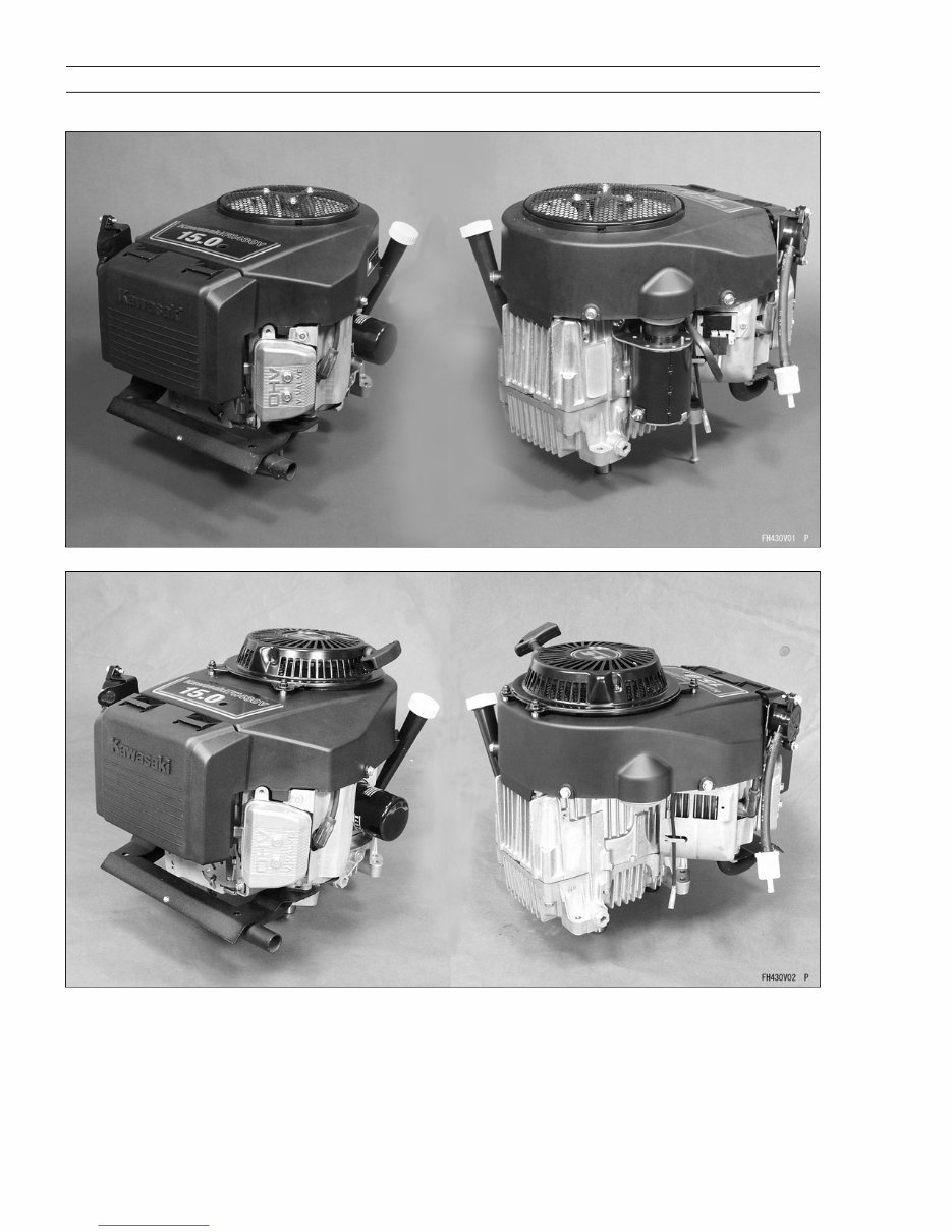
1-4 GENERAL INFORMATION Model Identification Electric Starter Model Recoil Starter Model Cylinder Number Designation: No.1 Cylinder is the left-hand cylinder viewed from the air cleaner. No.2 Cylinder is the right-hand cylinder viewed from the air cleaner. Downloaded from www.Manualslib.com manuals search engine
GENERAL INFORMATION 1-5 General Specifications Items FH381V, FH430V Type of engine Forced air-cooled, vertical shaft, OHV, 4-stroke gasoline engine. Cylinder layout 90 V-Twin Bore x Stroke 65 mm x 65 mm (2.56 in x 2.56 in) Piston displacement 431 mL (26.3 cu. in) Direction of rotation Counterclockwise facing the PTO shaft Compression release Automatic compression release Low idle speed 1550 rpm Fast idle speed 3600 rpm Ignition system Transistorized-fly wheel magneto RFI Per Canada and U.S.A. requirements Starting system Electric starter and/or recoil starter Charging system 12 V - 15 amps with regulator Spark plug CHAMPION RCJ8Y Carburetor Float type, fixed main jet Fuel pump Diaphragm type pulse pump Air cleaner Dual stage element, dry type Governor Flyweight all speed governor Lubrication system Pressure feed by positive displacement pump Oil filter Cartridge type full flow filter Oil capacity (when engine is completely dry) 1.8 L (1.9 US-qt) Cooling system Forced air cooling by fan Dimensions (L x W x H ) 421 mm x 350 mm x 325 mm Electric starter model (16.6 in x 13.8 in x 12.8 in) 421 mm x 350 mm x 353 mm Recoil starter model (16.6 in x 13.8 in x 13.9 in) Dry weight Electric starter model 31.8 kg (70.1 lb) Recoil starter model 29.8 kg (65.7 lb) Specifications subject to change without notice. Downloaded from www.Manualslib.com manuals search engine
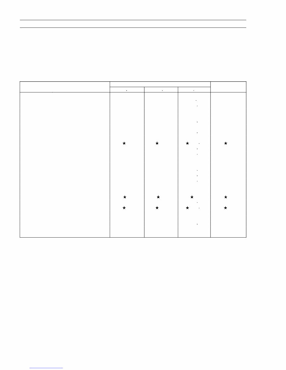
1-6 GENERAL INFORMATION Torque and Locking Agent The following tables list the tightening torque for the major fasteners, and the parts requiring use of a non-permanent locking agent or liquid gasket. Letters used in the "Remarks" column mean: L: Apply a non-permanent locking agent to the threads. M: Apply a molybdenum disulfide lubricant (grease or oil) to the threads, seated surface, or washer. O: Apply an oil to the threads, seated surface, or washer. S: Tighten the fasteners following the specified sequence. SS : Apply silicone sealant. Fastener Torque Remarks Nm kgf m ft lb Fuel System: Throttle Valve Screws 0.7 0.07 6 in lb Main Jet 2.3 0.23 20 in lb Float Chamber Mounting Bolt 4.5 0.46 40 in-lb (Carburetor) Governor Arm Clamp Nut 7.8 0.80 69 in lb Governor Shaft Plate Screws 2.0 0.20 18 in-lb Holder Plate Nuts (Air Cleaner, 5.9 0.60 52 in lb Carburetor Mounting) Intake Manifold Mounting Bolts 6.9 0.70 61 in lb =S Cleaner Body Mounting Bolts 5.9 0.60 52 in lb Control Panel Mounting Bolts 5.9 0.60 52 in lb Cooling System: Engine-shroud Bolt (M8) 15 1.5 11 Engine-shroud Bolts (M6) 5.9 0.60 52 in lb Engine-shroud Bolts (Studs) 7.8 0.80 69 in lb Plug Screw (Engine-shroud) 3.4 0.35 30 in lb Flywheel Bolt 56 5.7 41 Engine Top End Cylinder Head Bolts 25 2.6 19 =S Valve Clearance Lock Screws 6.9 0.70 61 in lb Connecting Rod Big End 5.9 0.60 52 in lb =O Cap Bolts Rocker Arm Bolts 28 2.8 20 Rocker Cover Mounting Bolts 5.9 0.60 52 in lb Exhaust Pipe Flange Nuts 15 1.5 11 Spark Plugs 22 2.2 16 Downloaded from www.Manualslib.com manuals search engine
This is a comprehensive factory service repair manual for the Kawasaki FH381V FH430V 4-Stroke Air Cooled V-Twin Gasoline Engine. It contains detailed illustrations and step-by-step instructions, making it suitable for both do-it-yourself enthusiasts and experienced mechanics. The manual provides instructions based on the complete disassembly of the machine, accompanied by numerous photos and illustrations to guide the reader through each service and repair procedure.
It comes in PDF format, compatible with all PC-based Windows operating systems and Mac. All pages are printable, offering an inexpensive way to ensure the proper functioning of your vehicle.
This manual is known by various names, including Kawasaki FH381V FH430V 4-Stroke Air Cooled V-Twin Gasoline Engine Service Manual, Repair Manual, Workshop Manual, and Service Repair Manual.
The Service Repair Manual covers:
General Information
Periodic Maintenance
Fuel System
Cooling System
Engine Top End
Lubrication System
Camshaft / Crankshaft
Starter System
Electrical System
Troubleshooting
This manual is an instant digital download, saving on postage and packaging costs. It is essential for anyone looking to save money and gain a deeper understanding of their International vehicle.
File Format: PDF
Compatible: All Versions of Windows & Mac
Language: English
Requirements: Adobe Reader
It is important to invest in the right repair manual for your Kawasaki FH381V FH430V 4-Stroke Air Cooled V-Twin Gasoline Engine. Having this manual will save you money and provide valuable insights into your vehicle in the long run. All pages are printable.
Recently Viewed
5,521,897Happy Clients
2,594,462eManuals
1,120,453Trusted Sellers
15Years in Business
Price:
Actual Price:
Kawasaki FH381V FH430V 4-Stroke Air Cooled V-Twin Gasoline Engine Workshop Service Repair Manual