NEF ENGINES F4BE - F4GE Mechanical Injection F4CE Mechanical Injection F4AE - F4HE Common Rail F4DE Common Rail - Industrial applications Technical and Repair manual
Publication edited by Iveco Motors Iveco SpA PowerTrain Mkt. Advertising & Promotion Viale dell’Industria, 15/17 20010 Pregnana Milanese Milano (Italy) Print P2D32N001E -1 st Ed. 08.2004 This publication describes the characteristics, data and correct methods for repair operations on each component of the ve- hicle. If the instructions provided are followed and the specified equipment is used, correct repair operations in the pro- grammed time will be ensured, safeguarding against possible accidents. Before starting to perform whatever type of repair, ensure that all accident prevention equipment is available and efficient. All protections specified by safety regulations, i.e.: goggles, helmet, gloves, boot, etc. must be checked and worn. All machining, lifting and conveying equipment should be in- spected before use. The data contained in this publication was correct at the time of going to press but due to possible modifications made by the Manufacturer for reasons of a technical or commercial na- ture or for adaptation to the legal requirements of the differ- ent countries, some changes may have occurred. No part of this publication, including the pictures, may be re- produced in any form or by any means. B.U. TECHNICAL PUBLISHING Iveco Technical Publications Lungo Stura Lazio, 15/19 10156 Turin - Italy Produced by:
F4BE - F4GE NEF engines Part 1 F4CE NEF engines Part 2 F4AE - F4HE NEF engines Part 3 F4DE NEF engines Part 4 NEF ENGINES 1 NEF ENGINES
2 NEF ENGINES
Where possible, the same sequence of procedures has been followed for easy reference. Diagrams and symbols have been widely used to give a clearer and more immediate illustration of the subject being dealt with, (see next page) instead of giving descriptions of some operations or procedures. Example Ø 1 = housing for connecting rod small end bush Ø 2 = housing for connecting rod bearings α Tighten to torque Tighten to torque + angular value 1 ∅ ∅ 2 3 NEF ENGINES SPECIAL REMARKS
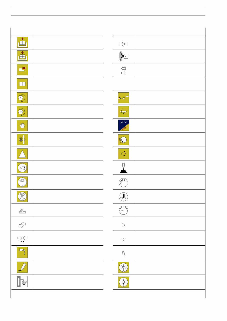
4 NEF ENGINES Graph and symbols Removal Disconnection Intake Refitting Connection Exhaust Removal Disassembly Operation Fitting in place Assembly ρ Compression ratio Tighten to torque Tolerance Weight difference α Tighten to torque + angle value Rolling torque Press or caulk Replacement Original spare parts Regulation Adjustment Rotation ! Warning Note Angle Angular value Visual inspection Fitting position check Preload Measurement Value to find Check Number of revolutions Equipment Temperature Surface for machining Machine finish bar Pressure Interference Strained assembly Oversized Higher than…. Maximum, peak Thickness Clearance Undersized Less than…. Minimum Lubrication Damp Grease Selection Classes Oversizing Sealant Adhesive Temperature < 0 °C Cold Winter Air bleeding Temperature > 0 °C Hot Summer
Section General specifications 1 Fuel 2 Duty - Industrial applications Mechanical injection Engines 3 Overhaul and technical specifications 4 Tools 5 Safety prescriptions Appendix PREFACE TO USER’S GUIDELINE MANUAL Section 1 describes the NEF engine illustrating its features and working in general. Section 2 describes the type of fuel feed. Section 3 relates to the specific duty and is divided in four se- parate parts: 1. Mechanical part, related to the engine overhaul, limited to those components with different characteristics based on the relating specific duty. 2. Electrical part, concerning wiring harness, electrical and electronic equipment with different characteristics based on the relating specific duty. 3. Maintenance planning and specific overhaul. 4. Troubleshooting part dedicated to the operators who, being entitled to provide technical assistance, shall have sim- ple and direct instructions to identify the cause of the major inconveniences. Sections 4 and 5 illustrate the overhaul operations of the en- gine overhaul on stand and the necessary equipment to exe- cute such operations. Installation general prescriptions are reported within the ap- pendix. The appendix reports general safety prescriptions to be follo- wed by all operators whether being in-charge of installation or maintenance, in order to avoid serious injury. Part 1 F4BE - F4GE NEF ENGINES 1 F4BE - F4GE NEF ENGINES
2 F4BE - F4GE NEF ENGINES
3 F4BE - F4GE NEF ENGINES UPDATING Section Description Page Date of revision
Get access to the Iveco NEF F4BE F4GE F4CE F4AE F4HE F4DE Engine Workshop Service & Repair Manual, a comprehensive resource for working on your vehicle. This manual provides step-by-step instructions and detailed exploded pictures to guide you through the required job efficiently. It covers a range of engines including NEF ENGINES:
F4BE - F4GE Mechanical Injection
F4CE - Mechanical Injection
F4AE - F4HE Common Rail
F4DE - Common Rail - Industrial Applications
It includes service manual sections such as General Information, Engine, Fuel, Duty Industrial Applications, Mechanical Injection, Overhaul, Tools, Safety, Maintenance, and Technical Information & Specifications. This manual is designed in PDF format for easy viewing on various devices and can be printed for convenience. It's the only workshop service manual you'll ever need, and it's available for instant download without any shipping costs. For specific manuals, you can search our shop or contact our customer support team. Thank you for visiting our page!