

DENSO New Common Rail System for ISUZU 4HK1 / 6HK1 Engine
What's Included?
Fast Download Speeds
Online & Offline Access
Access PDF Contents & Bookmarks
Full Search Facility
Print one or all pages of your manual
00400056E
Common Rail System for ISUZU
SERVICE MANUAL
OPERATION
4HK1 / 6HK1 Type Engine
February, 2004
Diesel Injection Pump

FORWARD
To meet the high pressurization requirements for the engine to deliver cleaner exhaust gas emissions, lower fuel
consumption and reduced noise, advanced electronic control technology is being adopted in the fuel injection system.
This manual covers the electronic control model Common Rail system with HP3/HP4 pump for the ISUZU 4HK1/6HK1
type engines which are used to ELF and GM 560 series respectively. Complex theories, special functions and
components made by manufacturers other than DENSO are omitted from this manual.
This manual will help the reader develop an understanding of the basic construction, operation and system configuration
of the DENSO manufactured components and brief diagnostic information.
TABLE OF CONTENTS
1. Product Application . . . . . . . . . . . . . . . . . . . . . . . . . . . . . . . . . . . . . . . . . . . . . . . . . . . . . . . . . . . . . . . . . . . . . . . . . . . . . . . . . . . . 1
1-1. Application . . . . . . . . . . . . . . . . . . . . . . . . . . . . . . . . . . . . . . . . . . . . . . . . . . . . . . . . . . . . . . . . . . . . . . . . . . . . . . . . . . . . . . . 1
1-2. System Components Parts Numbers . . . . . . . . . . . . . . . . . . . . . . . . . . . . . . . . . . . . . . . . . . . . . . . . . . . . . . . . . . . . . . . . . . 1
2. Outline . . . . . . . . . . . . . . . . . . . . . . . . . . . . . . . . . . . . . . . . . . . . . . . . . . . . . . . . . . . . . . . . . . . . . . . . . . . . . . . . . . . . . . . . . . . . . . . 2
2-1. Outline of System . . . . . . . . . . . . . . . . . . . . . . . . . . . . . . . . . . . . . . . . . . . . . . . . . . . . . . . . . . . . . . . . . . . . . . . . . . . . . . . . . . 2
2-2. Outline of System . . . . . . . . . . . . . . . . . . . . . . . . . . . . . . . . . . . . . . . . . . . . . . . . . . . . . . . . . . . . . . . . . . . . . . . . . . . . . . . . . . 4
2-3. Fuel System and Control System . . . . . . . . . . . . . . . . . . . . . . . . . . . . . . . . . . . . . . . . . . . . . . . . . . . . . . . . . . . . . . . . . . . . . 5
3. Construction and Operation . . . . . . . . . . . . . . . . . . . . . . . . . . . . . . . . . . . . . . . . . . . . . . . . . . . . . . . . . . . . . . . . . . . . . . . . . . . . . 6
3-1. Description of Main Components . . . . . . . . . . . . . . . . . . . . . . . . . . . . . . . . . . . . . . . . . . . . . . . . . . . . . . . . . . . . . . . . . . . . . 6
3-2. Description of Control System Components . . . . . . . . . . . . . . . . . . . . . . . . . . . . . . . . . . . . . . . . . . . . . . . . . . . . . . . . . . 22
3-3. Various Types of Control . . . . . . . . . . . . . . . . . . . . . . . . . . . . . . . . . . . . . . . . . . . . . . . . . . . . . . . . . . . . . . . . . . . . . . . . . . . 24
3-4. Engine ECU . . . . . . . . . . . . . . . . . . . . . . . . . . . . . . . . . . . . . . . . . . . . . . . . . . . . . . . . . . . . . . . . . . . . . . . . . . . . . . . . . . . . . . 31
-1-
1. Product Application
1-1. Application
1-2. System Components Parts Numbers
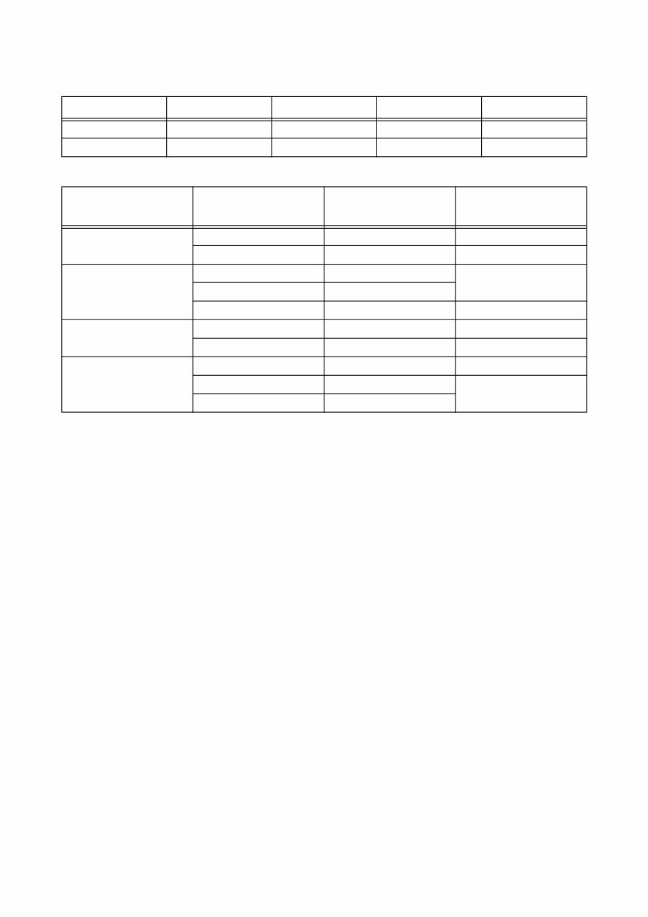
Vehicle Name Engine Model Vehicle model Exhaust Volume Reference
ELF 4HK1 N series 5.2L Direct-Injection
C560 Series 6HK1 GM 560 7.8L Direct-Injection
Parts Name DENSO Parts Number
Car Manufacturer Parts
Number
Reference
Supply Pump 294000-0260 8973288860 4HK1
294050-0021 9876020491 6HK1
Injector 095000-5351 8976011561 6HK1
095000-5361 8976028031
095000-5471 8973297031 4HK1
Rail 095440-0351 8973060632 4HK1
095440-0470 8973230190 6HK1
Engine ECU 275800-2801 8151794773 6HK1
275800-2812 8973750190 4HK1
275800-2822 8973750200
-2-
2. Outline
2-1. Outline of System
The common rail system was developed primarily to cope with exhaust gas regulations for diesel engines, and aimed for
1. further improved fuel economy; 2. noise reduction; and 3. high power output.
A. System Characteristics
The common rail system uses a type of accumulation chamber called a rail to store pressurized fuel, and injectors that
contain electronically controlled solenoid valves to spray the pressurized fuel into the cylinders.
Because the engine ECU controls the injection system (including the injection pressure, injection rate, and injection tim-
ing), the injection system is unaffected by the engine speed or load.
This ensures a stable injection pressure at all times, particularly in the low engine speed range, and dramatically decreas-
es the amount of black smoke ordinarily emitted by a diesel engine during start-up and acceleration.
As a result, exhaust gas emissions are cleaner and reduced, and higher power output is achieved.
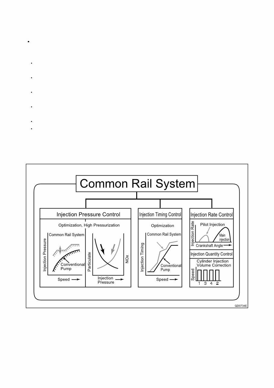
a. Injection Pressure Control
Enables high-pressure injection even at low engine speeds.
Optimizes control to minimize particulate matter and NOx emissions.
b. Injection Timing Control
Enables finely tuned optimized control in accordance with driving conditions.
c. Injection Rate Control
Pilot injection control sprays a small amount of fuel before the main injection.
d. EGR (Exhaust Gas Recirculation) Control
By recirculating the exhaust gas into the intake side of the engine, the combustion temperature is reduced and NOx is
decreased.
-3-
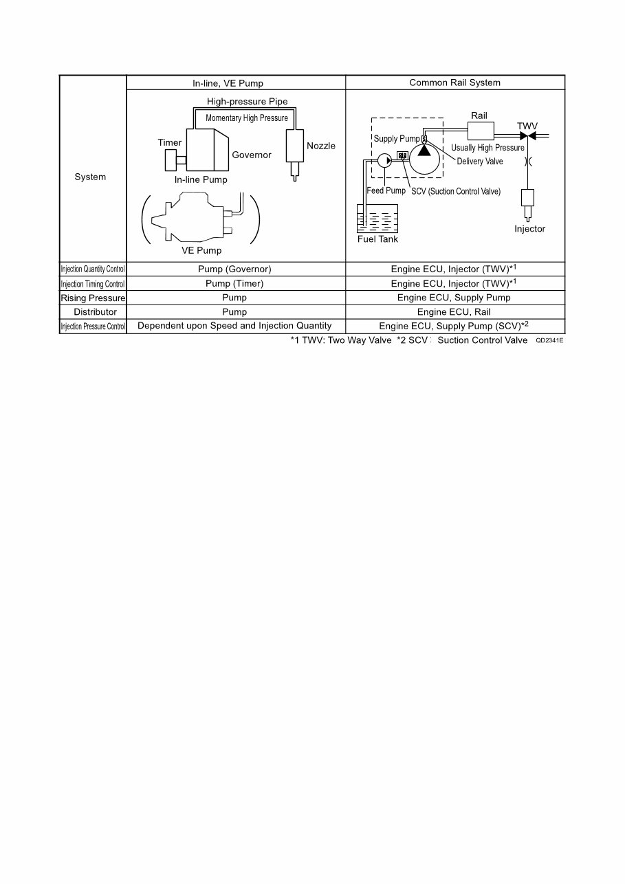
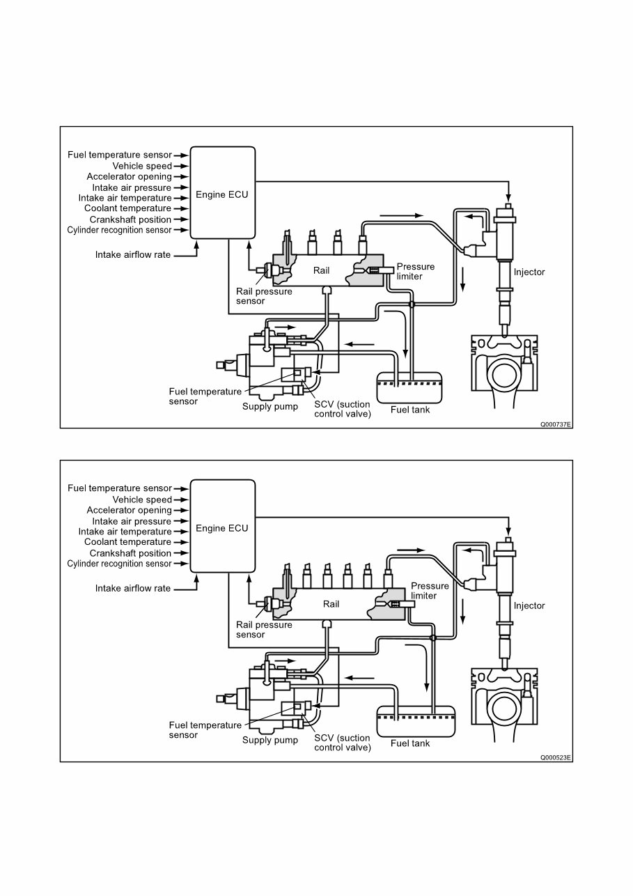
B. Comparison to the Conventional System
-4-
2-2. Outline of System
A. Composition
The common rail system consists primarily of a supply pump, rail, injectors, and engine ECU.
a. 4HK1
b. 6HK1
-5-
B. Operation
a. Supply pump (HP3/HP4)
The supply pump draws fuel from the fuel tank, and pumps the high pressure fuel to the rail. The quantity of fuel dis-
charged from the supply pump controls the pressure in the rail. The SCV (Suction Control Valve) in the supply pump
effects this control in accordance with the command received from the ECU.
b. Rail
The rail is mounted between the supply pump and the injector, and stores the high pressure fuel.
c. Injector (G2 type)
This injector replaces the conventional injection nozzle, and achieves optimal injection by effecting control in accordance
with signals from the ECU. Signals from the ECU determine the length of time and the timing in which current is applied
to the injector.
This in turn, determines the quantity, rate and timing of the fuel that is injected from the injector.
d. Engine ECU
The engine ECU calculates data received from the sensors to comprehensively control the injection quantity, timing and
pressure, as well as the EGR (exhaust gas recirculation).
2-3. Fuel System and Control System
A. Fuel System
This system comprises the route through which diesel fuel flows from the fuel tank to the supply pump, via the rail, and
is injected through the injector, as well as the route through which the fuel returns to the tank via the overflow pipe.
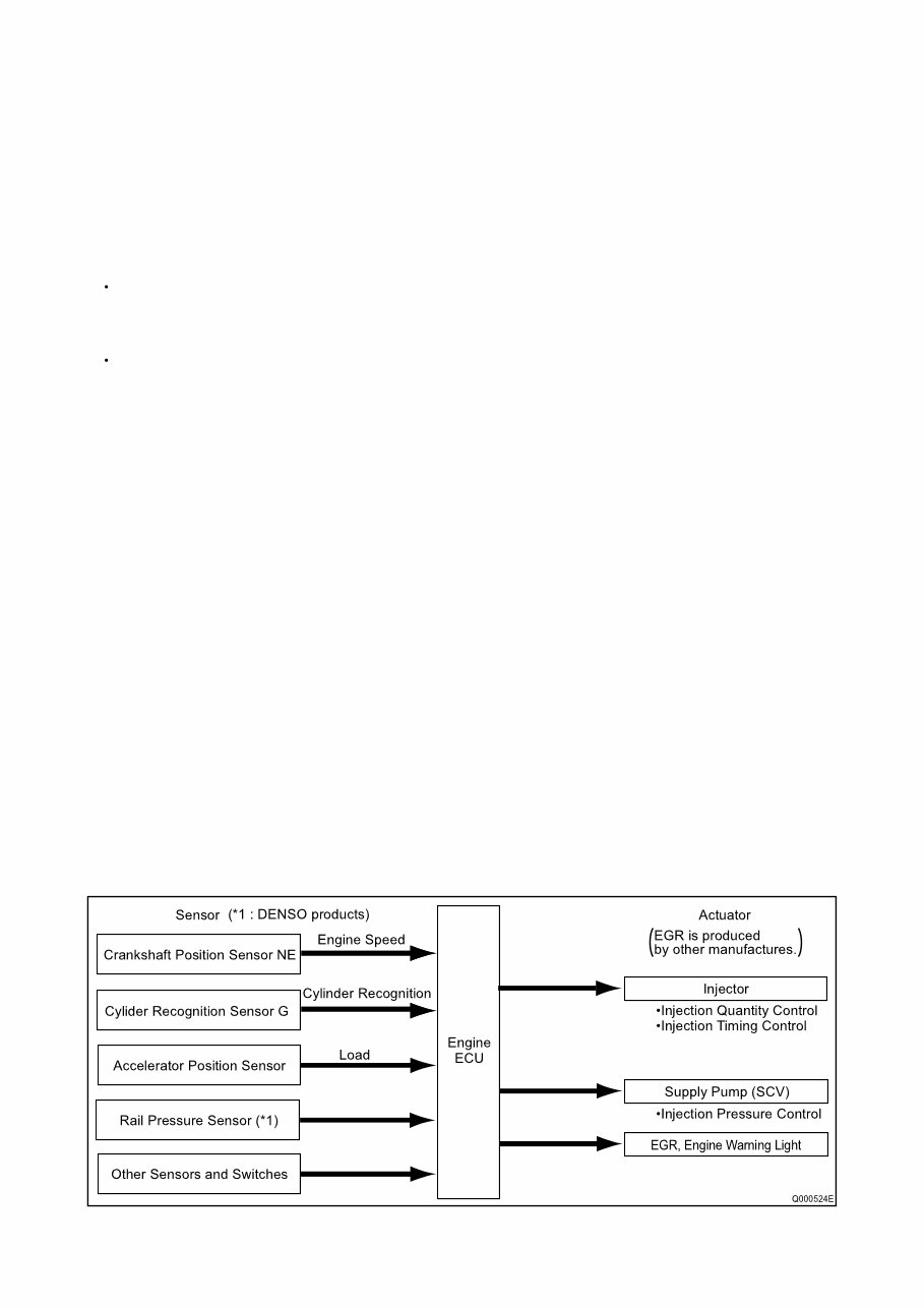
B. Control System
In this system, the engine ECU controls the fuel injection system in accordance with the signals received from various
sensors. The components of this system can be broadly divided into the following three types: (a.) Sensors; (b.) Engine
ECU; and (c.) Actuators.
a. Sensors
Detect the engine and driving conditions, and convert them into electrical signals.
b. Engine ECU
Performs calculations based on the electrical signals received from the sensors, and sends them to the actuators in order
to achieve optimal conditions.
c. Actuators
Operate in accordance with electrical signals received from the ECU. Injection system control is undertaken by electron-
ically controlling the actuators. The injection quantity and timing are determined by controlling the length of time and the
timing in which the current is applied to the TWV (Two-Way Valve) in the injector. The injection pressure is determined
by controlling the SCV (Suction Control Valve) in the supply pump.
-6-
3. Construction and Operation
3-1. Description of Main Components
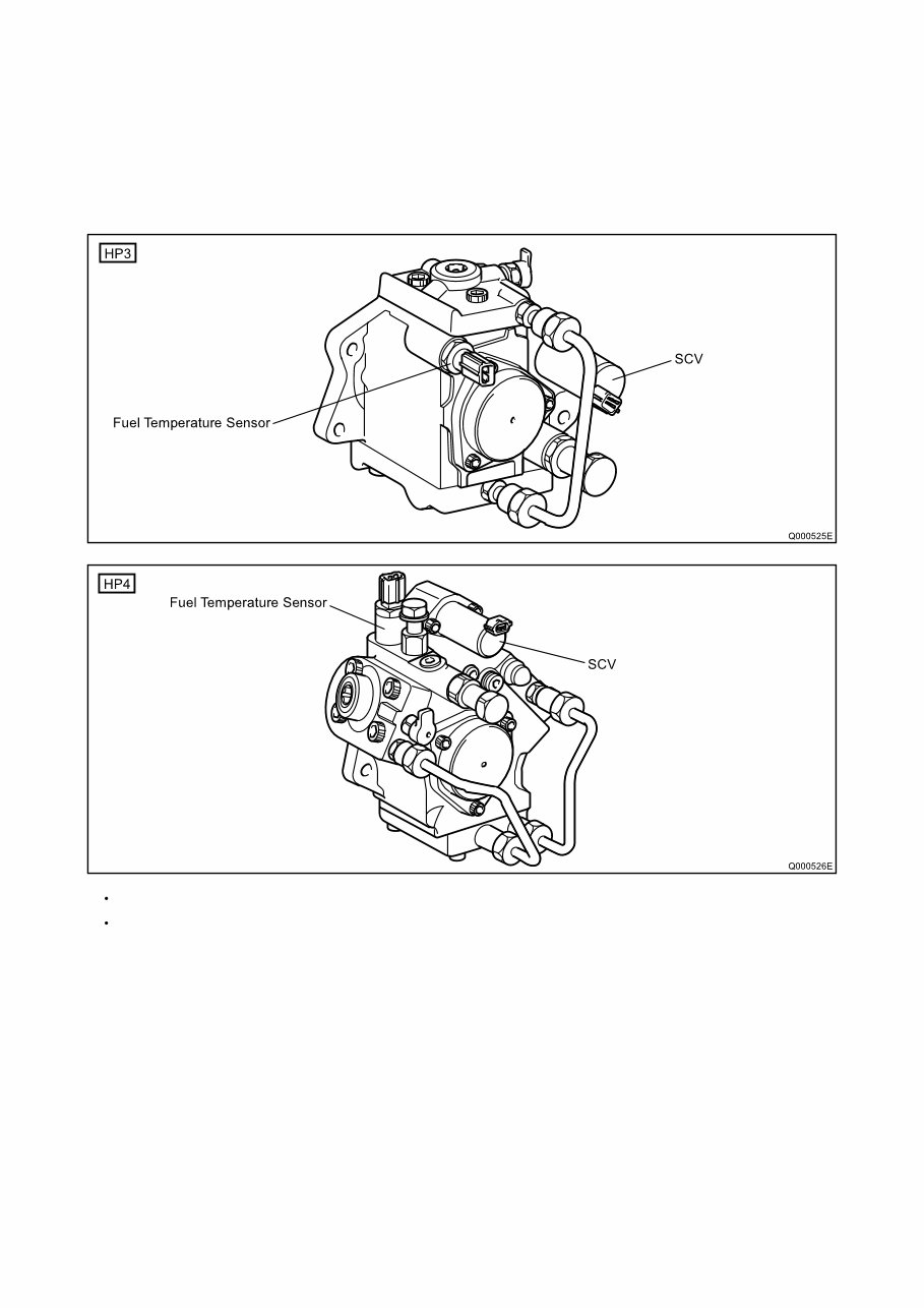
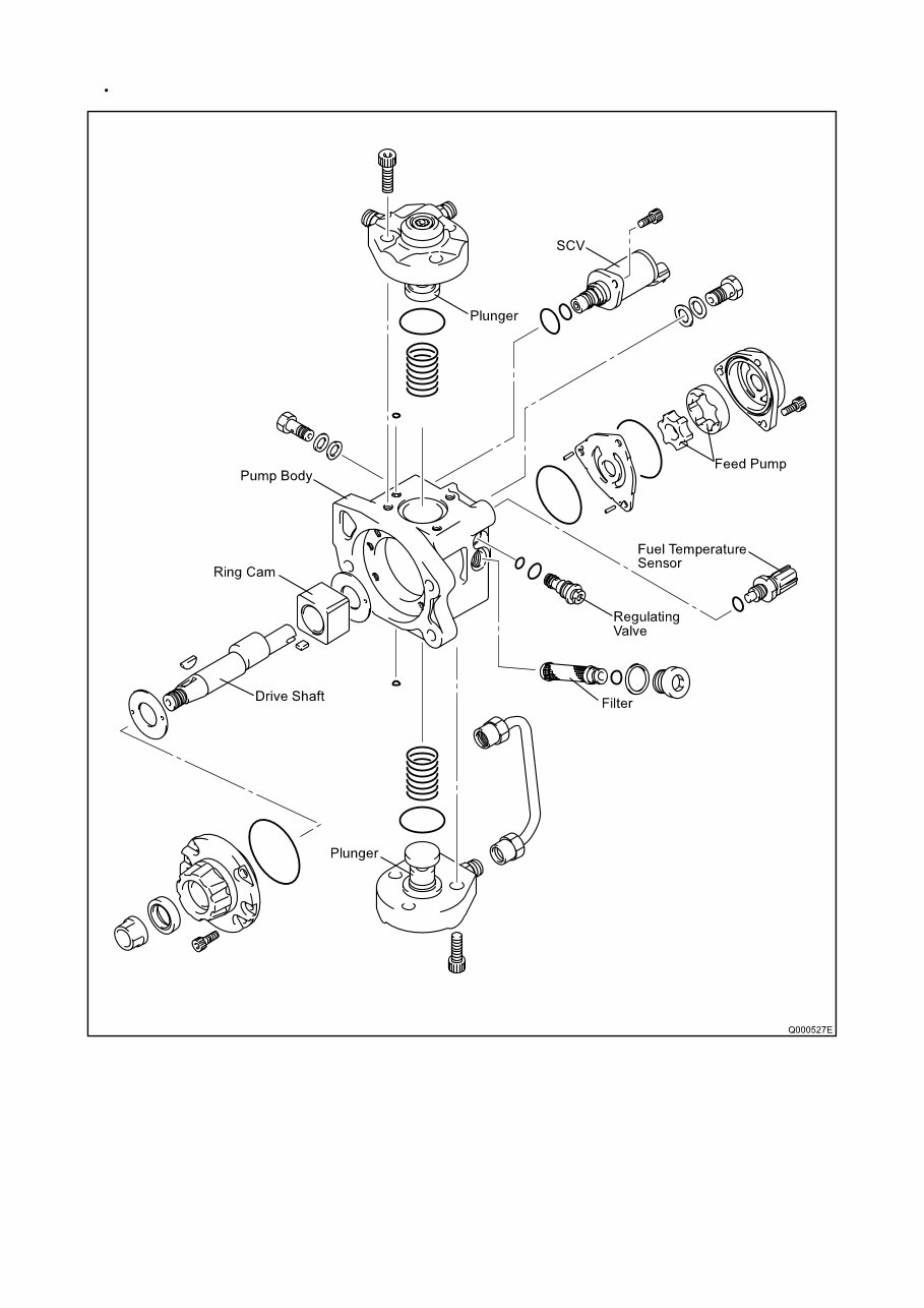
A. Supply Pump (HP3, HP4)
a. Outline
The supply pump consists primarily of the pump body (cam shaft, ring cam, and plungers), SCV (Suction Control Valve),
fuel temperature sensor, and feed pump.
The two plungers for HP3 or the three plungers for HP4 are positioned vertically on the outer ring cam for compactness.
The engine drives the supply pump at a ratio of 1:1. The supply pump has a built-in feed pump (trochoid type), and draws
the fuel from the fuel tank, sending it to the plunger chamber.
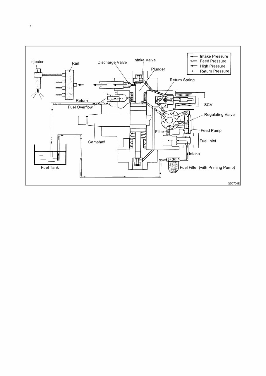
-7-
The internal camshaft drives the two plungers, and they pressurize the fuel sent to the plunger chamber and send it to
the rail. The quantity of fuel supplied to the rail is controlled by the SCV, using signals from the engine ECU. The SCV is
a normally opened type (the intake valve opens during de-energization).
-8-
Development: HP3
You're Reading a Preview
What's Included?
Fast Download Speeds
Online & Offline Access
Access PDF Contents & Bookmarks
Full Search Facility
Print one or all pages of your manual
$28.99
Viewed 64 Times Today


Secure transaction
What's Included?
Fast Download Speeds
Online & Offline Access
Access PDF Contents & Bookmarks
Full Search Facility
Print one or all pages of your manual
$28.99
Get the Denso New Common Rail System for ISUZU 4HK1 / 6HK1 Type Engine Injection Pump Service Manual. This manual, with a publication ID of 00400056E, is available in English and was published in February 2004. It consists of 48 pages and provides essential technical information for professional mechanics and DIY enthusiasts.


