

2003 IAME Parilla 125cc 125 Leopard TAG Engine Service & Repair Manual
What's Included?
Fast Download Speeds
Online & Offline Access
Access PDF Contents & Bookmarks
Full Search Facility
Print one or all pages of your manual
ZZZHXURNDUWGH
MAN-016 D
125cc LEOPARD TaG engine
2003
ASSEMBLY INSTRUCTIONS
and
USER MANUAL
18/10/02 mod. C
ZZZHXURNDUWGH

ZZZHXURNDUWGH
18/10/02 mod. C MAN-016 D 1
INDEX
GENERAL DESCRIPTION OF THE "LEOPARD" ENGINE
CHARACTERISTICS OF THE "LEOPARD" ENGINE – OPERATIONAL LIMITS
1- Contents of the packing
2- Motor identification Number
3- Preparation and installation of the engine on the chassis
3.1 Install the water cooling system
3.2 Exhaust header assembly
3.3 Preparation and installation of the motor-mount
3.4 Install the carburetor
3.5 Install the engine on the chassis
3.6 Install the clutch cover with H.T. coil
3.7 Installation and connection of the power pack box
3.8 Electrical connections on the engine
3.9 Installation of the intake silencer
3.10 Install the exhaust
4- GASOLINE and OIL
5- Carburetor Adjustment guide
6- Starting and stopping the engine
7- Engine break-in
8- Inlet silencer
9- Exhaust system
10- Centrifugal clutch
11- Instructions for the assembly/disassembly of the clutch
12- Battery
13- Spark plug and thermal degree
14- Choice of the best sprocket ratio
15- Scheduled maintenance
16- Troubleshooting
17- Engine and accessories preservation
Attachments: - Fastener Torque Table
- Wiring diagram
Page
1
2
3
4
5
5
9
9
10
12
13
14
15
18
19
20
21
22
22
22
23
23
25
26
27
28
31
32
33
34
35
ZZZHXURNDUWGH

ZZZHXURNDUWGH
18/10/02 mod. C MAN-016 D 1
GENERAL DESCRIPTION OF THE "LEOPARD" ENGINE
This engine of the "TaG" series (Touch and Go) has been expressly designed and
developed for the powering of karts for hobby racing on closed tracks, destined for this
specific purpose. When designing this new line of engines, the technical solutions already
adopted for the high performance engines were used, in order to guarantee the highest
reliability of components, when the operating limitations are respected.
The motor is a single cylinder using the two stroke principle.
The cylinder and the crankcase are in aluminium alloy.
The pressed in liner is made of centrifugated cast iron, fully machined to guarantee the
best possible stability.
The head is separated from the cylinder and secured by studs.
The crankshaft is built and supported by two ball-bearings. The crankshaft is of steel alloy,
hardened and tempered , as is the connecting rod which runs on roller bearings.
The igniton includes a 4 pole stator/rotor with integral pick-up, an H.T. coil and an
electronic unit with micro-processor (Power-Pack), complete with wiring harness.
The main features of the ignition are:
- During the start of the engine, the power-pack activates a booster which increases the
spark energy to facilitate the starting of the engine.
- The ignition system permits, through the electronic unit, the onboard battery recharging
during the normal use of the engine.
- The spark is generated also without a battery: it is therefore possible, in case of
emergency, to start the engine with an external starter unit.
The engine has an integrated electric starter; by pushing the green start button the starter
activates a bendix type gear which engages the starter ring assembled on the clutch.
The engine is provided with an automatic dry centrifugal clutch with low maintenance and
with interchangeable sprocket.
The carburetor is a diaphragm Tillotson carburetor with integral fuel pump, filter and all
position mounting capability.
The battery (12 V- 7.2Ah) is a sealed, no maintenance battery and is supplied already
preassembled in the Power Pack support box which can be easily adapted to all existing
chassis.
The exhaust, included in the supply, is already tuned for the best possible performance.
The engine is supplied with a kit which includes the radiator, the pump, water hoses and
whatever necessary for the assembly on the kart.
ZZZHXURNDUWGH

ZZZHXURNDUWGH
18/10/02 mod. C MAN-016 D 2
CHARACTERISTICS OF THE "LEOPARD" ENGINE - OPERATIONAL LIMITS
1. The characteristics of the engine are the following :
• Cycle: OTTO / 2 stroke
• Original cubic capacity: 123.7 cc
• Original bore: 54.00 mm
• Max. theoretical bore: 54.28 mm
• Stroke: 54.00 mm
• Lubrication : Fuel-Oil mix
• Induction: Reed valve
• Carburetor: Membrane , Tillotson
• Cooling : water
• Ignition: Digital / 4 poles with internal rotor
• Battery charge: With integral generator
• Electric start: 12V/0.30 Kw
• Clutch: Automatic, dry, centrifugal
2. OPERATIONAL LIMITS:
• Max. RPM : 15000 RPM
• Min. waterTemperature: 45°c
• Max. water Temperature : 90°c
ATTENTION:
Never exceed the above limits, no obligation of IAME exists in case the above
limits are exceeded.
ZZZHXURNDUWGH

ZZZHXURNDUWGH
18/10/02 mod. C MAN-016 D 3
1- CONTENT OF THE PACKING
Each Leopard engine is delivered with the under shown accessories:
-125 cc LEOPARD-
TaG engine
EXHAUST
• Flexible 1
• Spring For Flexible 3
• Exhaust Fiber Strip 1
• Exhaut Header 1
• Exhaust Muffler 1
INDUCTION
• Tillotson Carburetor 1
• Intake Silencer 1
• Intake Silencer Support 1
• Accelerator Cable Bracket 1
ELECTRICAL
• Battery 12 V 1
• Battery Support 1
• Battery Strap 1
• Battery Clamps 2
• Power Pack Box with Harness 1
• Plastic Fixing Clamps 8
• NGK BR 10 EG Spark Plug 1
• Spark Plug Cap 1
MISCELLANEOUS
• Additional Engine Plate 1
• Water proof cover 1
• Clutch cover with H.T. coil 1
WATER COOLING
• Radiator 1
• Radiator Support Kit 1
• Complete Hose Kit 1
• Pump, complete 1
ZZZHXURNDUWGH

ZZZHXURNDUWGH
18/10/02 mod. C MAN-016 D 4
2- MOTOR IDENTIFICATION NUMBER
The official motor identification number can be found stamped in the lower left part of
the crankcase, next to the electric starter (see fig.) The number normally includes a
letter followed by 4 digits (there can be exceptions in some special cases). Other
numbers stamped on the crankcase or other surfaces of the motor refer to various
manufacturing processes and do not identify the motor.
NOTE:
In case of need for spares and when contacting the IAME Support Centers,
please always refer to the Motor Identification Number and to the motor model.
ZZZHXURNDUWGH
ZZZHXURNDUWGH
18/10/02 mod. C MAN-016 D 5
3- PREPARATION AND INSTALLATION OF THE ENGINE ON THE CHASSIS
NOTE:
In case the engine is supplied already assembled on the chassis, it is at care of the assembler to
follow these instructions. The final customer, in this case, can skip this section and can start
reading from section 4.
Whenever the engine or a component is disassembled, it is necessary to always follow the under
shown instructions for proper reassembly.
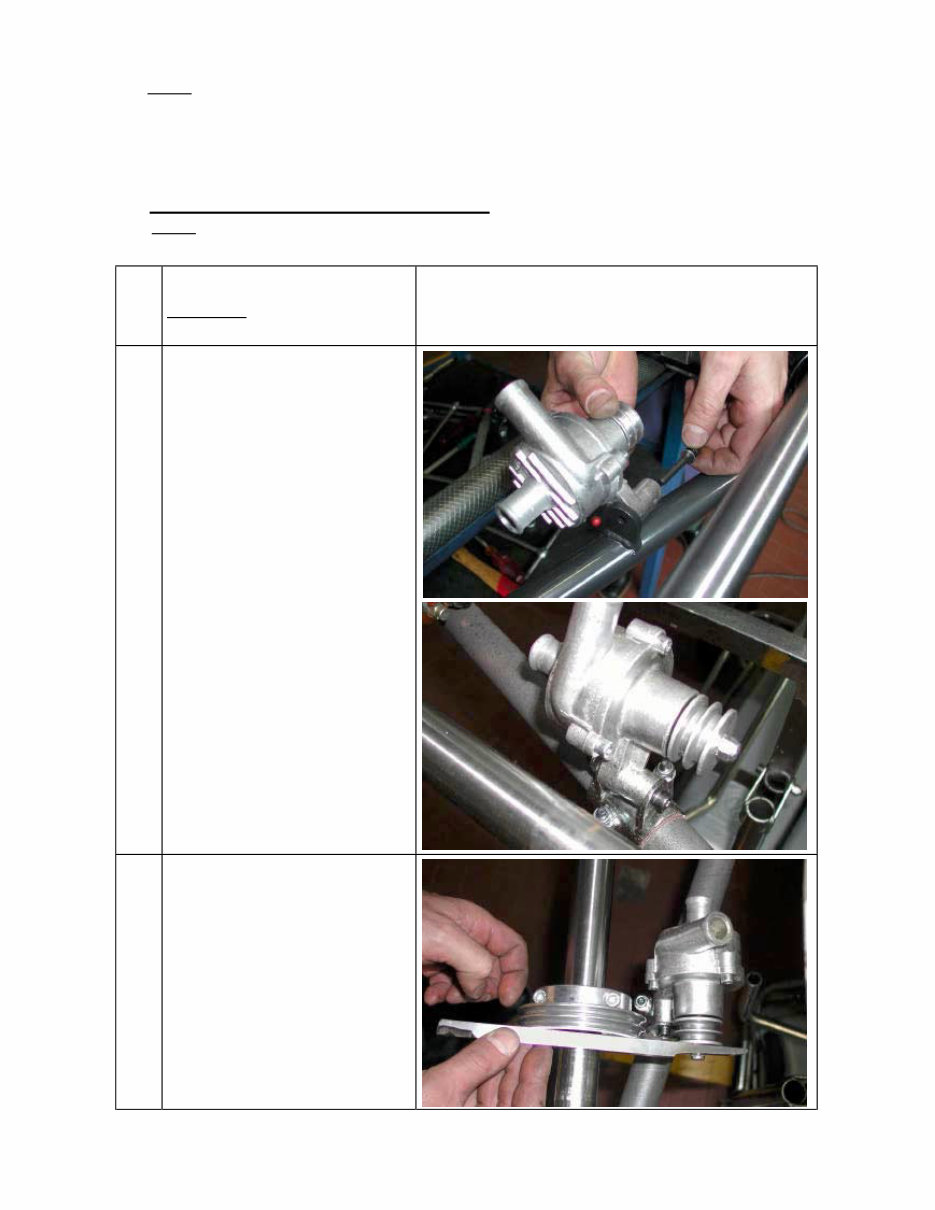
3.1- INSTALL THE WATER COOLING SYSTEM
NOTE:
To install the water pump belts it is necessary to remove the rear axle.
1
REINSTALL THE REAR AXLE AFTER
HAVING INSERTED THE TWO BELTS.
SUGGESTION:
INSTALL OTHER TWO BELTS AS SPARES
AND FIX THEM WITH TAPE TO THE AXLE.
2
INSTALL THE WATER PUMP (1 SCREW M6 X
45 WITH WASHER AND SELF LOCKING
NUT) ON THE PUMP BRACKET ON THE
REAR CROSS RAIL (SEE FIG. 1).
IN CASE THERE IS NO BRACKET FOR THIS
PURPOSE IT I S NECESSARY TO INSTALL
THE PUMP ON REMOVABLE CLAMPS
AVAILABLE IN DIFFERENT DIAMETERS (∅
28/30/32mm) AS ACCESSORIES (SEE FIG.
2).
TIGHTEN BY HAND THE SCREW ON THE
PUMP LETTING IT FREE TO ROTATE FOR
THE TENSIONING OF THE BELTS.
3
INSTALL ON THE AXLE THE DRIVING
PULLEY (n°2 CLAMPS AVAILABLE IN
DIFFERENT DIAMETERS ∅ 30/35/40/50mm)
ALIGNING ITS RACES WITH THE DRIVEN
PULLEY.
TIGHTEN THE CLAMPS WITH TWO SCREWS
M6 X 25.
Fig.1
Fig.2
Fig.3
ZZZHXURNDUWGH
ZZZHXURNDUWGH
18/10/02 mod. C MAN-016 D 6
4
INSTALL THE BELTS AND TENSION (SEE
FIG. 4).
BEFORE INSTALLING THE RADIATOR PREASSEMBLE THE FOLLOWING COMPONENTS
5
INSERT THE RUBBER DAMPENERS INTO
THE FIXING HOLES OF THE RADIATOR AND
INSERT THE SPACERS (SEE FIG. 5).
6
INSERT THE BUSHES INTO THE RADIATOR
SUPPORT BRACKET.
PLACE THE BRACKET BETWEEN THE
RADIATOR FIXINGS (SEE FIG. 6).
Fig.4
Fig.5
RUBBER DAMPENER
SPACER
BUSH
RADIATOR SUPPORT
BRACKET
Fig.6
ZZZHXURNDUWGH
ZZZHXURNDUWGH
18/10/02 mod. C MAN-016 D 7
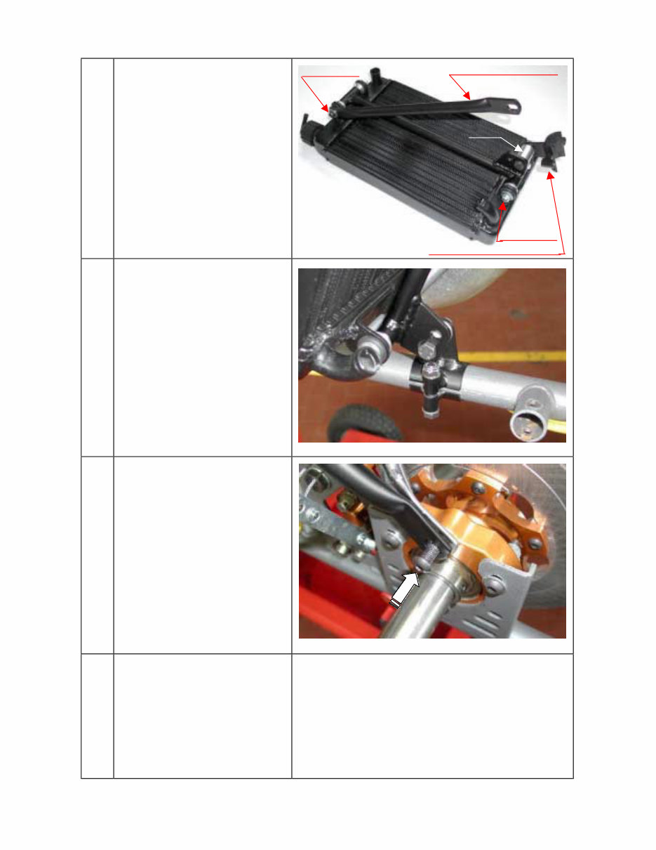
7
FIX THE SUPPORT BRACKET TO THE
RADIATOR, AND ALSO INSERT THE UPPER
SUPPORT BRACKET (SCREWS M6X90 AND
M6X85 WITH NUTS).
PLACE THE RADIATOR LOWER FIXING
CLAMP AND THE SPACER ON THE
RADIATOR SUPPORT BRACKET (SCREW
M8X45 WITH NUT) (SEE FIG. 7).
8
PLACE THE LOWER FIXING CLAMP ON THE
CHASSIS SIDE RAIL (BRAKE SIDE) (N°2
SCREWS M8X45 WITH NUTS) TIGHTEN THE
BOLTS BY HAND (SEE FIG. 8).
9
PLACE THE RADIATOR SO THAT THE HOLE,
ON THE UPPER RADIATOR BRACKET, AND
ONE OF THE UPPER HOLES ON THE
BEARING SUPPORT BOX, MATCH (SEE
FIG. 9).
ONCE YOU FIND THE CORRECT POSITION,
TIGHTEN ALL THE BOLTS
10
THE KIT INCLUDES THREE RUBBER
HOSES.
CONNECT THE FIRST HOSE TO THE
FITTING ON THE RADIATOR INLET AND THE
FITTING ON THE ENGINE OUTLET, TIGHTEN
WITH STEEL CLAMPS (SEE FIG.10).
Fig.7
UPPER SUPPORT BRACKET
RADIATOR LOWER FIXING CLAMP
SPACER
Fig.8
Fig.9
SCREW M6X90
SCREW M6X85
ZZZHXURNDUWGH
ZZZHXURNDUWGH
18/10/02 mod. C MAN-016 D 8
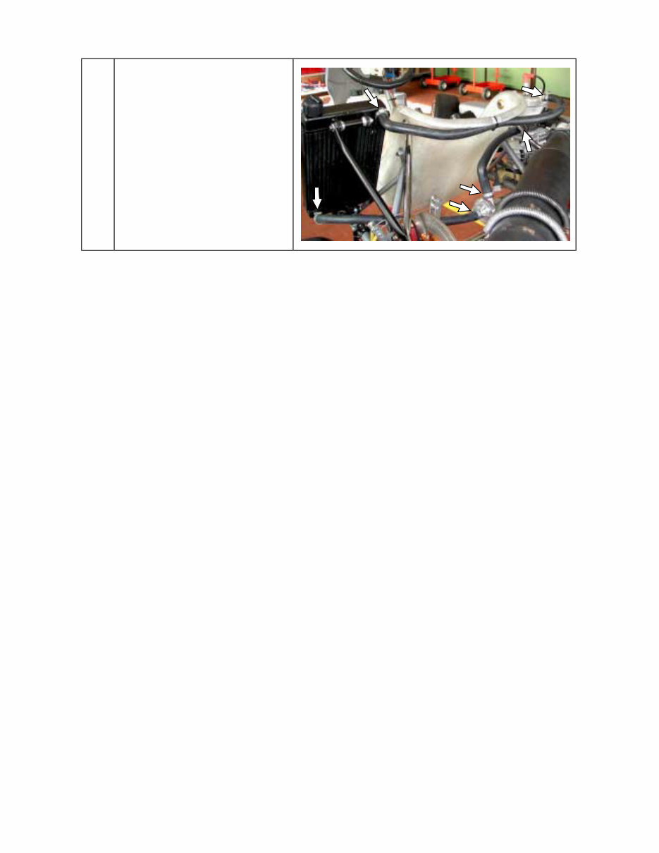
11
CONNECT THE SECOND HOSE BETWEEN
THE FITTINGS ON THE RADIATOR OUTLET
AND THE PUMP INLET.
CONNECT THE THIRD HOSE BETWEEN
THE FITTINGS ON THE PUMP OUTLET AND
THE ENGINE INLET (SEE FIG. 10).
TIGHTEN WITH STEEL CLAMPS.
BEFORE STARTING THE ENGINE FOLLOW THESE RECOMMENDATIONS:
• Unscrew the cap on the radiator and loosen the breather plug on the engine head.
• Fill the radiator until the water comes out from the plug on the head (there is no air in
the system now) and the radiator is completely filled. Tighten the cap (the system
contains appr. 1 lt. of water).
• It is advisable to put a small cup to recover water from the breather on the cap in
case of boiling water.
• After the engine run-in, check the water level in the radiator and top up if
necessary.
Fig.10
ZZZHXURNDUWGH
You're Reading a Preview
What's Included?
Fast Download Speeds
Online & Offline Access
Access PDF Contents & Bookmarks
Full Search Facility
Print one or all pages of your manual
$28.99
Viewed 49 Times Today


Secure transaction
What's Included?
Fast Download Speeds
Online & Offline Access
Access PDF Contents & Bookmarks
Full Search Facility
Print one or all pages of your manual
$28.99
For those in need of comprehensive assembly instructions and user guidance, the "Leopard" engine manual is an invaluable resource. Whether you're a professional mechanic or a DIY enthusiast, this manual provides detailed insights into the "Leopard" engine's characteristics and operational limits.
- Contents of the packing
- Motor identification Number
- Preparation and installation of the engine on the chassis
- Install the water cooling system
- Exhaust header assembly
- Preparation and installation of the motor-mount
- Install the carburetor
- Install the engine on the chassis
- Install the clutch cover with H.T. coil
- Installation and connection of the power pack box
- Electrical connections on the engine
- Installation of the intake silencer
- Install the exhaust
- GASOLINE and OIL
- Carburetor Adjustment guide
- Starting and stopping the engine
- Engine break-in
- Inlet silencer
- Exhaust system
- Centrifugal clutch
- Instructions for the assembly/disassembly of the clutch
- Battery
- Spark plug and thermal degree
- Choice of the best sprocket ratio
- Scheduled maintenance
- Troubleshooting
- Engine and accessories preservation
Additionally, the manual includes attachments such as the Fastener Torque Table and Wiring diagram, making it an all-encompassing guide for working with the "Leopard" engine.


