

Hino N04C engine workshop manual
What's Included?
Fast Download Speeds
Online & Offline Access
Access PDF Contents & Bookmarks
Full Search Facility
Print one or all pages of your manual

NAME SECTION
GENERAL 0
TROUBLESHOOTING 1
ENGINE OVERHAUL 2
FUEL SYSTEM 3
COOLING SYSTEM 4
LUBRICATION SYSTEM 5
STARTING SYSTEM 6
CHARGING SYSTEM 7
TURBOCHARGER SYSTEM 8
APPENDIX 9
12
12
13
14
15
16
17
18
19
20
21
E
SECTION INDEX


0-1
0
1
2
3
4
5
6
7
8
9
10
11
12
13
14
15
16
17
18
19
20
21
E
GENERAL
Page
SPECIFICATIONS .................................................. 0-2
ENGINE EXTERIOR VIEWS .................................. 0-3
ENGINE PERFORMANCE CURVES ..................... 0-4
HOW TO USE THIS MANUAL ............................... 0-5
EXPLANATION METHOD ......................................... 0-5
TERMINOLOGY ....................................................... 0-6
ABBREVIATIONS .................................................... 0-7
OPERATING TIPS .................................................. 0-8
POINTS FOR WHICH SPECIAL CARE
MUST BE TAKEN ................................................... 0-8
GENERAL INSTRUCTIONS ...................................... 0-8
ELECTRICAL PARTS INSPECTION ......................... 0-11
BOLT & NUT TIGHTENING TORQUES ............... 0-13
BOLT STRENGTH CLASS IDENTIFICATION
METHOD AND TIGHTENING TORQUE .................. 0-13
PRECOATED BOLTS (BOLTS WITH SEAL
LOCK AGENT COATING ON THREADS) ......... 0-16
SI UNITS ............................................................... 0-16
HANDLING FIPG (LIQUID GASKETS) ................ 0-17
0-2 0-2
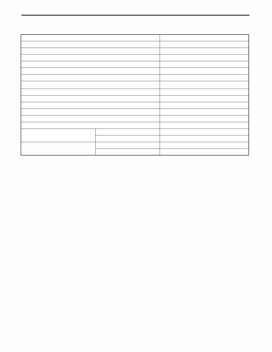
SPECIFICATIONS
Engine model N04C
Type Diesel
Cycle 4 cycle
Number and arrangement of cylinders In-line 4 cylinder, longitudinally mounted
Combustion chamber type Direct injection
Valve mechanism OHV gear drive
Bore × stroke mm (in.) 104.0 × 118.0 (4.09 × 4.65)
Total displacement cm
3
(in
3
.)
4009 (244.6)
Compression ratio 18.0
Minimum fuel Consumption when fully loaded g/kw·h (g/ps·h)/rpm 217 (160)/1600
No-load maximum speed rpm 2290 to 2390
Idle speed rpm 800 to 850
Engine dimensions (Length × width × height) mm (in.) 887 × 716 × 751 (34 × 21 × 29)
Weight (Oil included) kg (lb) 396 (873)
Intake valve open/close interval
Open BTDC 14°
Close ABDC 42°
Exhaust valve open/close interval
Open BBDC 53°
Close ATDC 17°
0-3
0
1
2
3
4
5
6
7
8
9
10
11
12
13
14
15
16
17
18
19
20
21
E
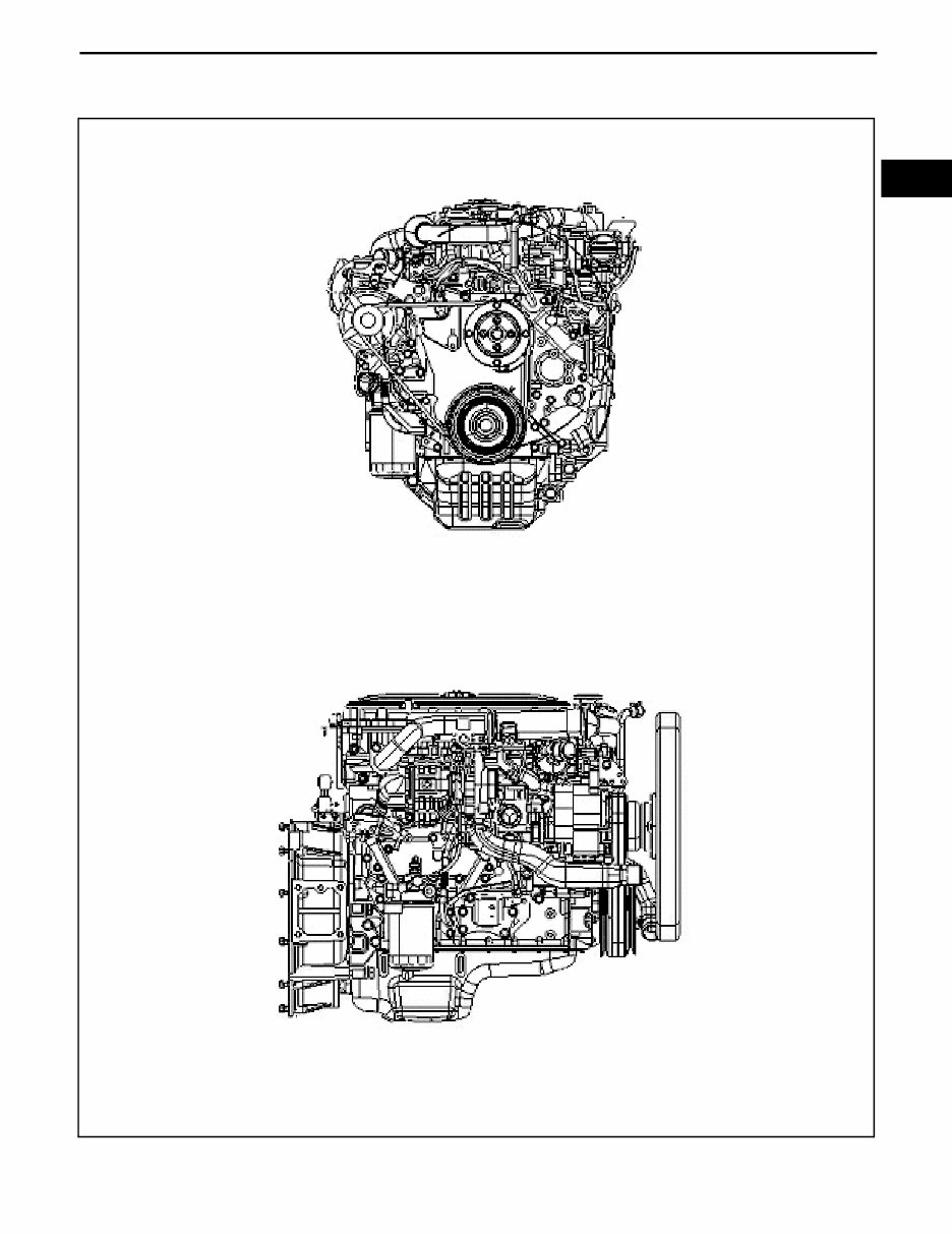
ENGINE EXTERIOR VIEWS
0-4 0-4
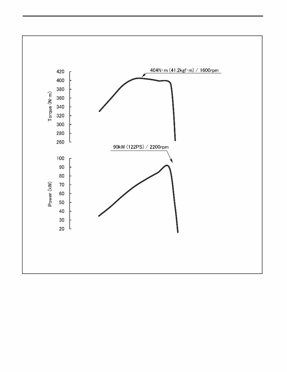
ENGINE PERFORMANCE CURVES
0-5
0
1
2
3
4
5
6
7
8
9
10
11
12
13
14
15
16
17
18
19
20
21
E
HOW TO USE THIS MANUAL
EXPLANATION METHOD
1. Operating procedure
(1) Operating procedures are described using either pattern A or pattern B.
Pattern A: Each step of the operation is explained with its own illustration.
Pattern B: The entire operation is indicated by step numbers in one illustration, followed by cautions, notes,
and "Point Operations".
Example of pattern B
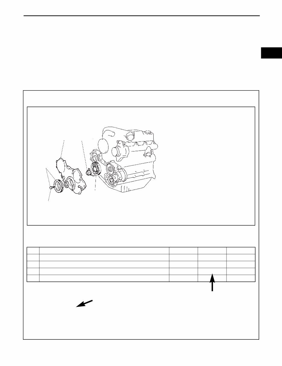
DISASSEMBLY·INSPECTION·REASSEMBLY
Tightening torque unit → T = N·m (kgf·cm) [ft·lbf]
Disassembly·Reassembly Procedure
The reassembly procedure is the reverse of the disassembly procedure.
Point Operations
[Point 1]
Inspection:
Measure the backlash.
Standard: 0.05 mm (0.0020 in.)
[Point 2]
Reassembly: Install the rotor in the position shown in the illustration.
No. Item Disassembly Inspection Reassembly
1 Crank pulley W/ set bolt
2 Timing gear cover
3 Idle gear No.1 [Point 1]
4 Oil pump ASSY [Point 2]
• The numbers may partially be
omitted in the illustration.
• In the case where a part for
which the tightening torque is
specified is not shown in the
illustration, the name of the
part will be listed inside the
illustration frame.
T = 274.59 ~ 370.69 (2800 ~ 3780) [202.6 ~ 273.5]
1
2 4
3
Explanation of operation
point with illustration Operations that have a following explanation

0-6 0-6
1. How to read component figures
(1) The component figures use the illustration in the parts
catalog for the vehicle model. Please refer to the catalog
to check the part name.
2. Matters omitted from this manual
(1) This manual omits descriptions of the following jobs, but
perform them in actual operation:
(a) Cleaning and washing of removed parts as required
(b) Visual inspection (partially described)
TERMINOLOGY
Warning:
Items that may lead to an injury to either the operator or another person, and items and operation point
switch, if not followed, may lead to an injury or accident.
Caution:
Items that must not be performed because doing so will result in damage to the vehicle or it's components,
and items in the operation to which special attention should be paid.
Note:
Supplemental explanations for performing the operation easily.
Standard: Value showing the allowable range in inspection or adjustment.
Limit: The maximum or minimum value allowed in inspection or adjustment.
(Example)
Parts catalog
FIG number
3201

0-7
ABBREVIATIONS
Reference symbol Original word Meaning
RH Right Hand Right hand side
LH Left Hand Left hand side
FR Front Front
RR Rear Rear
STD Standard
This refers to the part size used by the maker at the time of assembly
being the standard size.
O/S Over Size
For parts that do not engage well anymore due to wear from long use,
or repeated disassembly, by replacing the part that is engaged by a part
of slightly larger dimensions, it's corresponding part can be reused.
These parts that have larger dimensions than STD, and are referred to
as O/S.
U/S Under Size
As with the O/S parts, by replacing the engaging part with one that has
a smaller hole, it's corresponding part can be reused. These parts that
have smaller dimensions than STD, and are referred to as U/S.
ATDC After Top Dead Center After the top dead center point of the piston in the cylinder.
BTDC Before Top Dead Center Before the top dead center point of the piston in the cylinder.
IN Intake Refers to the intake system.
EX Exhaust Refers to the exhaust system.
SST Special Service Tool Special service tool
T Torque Tightening torque
ASSY Assembly
A part that consists of two or more single parts or sub-assembled parts
that have been assembled together into an integrated whole.
SUB/ASSY Sub Assembly
A part in which two or more parts are joined together by welding,
casting, riveting etc.
W/ With/
The following items are attached.
(Example: W/ washer ... With a washer attached)
LWR Lower Lower
0-8 0-8
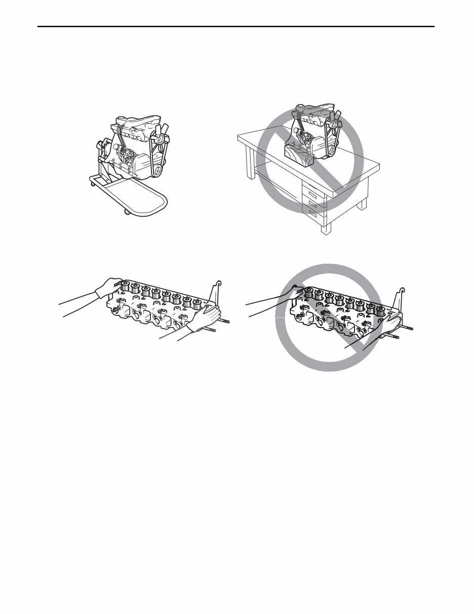
OPERATING TIPS
POINTS FOR WHICH SPECIAL CARE MUST BE TAKEN
1. Always set the engine on an engine stand for carrying out assembly and disassembly of an engine. Never
operate on a workbench or on the floor as this is dangerous.
2. When handling and moving the cylinder head ASSY or the cylinder block, always wear gloves and do not use
your bare hands.
GENERAL INSTRUCTIONS
1. For safe operation
(1) Wear the correct safety gear (cap, safety goggles, gloves, safety shoes).
(2) To prevent burns, do not touch the radiator, muffler or exhaust pipe directly after stopping the engine.
(3) Do not put your clothing or tools near to the rotating part when the engine is turning.
(4) When the engine is not on, always have the engine switch OFF, and remove the starter key.
2. Preparation for disassembly
(1) Prepare general tools, SSTs, measuring instruments, lubricant and parts that cannot be reused.
(2) When disassembling a complex part, put imprints and match marks in places that will not effect the function
of the part in order to facilitate easy reassembly.
3. Prevention of entry of foreign bodies
Foreign bodies such as dust, sand and metal pieces inside the engine cause faults to occur.
(1) Thoroughly remove sand and mud etc. sticking to the engine exterior.
(2) Protect disassembled parts from dust with a plastic cover or similar.
You're Reading a Preview
What's Included?
Fast Download Speeds
Online & Offline Access
Access PDF Contents & Bookmarks
Full Search Facility
Print one or all pages of your manual
$36.99
Viewed 57 Times Today


Secure transaction
What's Included?
Fast Download Speeds
Online & Offline Access
Access PDF Contents & Bookmarks
Full Search Facility
Print one or all pages of your manual
$36.99
This workshop manual for the Hino N04C engine provides comprehensive information for car repair. It includes the following sections:
- General: Specifications, engine exterior views, engine performance curves, how to use this manual, explanation method, terminology, abbreviations, operating tips, points for which special care must be taken, general instructions, electrical parts inspection, bolt & nut tightening torques, bolt strength class identification method and tightening torque, precoated bolts, SI units, handling FIPG (liquid gaskets)
- Troubleshooting: Troubleshooting
- Engine Overhaul: Used SSTs, engine accessories, removal and installation, cylinder head, disassembly, inspection and reassembly, timing gear, disassembly, inspection and reassembly, cylinder block, disassembly, inspection and reassembly, engine turn-up, coolant inspection, engine oil inspection, battery electrolyte inspection, V belt inspection and adjustment, idle speed inspection, no-load maximum governed speed inspection, compression pressure inspection, diesel smoke density inspection, valve clearance inspection, EGR valve assy inspection
- Fuel System: Precaution, fuel filter, removal, inspection and installation, injection (supply) pump, removal, inspection and installation, common rail, removal, inspection and installation, fuel injector, removal, inspection and installation, venturi assy, removal, inspection and installation
- Cooling System: Inspection of functions, coolant replacement, water pump assy removal and installation, thermostat removal, inspection and installation
- Lubrication System: Used SSTs, lubrication system, inspection of functions, oil pump replacement, oil filter replacement, oil cooler assy replacement
- Starting System: Starter motor assy removal, inspection and installation, preheating system, inspection of preheating timer, replacement of glow plug, inspection of glow plug
- Charging System: Inspection of functions, alternator assy removal and installation
- Turbocharger System: Turbocharger assy removal and installation
- Appendix: SST list, service standards, tightening torque for each part
This manual is valuable for both professional mechanics and DIY enthusiasts seeking detailed engine repair information.


