

GM 6.2 Liter Diesel Engine service training manual
What's Included?
Fast Download Speeds
Online & Offline Access
Access PDF Contents & Bookmarks
Full Search Facility
Print one or all pages of your manual
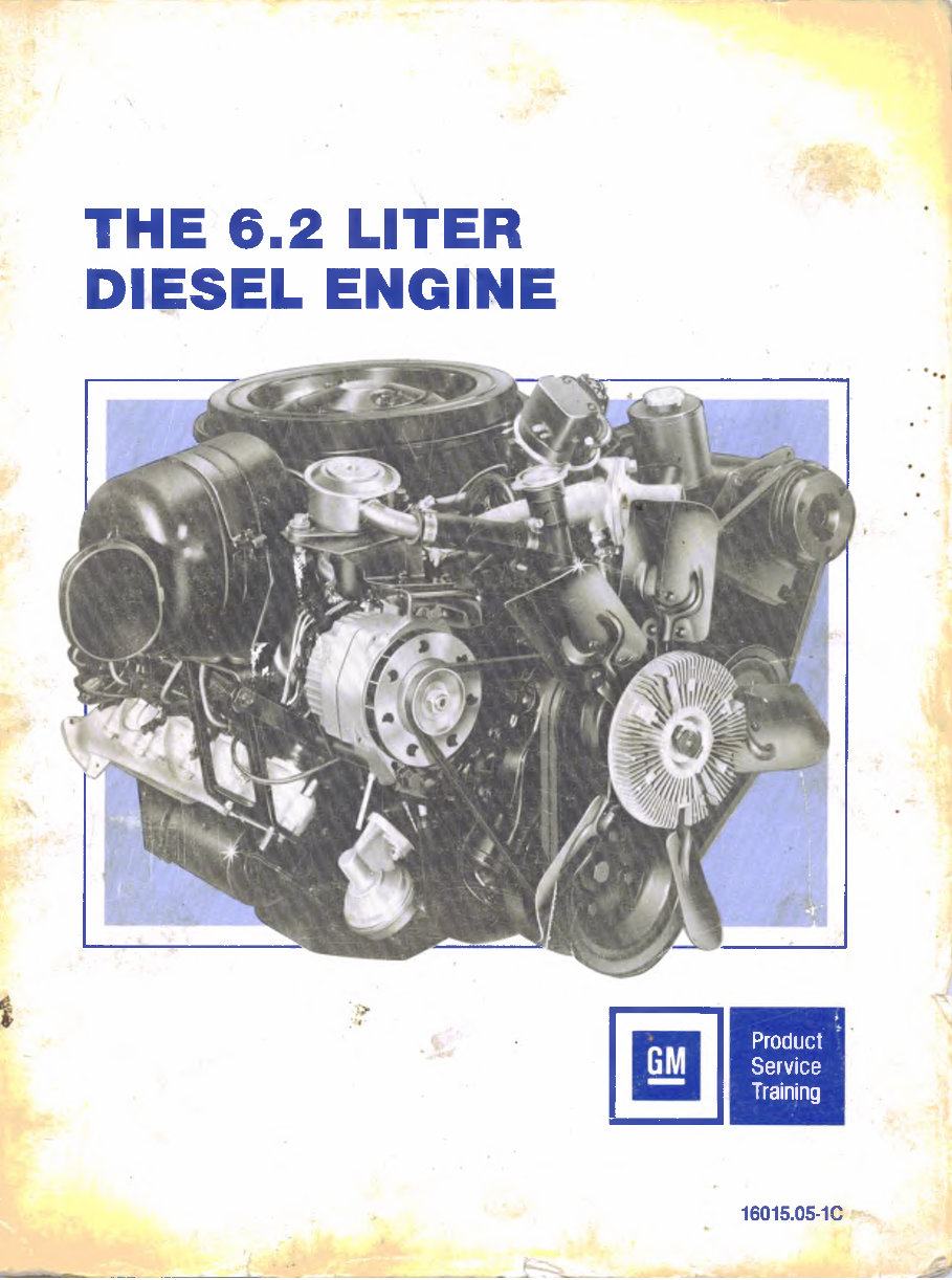
THE 6.2 LITER
DIESEL ENGINE
Product
Service
Training
16015.05-1C
6.2 Liter Diesel Engine
Foreword
This booklet is supplied by GM Product Service Training to GM dealer service personnel upon their
completion of the subject course conducted at GM Training Centers.
While this booklet will serve as an excellent review of the extensive program presented in the training
center session, it is not intended to substitute for the various service manuals normally used on the job.
The range of specifications and variation in procedures between carlines and models requires that the
division service publications be referred to, as necessary, when performing these operations.
All information contained in this booklet is based on the latest data available at the time of publication
approval. The right is reserved to make product or publication changes, at any time, without notice. This
booklet, or any portion thereof, may not be reproduced without written consent of GM Product Service
Training, General Motors Corporation.
Portions of this book were produced using information provided by Detroit Diesel Allison Division,
Stanadyne Diesel Systems and Robert Bosch Corporation.
— NOTE —
Many of the words and terms in this section are explained in the
“glossary” section at the back of this book. If the meaning of a new or confusing
word or term isn’t clear, always take the time to look it up.
Table of Contents
Page
1. General Information and Maintenance ................1-1
General Description ................................................. 1-1
Engine Identification ............................................... 1-2
LH6 (C) Engine Specifications ............................... 1-4
General Engine Description ............................... 1-4
Technical Engine Specifications ...................... 1-4
LL4 (J) Engine Specifications ............................... 1-6
General Engine Description ............................... 1-6
Technical Engine Specifications ...................... 1-6
Torque Specifications ........................................ 1-9
Reference Information ........................................ 1-11
6.2 Liter Diesel Service Information ...................... 1-16
Operation In Snow (Diesel Engines) ............... 1-16
Starting the Diesel Engine ................................. 1-16
Emergency “Jump Starting” ............................. 1-18
Diesel Maintenance .............................................1-18
Engine Oil Additives .............................................1-19
Diesel Engine Oil Usage ....................................1-19
Used Lube Oil Analysis Warning Values ......... 1-20
2. Engine Systems and Construction ...................... 2-1
Engine Design Features ........................................ 2-1
Cylinder Case ........................................................2-2
6.2L Valve Train ................................................... 2-3
1985 and Later Rocker Arm Assembly ............. 2-4
Roller Hydraulic Lifters ...................................... 2-5
Roller Lifter Wear — Diesel Engines ............... 2-10
Valve Lifter Diagnosis ........................................ 2-10
Cylinder Head ........................................................2-12
Pre-Combustion Chambers ............................... 2-13
Broken Glow Plug T ip .......................................... 2-13
Servicing Cylinder Head and Gasket ............... 2-13
V-8 Diesel Head Gasket Leakage .................... 2-13
V-8 Diesel Head Gasket Installation
Checklist ............................................................ 2-14
Leaking Cylinder Head G asket ........................ 2-15
Valve Stem Clearance ........................................ 2-18
Valve Spring Tension .......................................... 2-18
Inspection (Timing C hain) ................................. 2-18
Valve Guide Bores ............................................... 2-19
Valve Seats ............................................................ 2-19
Page
Valves ..................................................................... 2-19
Valve Stem Oil Seal/Or Valve Spring ................2-19
Piston Construction (Figure 2-17) .................... 2-20
Piston Selection ................................................... 2-21
Piston Inspection ................................................. 2-22
Piston Related Cylinder Case Operations ... .2-23
Rod and Piston ..................................................... 2-24
Crankshaft ............................................................ 2-24
Crankshaft Rear Main S e a l ............................... 2-25
Upper Rear Main Seal Repair ............................. 2-26
Lower Rear Main Oil Seal Replacement ......... 2-27
Main Bearings ................................................... . 2-28
Connecting Rod Bearings ................................. 2-30
Rod Assembly ..................................................... 2-30
Torsional Damper 6.2L ........................................ 2-31
Camshaft .............................................................. 2-31
Camshaft Bearings ............................................ 2-32
Flywheel ................................................................ 2-33
Front Cover ...................... ..................................... 2-34
Exhaust M anifolds ...............................................2-34
Lubrication System ............................................ 2-35
Engine and Transmission Oil Cooler
Diagnosis, All M odels ................................... 2-37
Oil Filler Tube ....................................................... 2-38
Vacuum Pum p ..................................................... 2-40
Cooling System ................................................... 2-45
Cooling System Diagnosis ............................... 2-46
Fan Clutch Diagnosis ........................................ 2-48
Water Pump .......................................................... 2-50
Radiator ................................................................ 2-51
Cooling System Schematic ............................... 2-55
1985 Cooling System .......................................... 2-55
Low Coolant Lamp Inoperative ........................ 2-57
Low Coolant Lamp “On” All the Tim e ............. 2-58*
Base Engine Troubleshooting ........................... 2-60
3. Charge Air System ................................................... 3-1
Air Flow To Combustion Cham ber ...................... 3-1
4. Fuel System . . : ............................................ .......... 4-1
4A. Low Pressure Fuel Delivery System ............. 4-1
Fuel System Components ............................... 4-1
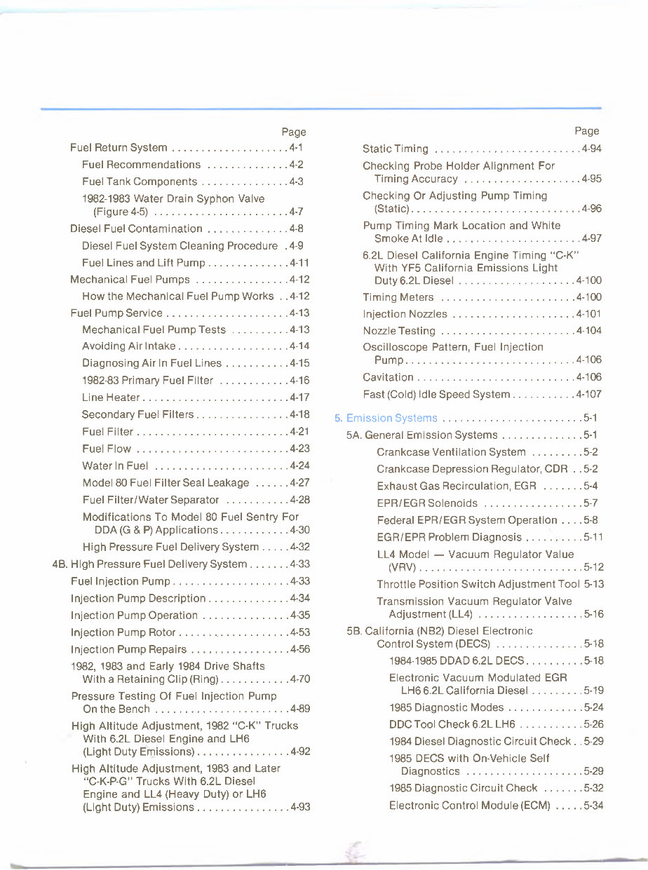
Page
Fuel Return System .......................................... 4-1
Fuel Recommendations ............................. 4-2
Fuel Tank Components ............................... 4-3
1982-1983 Water Drain Syphon Valve
(Figure 4-5) ................................................. 4-7
Diesel Fuel Contamination ............................. 4-8
Diesel Fuel System Cleaning Procedure .4-9
Fuel Lines and Lift Pump ............................. 4-11
Mechanical Fuel P um ps ................................. 4-12
How the Mechanical Fuel Pump Works .. 4-12
Fuel Pump Service ............................................ 4-13
Mechanical Fuel Pump T ests .................... 4-13
Avoiding Air Intake ........................................ 4-14
Diagnosing Air In Fuel Lines ...................... 4-15
1982-83 Primary Fuel F ilte r ........................ 4-16
Line Heater ..................................................... 4-17
Secondary Fuel Filters ................................. 4-18
Fuel Filter ........................................................4-21
Fuel F lo w ........................................................4-23
Water In Fuel ................................................. 4-24
Model 80 Fuel Filter Seal Leakage ........... 4-27
Fuel Filter/Water Separator ...................... 4-28
Modifications To Model 80 Fuel Sentry For
DDA (G & P) Applications ........................ 4-30
High Pressure Fuel Delivery System ......... 4-32
4B. High Pressure Fuel Delivery System ............. 4-33
Fuel Injection Pump .......................................... 4-33
Injection Pump Description ............................. 4-34
Injection Pump Operation ............................... 4-35
Injection Pump Rotor ........... ............................ 4-53
Injection Pump Repairs ....................................4-56
1982, 1983 and Early 1984 Drive Shafts
With a Retaining Clip (Ring) ........................ 4-70
Pressure Testing Of Fuel Injection Pump
On the Bench ................................................. 4-89
High Altitude Adjustment, 1982 “C-K” Trucks
With 6.2L Diesel Engine and LH6
(Light Duty Emissions) ................................. 4-92
High Altitude Adjustment, 1983 and Later
“C-K-P-G” Trucks With 6.2L Diesel
Engine and LL4 (Heavy Duty) or LH6
(Light Duty) Emissions ................................. 4-93
Static T im in g ..................................................... 4-94
Checking Probe Holder Alignment For
Timing Accuracy ........................ ................. 4-95
Checking Or Adjusting Pump Timing
(Static) .............................................................. 4-96
Pump Timing Mark Location and White
Smoke At Idle ................................................. 4-97
6.2L Diesel California Engine Timing “C-K”
With YF5 California Emissions Light
Duty 6.2L D iesel .......................................... 4-100
Timing Meters ................................................. 4-100
Injection Nozzles ............................................ 4-101
Nozzle Testing ................................................. 4-104
Oscilloscope Pattern, Fuel Injection
Pump .............................................................. 4-106
Cavitation .......................................................... 4-106
Fast (Cold) Idle Speed System ...................... 4-107
5. Emission Systems ................................................... 5-1
5A. General Emission Systems ............................. 5-1
Crankcase Ventilation System .................. 5-2
Crankcase Depression Regulator, CDR . .5-2
Exhaust Gas Recirculation, EGR ............. 5-4
EPR/EGR Solenoids ....................................5-7
Federal EPR/EGR System Operation ... .5-8
EGR/EPR Problem Diagnosis .................... 5-11
LL4 Model — Vacuum Regulator Value
(VRV) ............................................................ 5-12
Throttle Position Switch Adjustment Tool 5-13
Transmission Vacuum Regulator Valve
Adjustment (LL4) ...................................... 5-16
5B. California (NB2) Diesel Electronic
Control System (DECS) ............................... 5-18
1984-1985 DDAD 6.2L DECS .................... 5-18
Electronic Vacuum Modulated EGR
LH6 6.2L California Diesel .................. 5-19
1985 Diagnostic Modes ...........................5-24
DDC Tool Check 6.2LLH6 ...................... 5-26
1984 Diesel Diagnostic Circuit Check .. 5-29
1985 DECS with On-Vehicle Self
Diagnostics .......................................... 5-29
1985 Diagnostic Circuit C heck ............. 5-32
Electronic Control Module (ECM) ......... 5-34
Page
Page
1984 California6.2L Diesel ECM Usage 5-35
1985 California 6.2L Diesel ECM Usage 5-35
1984 ECM Check 6.2L(LH6) .................... 5-38
Engine Speed Sensor (R PM ) .................. 5-44
Exhaust Gas Recirculation Control
(EGR) ....................................................... 5-48
EPR Valve ................................................... 5-50
Desired EGR Pressure Calculation ... .5-51
EPR Solenoid Electrical Check
(1984 & 1985) .......................................... 5-56
EPR Vacuum Check (1984 & 1985) ......... 5-58
Strain Gage MAP Sensor ........................ 5-63
MAP Sensor ............................................... 5-64
Throttle Position Sensor, TPS ................5-70
1984 & 1985 TPS C h e c k ...........................5-70
Throttle Position Sensor, TPS
Adjustment ............................................ 5-76
Torque Converter Clutch Control ......... 5-78
Cold Advance Circuit, C A C .................... 5-84
6. Electrical System ..................................................... 6-1
Starting System ....................................................... 6-1
Starter M o to r ....................................................... 6-1
Batteries ................................................................ 6-4
Block Heater .......................................................... 6-4
Glow Plugs ............................................................ 6-4
Glow Plug Design Considerations .................. 6-6
Electro-Mechanical Thermal Controller ......... 6-8
Electronic Module Glow Plug Controller ......... 6-9
System Operation, (Engine Cold-Pre-Glow) . .6-12
General Glow Plug System Diagnosis ............... 6-14
Tools for Diagnosis ............................................ 6-14
Preliminary Checks ............................................ 6-14
Glow Plug Controller and Advanced
Engine Timing ................................................. 6-15
Preliminary Diagnosis With Ammeter ............. 6-16
1982-1984 6.2L Diesel Glow Plug
System Diagnosis .......................................... 6-17
Installation of Glow Plug System Inhibit
Switch ................................................................ 6-23
D-Truck (CUCV) Military 6.2L (LL4) PTC
Glow Plug System ...............................................6-24
The D-Truck (CUCV) System is
Composed o f ............................................... 6-24
System Operation, D-Truck ...........................6-26
Glow Plug System Troubleshooting Procedure,
D-Truck ...................................................................6-26
1985 6.2L (LH6/LL4) Glow Plug
Control System, CKGP-Truck ........................ 6-34
1983 Diesel G-Truck Engine Run-On, 6.2L
Diesel with Base Engine Warning Lights . .6-37
6.2L Diesel Drive Belts, 1982-1984 C/K/P/G
Truck With 6.2L Diesel Engine ...................... 6-38
7. Diagnosis ...................................................................7-1
General/Mechanical Diagnosis .......................... 7-1
General Diagnosis Charts ................................. 7-1
General Diagnosis Conditions ........................ 7-15
Smoke Diagnosis Principles ............................. 7-15
Black Smoke Diagnosis Chart ...........................7-17
White Smoke Diagnosis Chart ...........................7-18
Rough Idle Diagnosis ...........................■£?......... 7-19
Glow Plug Resistance Procedure .................... 7-23
Rough Idle/Performance Diagnosis
Conditions ....................................................... 7-24
M.P.G. Diagnosis Principles ............................... 7-24
Fuel System Diagnosis ...................................... 7-26
Diagnosis of Fuel System Conditions ............. 7-27
Brakes Diagnosis — Diesel Vehicles ............. 7-29
Diesel Engine Oil Leak Diagnosis .................... 7-29
RTV Sealer and Gasket E lim inator ...................... 7-30
Explanation of Abbreviations ...........................7-33
Procedure 1. Checking Cranking Speed ............. 7-33
Procedure 2. Checking for Adequate
Supply of Fuel to Injection Pump .................... 7-34
Procedure 3. Measuring Housing Pressure
and Transfer Pressure ........................................ 7-35
Procedure 4. Checking for Air Leaks .................... 7-38
Air Leak Diagnosis ...............................................7-38
Procedure 5. Causes of Underrun or Stalling ... 7-39
Procedure 6. Checking For Sticky or Stuck
Advance Mechanism .......................................... 7-40
8. Glossary .....................................................................8-1
Page

1. General Information
and Maintenance
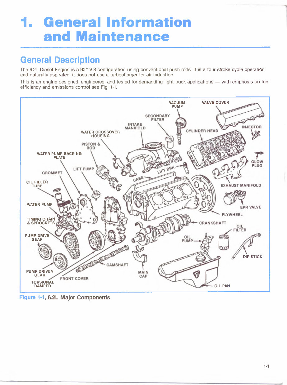
General Description
The 6.2L Diesel Engine is a 90° V-8 configuration using conventional push rods. It is a four stroke cycle operation
and naturally aspirated; it does not use a turbocharger for air induction.
This is an engine designed, engineered, and tested for demanding light truck applications — with emphasis on fuel
efficiency and emissions control see Fig. 1-1.
VACUUM
PUMP
VALVE COVER
WATER CROSSOVER
HOUSING
WATER PUMP BACKING
PLATE
OIL FILLER
TUBE
WATER PUMP
TIMING CHAIN
& SPROCKETS
PUMP DRIVE
GEAR
DIP STICK
PUMP DRIVEN
GEAR
TORSIONAL
DAMPER OIL PAN
Figure 1-1, 6.2L Major Components
1-1
1. General Information and Maintenance
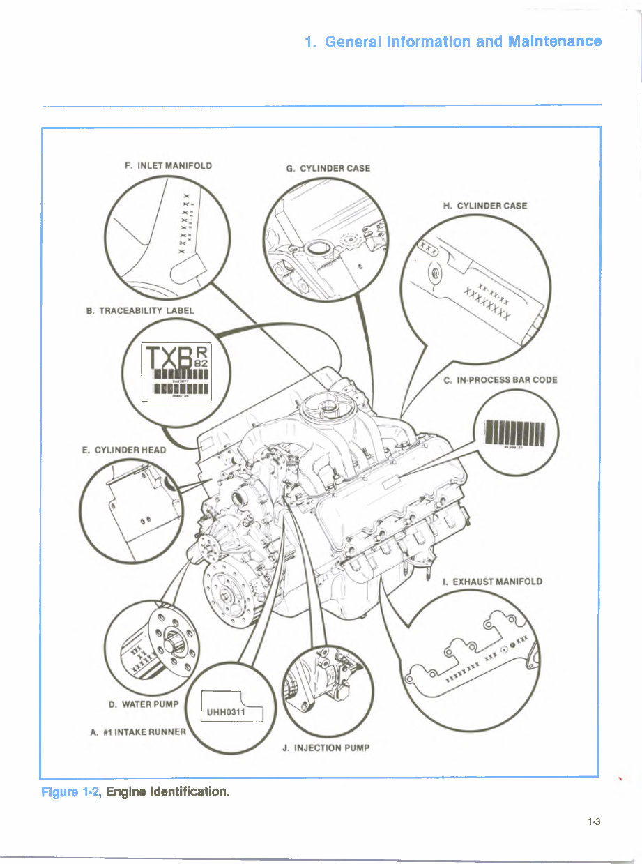
Engine Identification
A. #1 CYLINDER INTAKE RUNNER — A steel stamp placed on the engine part way through the assembly
process, is located on the block under the #1 inlet runner. The stamp identifies the broadcast code, which
essentially defines the engine configuration, plus the month and date of build. A typical marking would be a
broadcast code UHH0311, indicating the engine was built on March 11.
B. THE TRACEABILITY LABEL glued to the engine contains two bar codes. The #1 code would include the
number 10, indicating an “engine”, plus the broadcast code, which could be 1 of 37 codes presently released (i.e.,
UHH). The #2 bar code would contain a computer letter, plus component identification, component manufacturing
location, Julian date and a serial number. As an example, the first piece of information on the bar code would be a
letter “T”, which is simply for programming in the computer. The next information would be a number 10 to define
the component as being an engine. The next bit of information would be the letter “R” to signify the product was
made at the Moraine Engine Plant and the Julian date follows, which for March the 11th, the 70th day of the year,
would be 070. After the date the serial number of the engine appears, which is started new for each broadcast code
at the beginning of the Model Year. For each of the 36 broadcast codes there will be a separate set of serial
numbers starting with #1 for the 1983 M.Y. and continuing until the last product of the current Model Year is
manufactured.
BROADCAST CODE SUFFIX CODES
UHH 03 11
/ 1 t
SUFFIX MONTH DAY
T — 1982 D - 1985
U — 1983 H — 1986
F — 1984 J — 1987
C. ENGINE PLANT IN-PROCESS BAR CODE IDENTIFICATION — Top of left-hand rocker cover consists of
numerical codes to identify type of engine and in-plant serial number for internal use only. Cannot be used to
reference engine in communication with the engine plant.
D. WATER PUMP — Cast identification on front of water inlet tube, depressed cast numbers. Cast date alpha and
3 numbers. Pattern number alpha and 1 number.
E. CYLINDER HEAD — Drill points on end of head to identify internal machining changes and type of head.
F. INLET MANIFOLD — Cast identification on top of #4 inlet runner (right side—rear). Raised cast numbers. Cast
date and shift underneath.
G. CYLINDER CASE — Casting plant pattern identification. Raised cast in clock to show time of casting. Pattern
number in valley under inlet manifold.
H. CYLINDER CASE — Cast identification on top of left-hand flywheel housing surface. Raised cast numbers
with cast date underneath. Pattern number to right of cast number. (CFD) Central Foundry Defiance.
I. EXHAUST MANIFOLD — Cast identification on outside face. Raised cast numbers. Pattern number and date
cast clock casting plant ID.
J. INJECTION PUMP — Printed plate riveted to left side of pump body. Model number and serial number.
K. (TPS) 6 DIGIT IDENTIFIER -
Throttle
Position
Switch
1-2
1. General Information and Maintenance
Figure 1-2, Engine Identification.
1-3
1. General Information and Maintenance
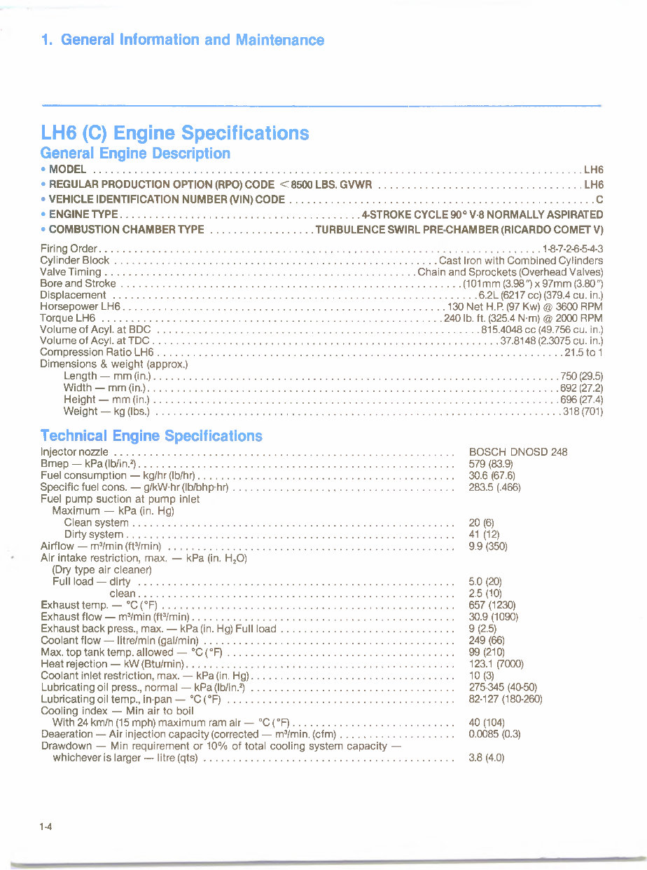
LH6 (C) Engine Specifications
General Engine Description
• MODEL ...................................................................................................................................................................................... LH6
• REGULAR PRODUCTION OPTION (RPO) CODE <8500 LBS. G V W R ........................................................................... LH6
• VEHICLE IDENTIFICATION NUMBER (VIN) CODE ................................................................................................................. C
• ENGINE TYPE ......................................................................................... 4-STROKE CYCLE 90° V-8 NORMALLY ASPIRATED
• COMBUSTION CHAMBER T Y P E ...................................... TURBULENCE SWIRL PRE CHAMBER (RICARDO COMET V)
Firing Order.................................................................................................................................................................... 1-8-7-2-6-5-4-3
Cylinder Block ........................................................................................................................ Cast Iron with Combined Cylinders
Valve Timing ................................................................................................................... Chain and Sprockets (Overhead Valves)
Bore and Stroke .............................................................................................................................. (101mm (3.98") x 97mm (3.80")
Displacement ....................................................................................................................................... 6.2L (6217 cc) (379.4 cu. in.)
Horsepower LH 6 ........................................................................................................................ 130 Net H.P. (97 Kw) @ 3600 RPM
Torque LH6 .............................................................................................................................. 240 lb. ft. (325.4 N-m) @ 2000 RPM
Volume of Acyl. at B D C ........................................................................................................................815.4048 cc (49.756 cu. in.)
Volume of Acyl. at T D C ................................................................................................................................ 37.8148 (2.3075 cu. in.)
Compression Ratio L H 6 ....................................................................................................................................................... 21.5 to 1
Dimensions & weight (approx.)
Length — mm (in.)....................................................................................................................................................... 750 (29.5)
Width — mm (in.)......................................................................................................................................................... 692(27.2)
Height — mm (in.) ....................................................................................................................................................... 696 (27.4)
Weight — kg (lbs.) ....................................................................................................................................................... 318(701)
Technical Engine Specifications
Injector nozzle .............................................................................................................................. .... BOSCH DNOSD 248
Bmep — kPa (lb/in.2) ..................................................................................................................... .... 579 (83.9)
Fuel consumption — kg/hr (lb/hr)............................................................................................... .... 30.6 (67.6)
Specific fuel cons. — g/kW-hr (lb/bhp h r) .................................................................................. .... 283.5 (.466)
Fuel pump suction at pump inlet
Maximum — kPa (in. Hg)
Clean system ............................................................................................................................ 20 (6)
Dirty system .......................................................................................................................... .... 41(12)
Airflow — m3/min (ft3/min) .......................................................................................................... .... 9.9 (350)
Air intake restriction, max. — kPa (in. H20)
(Dry type air cleaner)
Full load — dirty ..................................................................................................................... .... 5.0 (20)
clean ..................................................................................................................... .... 2.5(10)
Exhaust temp. — °C (° F ) ............................................................................................................ .... 657 (1230)
Exhaust flow — m3/min (ft3/min) ................................................................................................. .... 30.9 (1090)
Exhaust back press., max. — kPa (in. Hg) Full lo ad ................................................................ .... 9 (2.5)
Coolant flow — litre/min (gal/min) ............................................................................................. .... 249 (66)
Max. top tank temp, allowed — °C (° F ) .................................................................................... .... 99 (210)
Heat rejection — kW (Btu/min)........................................................................................................ 123.1 (7000)
Coolant inlet restriction, max. — kPa (in. Hg) ........................................................................... .... 10 (3)
Lubricating oil press., normal — kPa (lb/in.2) ........................................................................... .... 275-345 (40-50)
Lubricating oil temp., in-pan — °C ( ° F ) .................................................................................... .... 82-127 (180-260)
Cooling index — Min air to boil
With 24 km/h (15 mph) maximum ram air — °C (°F) ................................................................ 40(104)
Deaeration — Air injection capacity (corrected — m3/min. (cfm ) .......................................... .... 0.0085 (0.3)
Drawdown — Min requirement or 10% of total cooling system capacity —
whichever is larger — litre (q ts ) ............................................................................................. .... 3.8 (4.0)
1-4
You're Reading a Preview
What's Included?
Fast Download Speeds
Online & Offline Access
Access PDF Contents & Bookmarks
Full Search Facility
Print one or all pages of your manual
$39.99
$51.99
Viewed 43 Times Today


Secure transaction
What's Included?
Fast Download Speeds
Online & Offline Access
Access PDF Contents & Bookmarks
Full Search Facility
Print one or all pages of your manual
$39.99
$51.99
This 386-page booklet is provided by GM Product Service Training to GM dealer service personnel upon their completion of the subject course conducted at GM Training Centers.
While this booklet will serve as an excellent review of the extensive program presented in the training center session, it is not intended to substitute for the various service manuals normally used on the job.
The range of specifications and variation in procedures between carlines and models requires that the division service publications be referred to, as necessary, when performing these operations.


