

Ford VSG-411 and 413 service manual
What's Included?
Fast Download Speeds
Online & Offline Access
Access PDF Contents & Bookmarks
Full Search Facility
Print one or all pages of your manual
VSG-4111413
ENGINE
The
SERVICE MANUAL
I uwer...
Worldwide TM
For Engines Produced 1993 and Later
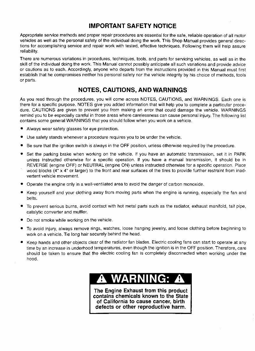
IMPORTANT SAFETY NOTICE
Appropriate service methods and proper repair procedures are essential for the safe, reliable operation of all motor
vehicles as well as the personal safety of the individual doing the work. This Shop Manual provides general direc-
tions for accomplishing service and repair work with tested, effective techniques. Following them will help assure
reliability.
There are numerous variations in procedures, techniques, tools, and parts for servicing vehicles, as well as in the
skill of the individual doing the work. This Manual cannot possibly anticipate all such variations and provide advice
or cautions as to each. Accordingly, anyone who departs from the instructions provided in this Manual must first
establish that he compromises neither his personal safety nor the vehicle integrity by his choice of methods, tools
or parts.
NOTES, CAUTIONS, AND WARNINGS
As you read through the procedures, you will come across NOTES, CAUTIONS, and WARNINGS. Each one is
there for a specific purpose. NOTES give you added information that will help you to complete a particular proce-
dure. CAUTIONS are given to prevent you from making an error that could damage the vehicle. WARNINGS
remind you to be especially careful in those areas where carelessness can cause personal injury. The following list
contains some general WARNINGS that you should follow when you work on a vehicle.
Always wear safety glasses for eye protection.
Use safety stands whenever a procedure requires you to be under the vehicle.
Be sure that the ignition switch is always in the OFF position, unless otherwise required by the procedure.
Set the parking brake when working on the vehicle. If you have an automatic transmission, set it in PARK
unless instructed otherwise for a specific operation. If you have a manual transmission, it should be in
REVERSE (engine OFF) or NEUTRAL (engine ON) unless instructed otherwise for a specific operation. Place
wood blocks (4” x 4” or larger) to the front and rear surfaces of the tires to provide further restraint from inad-
vertent vehicle movement.
Operate the engine only in a well-ventilated area to avoid the danger of carbon monoxide.
Keep yourself and your clothing away from moving parts when the engine is running, especially the fan and
belts.
To prevent serious burns, avoid contact with hot metal parts such as the radiator, exhaust manifold, tail pipe,
catalytic converter and muffler.
60 not smoke while working on the vehicle
To avoid injury, always remove rings, watches, loose hanging jewelry, and loose clothing before beginning to
work on a vehicle. Tie long hair securely behind the head.
Keep hands and other objects clear of the radiator fan blades. Electric cooling fans can start to operate at any
time by an increase in underhood temperatures, even though the ignition is in the OFF position. Therefore, care
should be taken to ensure that the electric cooling fan is completely disconnected when workina under the
hood.
The Engine Exhaust from this product
contains chemicals known to the State
of California to cause cancer, birth
defects or other reproductive harm.
Introduction
In general, this manual covers the servicing of the engine and asso-
ciated standard equipment. In many cases, engines are supplied
with accessories and equipment that are unique to the application. If
service information is ever required on such unique accessories or
equipment it is suggested that Power Products Division/GRI be con-
tacted. The proper information will either be forwarded or the Ser-
vice Technician will be advised where it can be obtained.
The information in this manual is grouped in sections according to
the type of work being performed. The various sections are indi-
cated in the index. In addition, each section is subdivided to include
topics such as diagnosis and testing, cleaning and inspection, over-
haul, removal and installation procedures, disassembly and assem-
bly procedures, and service specifications.
POWER PRODUCTS DIVISION/GRI
The Source for Power...
28333 TELEGRAPH ROAD - #300
Worldwide rev
SOUTHFIELD, MICHIGAN 48034
The descriptions and specifications contained in this manual were in
effect at the time the book was released for printing. Power Products
Division/GM reserves the right to discontinue models at any time, or
change specifications or design, without notice and without incurring
obligation.
NOTE: The recommendations and suggestions contained in this
___ - -- I_ I . . . . . . .I
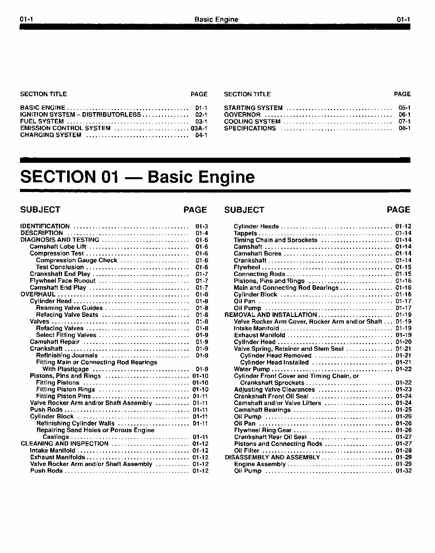
01-l Basic Engine 01-I
SECTION TITLE PAGE SECTION TITLE PAGE
BASICENGINE ....................................... 01-l STARTING SYSTEM .................................. 051
IGNITION SYSTEM - DISTRIBUTORLESS ............... 02-l GOVERNOR ......................................... 06-l
FUEL SYSTEM ....................................... 03-I COOLING SYSTEM ................................... 07-I
EMISSION CONTROL SYSTEM ........................ 03A-1 SPECIFICATIONS .................................... 08-l
CHARGINGSYSTEM . . . . . . . . . . . . . . . . . . . . . . . . . . . . . . . . . 04-l
SECTION 01 - Basic Engine
SUBJECT PAGE
IDENTIFICATION ..................................... 01-3
DESCRIPTION ....................................... 01-4
DIAGNOSIS AND TESTING ............................ 01-6
Camshaft Lobe Lift ................................ 01-6
Compression Test ................................. 01-6
Compression Gauge Check ...................... 01-6
Test Conclusion ................................. 01-6
Crankshaft End Play ............................... 01-7
Flywheel Face Runout ............................. 01-7
Camshaft End Play ................................ 01-7
OVERHAUL .......................................... 01-8
Cylinder Head ..................................... 01-8
Reaming Valve Guides ........................... 01-8
Refacing Valve Seats ............................ 01-8
Valves.. .......................................... 01-8
Refacing Valves ................................. 01-8
Select Fitting Valves ............................. 01-9
Camshaft Repair .................................. 01-9
Crankshaft ........................................ 01-9
Refinishing Journals ............................ 01-9
Fitting Main or Connecting Rod Bearings
With Plastigage ............................... 01-9
Pistons, Pins and Rings ........................... 01-10
Fitting Pistons .................................. 01-l 0
Fitting Piston Rings ............................. 01-10
Fitting Piston Pins ............................... 01-11
Valve Rocker Arm and/or Shaft Assembly ........... 01-11
PushRods ........................................ 01-11
Cylinder Block .................................... 01-11
Refinishing Cylinder Walls ....................... 01-11
Repairing Sand Holes or Porous Engine
Castings ...................................... 01-11
CLEANING AND INSPECTION ......................... 01-l 2
Intake Manifold .................................... 01-I 2
Exhaust Manifolds ................................. 01-l 2
Valve Rocker Arm and/or Shaft Assembly ........... 01-12
PushRods.. ...................................... 01-12
SUBJECT PAGE
Cylinder Heads .................................... 01-12
Tappets ........................................... 01-14
Timing Chain and Sprockets ....................... 01-14
Camshaft ......................................... 01-14
Camshaft Bores ................................... 01-I 4
Crankshaft ........................................ 01-I 4
Flywheel .......................................... 01-l 5
Connecting Rods .................................. 01-l 5
Pistons, Pins and Rings ........................... 01-16
Main and Connecting Rod Bearings ................. 01-16
Cylinder Block .................................... 01-l 6
Oil Pan ........................................... 01-17
Oil Pump ......................................... 01-17
REMOVAL AND INSTALLATION ........................ 01-I 9
Valve Rocker Arm Cover, Rocker Arm and/or Shaft ... 01-19
Intake Manifold .................................... 01-I 9
Exhaust Manifold .................................. 01-l 9
Cylinder Head ..................................... 01-20
Valve Spring, Retainer and Stem Seal ............... 01-21
Cylinder Head Removed ......................... 01-21
Cylinder Head Installed .......................... 01-21
Water Pump ....................................... 01-22
Cylinder Front Cover and Timing Chain, or
Crankshaft Sprockets ............................ 01-22
Adjusting Valve Clearances ........................ 01-23
Crankshaft Front Oil Seal .......................... 01-24
Camshaft and/or Valve Lifters ...................... 01-24
Camshaft Bearings ................................ 01-25
Oil Pump ......................................... 01-26
Oil Pan ........................................... 01-26
Flywheel Ring Gear ................................ 01-26
Crankshaft Rear Oil Seal ........................... 01-27
Pistons and Connecting Rods ...................... 01-27
Oil Filter .......................................... 01-28
DISASSEMBLY AND ASSEMBLY ....................... 01-29
Engine Assembly .................................. 01-29
Oil Pump ......................................... 01-32

01-2 Basic Engine 01-2
BLANK
01-3 Basic Enaine 01-3
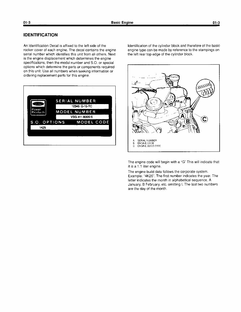
IDENTIFICATION
An Identification Decal is affixed to the left side of the
rocker cover of each engine. The decal contains the engine
serial number which identifies this unit from all others. Next
is the engine displacement which determines the engine
specifications, then the model number and S.O. or special
options which determine the parts or components required
on this unit. Use all numbers when seeking information or
ordering replacement parts for this engine.
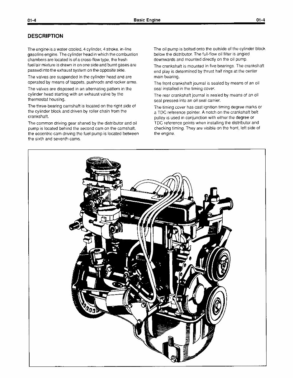
Identification of the cylinder block and therefore of the basic
engine type can be made by reference to the stampings on
the left rear top edge of the cylinder block.
A SERIAL NUMBER
B ENGINE CODE
C ENGINE BUILD DATE
The engine code will begin with a “G” This will indicate that
it is a 1.I liter engine.
The engine build date follows the corporate system.
Example: “4K26”. The first number indicates the year. The
letter indicates the month in alphabetical sequence, A
January, B February, etc. omitting I. The last two numbers
are the day of the month.
01-4
DESCRIPTION
Basic Engine 01-4
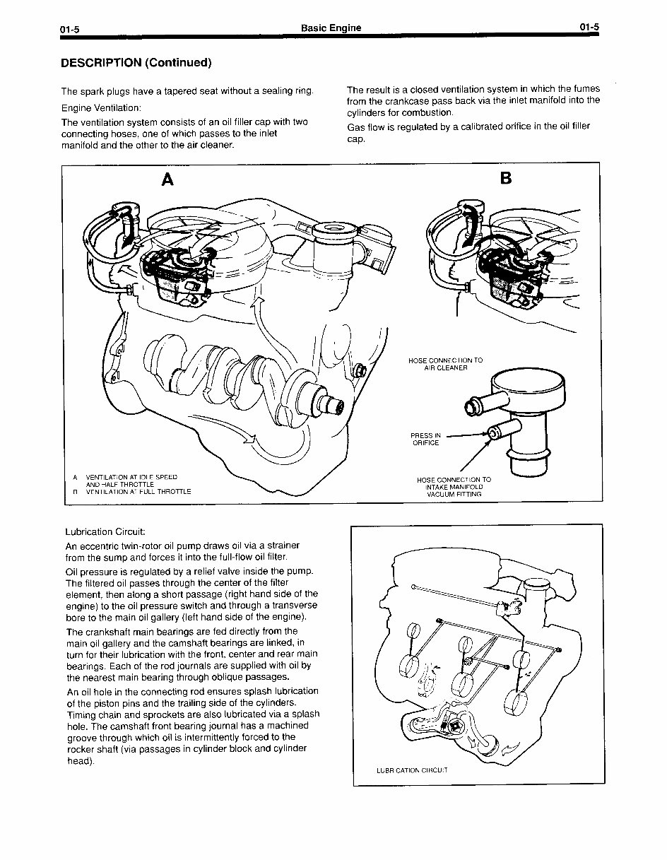
The engine is a water-cooled, 4 cylinder, 4 stroke, in-line
The oil pump is bolted onto the outside of the cylinder block
gasoline engine. The cylinder head in which the combustion
chambers are located is of a cross-flow type, the fresh
fuel/air mixture is drawn in on one side and burnt gases are
passed into the exhaust system on the opposite side.
The valves are suspended in the cylinder head and are
operated by means of tappets, pushrods and rocker arms.
The valves are disposed in an alternating pattern in the
cylinder head starting with an exhaust valve by the
thermostat housing.
The three-bearing camshaft is located on the right side of
the cylinder block and driven by roller chain from the
crankshaft.
The common driving gear shared by the distributor and oil
pump is located behind the second cam on the camshaft,
the eccentric cam driving the fuel pump is located between
the sixth and seventh cams.
below the distributor. The full-flow oil filter is angled
downwards and mounted directly on the oil pump.
The crankshaft is mounted in five bearings. The crankshaft
end play is determined by thrust half rings at the center
main bearing.
The front crankshaft journal is sealed by means of an oil
seal installed in the timing cover.
The rear crankshaft journal is sealed by means of an oil
seal pressed into an oil seal carrier.
The timing cover has cast ignition timing degree marks or
a TDC reference pointer. A notch on the crankshaft belt
pulley is used in conjunction with either the degree or
TDC reference points when installing the distributor and
checking timing. They are visible on the front, left side of
the engine.
01-5 Basic Engine 01-5
DESCRIPTION (Continued)
The spark plugs have a tapered seat without a sealing ring. The result is a closed ventilation system in which the fumes
Engine Ventilation:
from the crankcase pass back via the inlet manifold into the
The ventilation system consists of an oil filler cap with two
cylinders for combustion.
connecting hoses, one of which passes to the inlet
Gas flow is regulated by a calibrated orifice in the oil filler
manifold and the other to the air cleaner.
cap.
A VENTILATION AT IDLE SPEED
AND HALF THROTTLE
B VENTILATION AT FULL THROTTLE
HOSE CONNECTION TO
AIR C
PRESS IN
ORIFICE
HOSE C
INTAKE MANIFOLD
VACUUM FITTING
Lubrication Circuit:
An eccentric twin-rotor oil pump draws oil via a strainer
from the sump and forces it into the full-flow oil filter.
Oil pressure is regulated by a relief valve inside the pump.
The filtered oil passes through the center of the filter
element, then along a short passage (right hand side of the
engine) to the oil pressure switch and through a transverse
bore to the main oil gallery (left hand side of the engine).
The crankshaft main bearings are fed directly from the
main oil gallery and the camshaft bearings are linked, in
turn for their lubrication with the front, center and rear main
bearings. Each of the rod journals are supplied with oil by
the nearest main bearing through oblique passages.
An oil hole in the connecting rod ensures splash lubrication
of the piston pins and the trailing side of the cylinders.
Timing chain and sprockets are also lubricated via a splash
hole. The camshaft front bearing journal has a machined
groove through which oil is intermittently forced to the
rocker shaft (via passages in cylinder block and cylinder
head).
LUBRICATION CIRCUIT
01-6 Basic Enaine 01-6
DIAGNOSIS AND TESTING
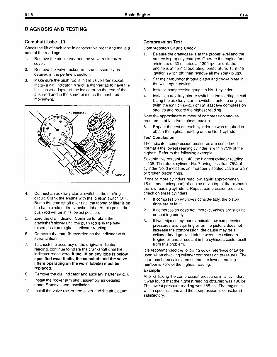
Camshaft Lobe Lift Compression Test
Check the lift of each lobe in consecutive order and make a
note of the readings.
1. Remove the air cleaner and the valve rocker arm
cover.
2. Remove the valve rocker arm shaft assembly as
detailed in the pertinent section.
3. Make sure the push rod is in the valve lifter socket.
Install a dial indicator in such a manner as to have the
ball socket adapter of the indicator on the end of the
push rod and in the same plane as the push rod
movement.
Compression Gauge Check
1. Be sure the crankcase is at the proper level and the
battery is properly charged. Operate the engine for a
minimum of 30 minutes at 1200 rpm or until the
engine is at normal operating temperature. Turn the
ignition switch off; then remove all the spark plugs.
2. Set the carburetor throttle plates and choke plate in
the wide open position.
3. Install a compression gauge in No. 1 cylinder.
4. Install an auxiliary starter switch in the starting circuit.
Using the auxiliary starter switch, crank the engine
(with the ignition switch off) at least five compression
strokes and record the highest reading.
Note the approximate number of compression strokes
required to obtain the highest reading.
5. Repeat the test on each cylinder as was required to
obtain the highest reading on the No. 1 cylinder.
Test Conclusion
1-A
4. Connect an auxiliary starter switch in the starting
circuit. Crank the engine with the ignition switch OFF.
Bump the crankshaft over until the tappet or lifter is on
the base circle of the camshaft lobe. At this point, the
push rod will be in its lowest position.
5. Zero the dial indicator. Continue to rotate the
crankshaft slowly until the push rod is in the fully
raised position (highest indicator reading).
6. Compare the total lift recorded on the indicator with
specifications.
7. To check the accuracy of the original indicator
reading, continue to rotate the crankshaft until the
indicator reads zero. If the lift on any lobe is below
specified wear limits, the camshaft and the valve
lifters operating on the worn lobe(s) must be
replaced.
8. Remove the dial indicator and auxiliary starter switch.
9. Install the rocker arm shaft assembly as detailed
under Removal and Installation.
IO. Install the valve rocker arm cover and the air cleaner.
The indicated compression pressures are considered
normal if the lowest reading cylinder is within 75% of the
highest. Refer to the following example.
Seventy-five percent of 140, the highest cylinder reading,
is 105. Therefore, cylinder No. 7 being less than 75% of
cylinder No. 3 indicates an improperly seated valve or worn
or broken piston rings.
If one or more cylinders read low, squirt approximately
15 ml (one tablespoon) of engine oil on top of the pistons in
the low reading cylinders. Repeat compression pressure
check on these cylinders.
1. If compression improves considerably, the piston
rings are at fault.
2. If compression does not improve, valves are sticking
or seat ing poorly.
3. If two adjacent cylinders indicate low compression
pressures and squirting oil on the pistons does not
increase the compression, the cause may be a
cylinder head gasket leak between the cylinders.
Engine oil and/or coolant in the cylinders could result
from this problem.
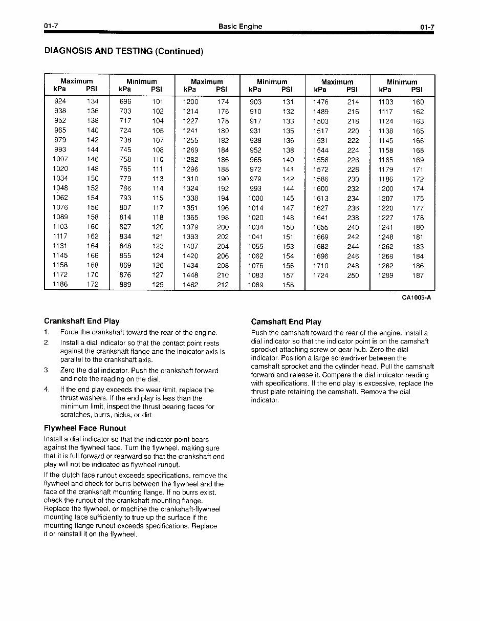
It is recommended the following quick reference chart be
used when checking cylinder compression pressures. The
chart has been calculated so that the lowest reading
number is 75% of the highest reading.
Example
After checking the compression pressures in all cylinders,
it was found that the highest reading obtained was 196 psi.
The lowest pressure reading was 155 psi. The engine is
within specifications and the compression is considered
satisfactory.
01-7 Basic Engine 01-7
DIAGNOSIS AND TESTING (Continued)
Maximum Minimum Maximum Minimum
kPa PSI kPa PSI kPa PSI kPa PSI
924 134 696 101 1200 174 903 131
938 136 703 102 1214 176 910 132
952 138 717 104 1227 178 917 133
965 140 724 105 1241 180 931 135
979 142 738 107 1255 182 938 136
993 144 745 108 1269 184 952 138
1007 146 758 110 1282 186 965 140
1020 148 765 111 1296 188 972 141
1034 150 779 113 1310 190 979 142
1048 152 786 114 1324 192 993 144
1662 154 793 115 1338 194 1000 145
1076 156 807 117 1351 196 1014 147
1089 158 814 118 1365 198 1020 148
1103 160 827 120 1379 200 1034 150
1117 162 834 121 1393 202 1041 151
1131 164 848 123 1407 204 1055 153
1145 166 855 124 1420 206 1062 154
1158 168 869 126 1434 208 1076 156
1172 170 -876 127 1448 210 1083 157
1186 172 889 129 1462 212 1089 158
Maximum Minimum
kPa PSI kPa PSI
1476 214 1103 160
1489 216 1117 162
1503 218 1124 163
1517 220 1138 165
1531 222 1145 166
1544 224 1158 168
1558 226 1165 169
1572 228 1179 171’
1586 230 1186 172
1600 232 1200 174
1613 234 1207 175
1627 236 1220 177
1641 238 1227 178
1655 240 1241 180
1669 242 1248 181
1682 244 1262 183
1696 246 1269 184
1710 248 1282 186
1724 250 1289 187
Crankshaft End Play
1. Force the crankshaft toward the rear of the engine.
2. Install a dial indicator so that the contact point rests
against the crankshaft flange and the indicator axis is
parallel to the crankshaft axis.
3. Zero the dial indicator. Push the crankshaft forward
and note the reading on the dial.
4. If the end play exceeds the wear limit, replace the
thrust washers. If the end play is less than the
minimum limit, inspect the thrust bearing faces for
scratches, burrs, nicks, or dirt.
Camshaft End Play
Push the camshaft toward the rear of the engine. Install a
dial indicator so that the indicator point is on the camshaft
sprocket attaching screw or gear hub. Zero the dial
indicator. Position a large screwdriver between the
camshaft sprocket and the cylinder head. Pull the camshaft
forward and release it. Compare the dial indicator reading
with specifications. If the end play is excessive, replace the
thrust plate retaining the camshaft. Remove the dial
indicator.
Flywheel Face Runout
Install a dial indicator so that the indicator point bears
against the flywheel face. Turn the flywheel, making sure
that it is full forward or rearward so that the crankshaft end
play will not be indicated as flywheel runout.
If the clutch face runout exceeds specifications, remove the
flywheel and check for burrs between the flywheel and the
face of the crankshaft mounting flange. If no burrs exist,
check the runout of the crankshaft mounting flange.
Replace the flywheel, or machine the crankshaft-flywheel
mounting face sufficiently to true up the surface if the
mounting flange runout exceeds specifications. Replace
it or reinstall it on the flywheel.
You're Reading a Preview
What's Included?
Fast Download Speeds
Online & Offline Access
Access PDF Contents & Bookmarks
Full Search Facility
Print one or all pages of your manual
$31.99
Viewed 55 Times Today


Secure transaction
What's Included?
Fast Download Speeds
Online & Offline Access
Access PDF Contents & Bookmarks
Full Search Facility
Print one or all pages of your manual
$31.99
The Ford VSG-411 and 413 service manual is an essential resource for anyone involved in the maintenance and repair of these engines. Whether you are a professional mechanic or a DIY enthusiast, this manual provides detailed technical information to help you understand, troubleshoot, and repair the engine effectively.
With comprehensive diagrams, step-by-step procedures, and specifications, this manual covers a wide range of topics including engine assembly, disassembly, maintenance, and troubleshooting. It is an invaluable tool for ensuring the proper functioning and longevity of the Ford VSG-411 and 413 engines.


