

Ford 2.5L (153 CID) LRG-425 Industrial Engine Service & Repair Manual
What's Included?
Fast Download Speeds
Online & Offline Access
Access PDF Contents & Bookmarks
Full Search Facility
Print one or all pages of your manual
LRG-425
2.5 LITER
(153 CID)
INDUSTRIAL ENGINE SERVICE MANUAL

IMPORTANT SAFETY NOTICE
Appropriate service methods and proper repair procedures are essential for the safe, reliable operation of all
industrial engines as well as the personal safety of the individual doing the work. This Service Manual provides
general directions for accomplishing service and repair work with tested, effective techniques. Following them will
help assure reliability.
There are numerous variations in procedures, techniques, tools and parts for servicing equipment, as well as in the
skill of the individual doing the work. This Manual cannot possibly anticipate all such variations and provide advice
or cautions as to each. Accordingly, anyone who departs from the instructions provided in this Manual must first
establish that he compromises neither his personal safety nor the equipment integrity by his choice of methods, tools
or parts.
NOTES, CAUTIONS, AND WARNINGS
As you read through the procedures, you will come across NOTES, CAUTIONS, and WARNINGS. Each one is
there for a specific purpose. NOTES give you added information that will help you to complete a particular
procedure. CAUTIONS are given to prevent you from making an error that could damage the equipment.
WARNINGS remind you to be especially careful in those areas where carelessness can cause personal injury. The
following list contains some general WARNINGS that you should follow when you work on the equipment.
• Always wear safety glasses for eye protection.
• Use safety stands whenever a procedure requires you to be under the equipment.
• Be sure that the ignition switch is always in the OFF position, unless otherwise required by the
procedure.
• Set the parking brake (if equipped) when working on the equipment. If you have an automatic
transmission, set it in PARK REVERSE (engine off) or NEUTRAL (engine on) unless instructed
otherwise for a specific operation. Place wood blocks (4” x 4” or larger) to the front and rear
surfaces of the tires to provide further restraint from inadvertent equipment movement.
• Operate the engine only in a well ventilated area to avoid the danger of carbon monoxide.
• Keep yourself and your clothing away from moving parts when the engine is running, especially the
fan and belts.
• To prevent serious burns, avoid contact with hot metal parts such as the radiator, exhaust manifold,
tail pipe, catalytic converter and muffler.
• Do not smoke while working on the equipment.
• To avoid injury, always remove rings, watches, loose hanging jewelry, and loose clothing before
beginning to work on the equipment. Tie long hair securely behind the head.
• Keep hands and other objects clear of the radiator fan blades. Electric cooling fans can start to
operate at any time by an increase in underhood temperatures, even through the ignition is in the
OFF position. Therefore, care should be taken to ensure that the electric cooling fan is completely
disconnected when working under the hood.

Introduction
In general, this manual covers the servicing of the engine and
associated standard equipment. In many cases, engines are
supplied with accessories and equipment that are unique to the
application. If service information is ever required on such unique
accessories or equipment it is suggested that Ford Power Products
be contacted. The proper information will either be forwarded or the
Service Technician will be advised where it can be obtained.
The information in this manual is grouped in sections according to
the type of work being performed. The various sections are indicated
in the index. In addition, each section is subdivided to include
topics such as diagnosis and testing, cleaning and inspection,
overhaul, removal and installation procedures, disassembly and
assembly procedures, and service specifications.
Special service tools called for by the procedures can be obtained by
calling:
1-800-ROTUNDA (1-800-768-8632).
The descriptions and specifications contained in this manual were in
effect at the time the book was released for printing. Ford Power
Products reserves the right to discontinue models at any time, or
change specifications or design, without notice and without incurring
obligation.
NOTE: The recommendations and suggestions contained in this
publication are made to assist the distributor in improving his
distributorship parts and/or service department operations. These
recommendations and suggestions do not supersede or override the
provisions of the Warranty and Policy Manual and in any cases
where there may be a conflict, the provisions of the Warranty and
Policy Manual shall govern.
Reroduction in any manner, in whole or in part, is prohibited without
The express permission in writing from:
Ford Power Products, Marketing Department.

TABLE OF CONTENTS
SECTION TITLE PAGE
ENGINE SERVICE - GENERAL ................................................................................................01
ENGINE SERVICE – 2.5L .........................................................................................................02
IGNITION SYSTEM ...................................................................................................................03
FUEL PUMP ..............................................................................................................................04
CARBURETOR ..........................................................................................................................05
STARTER MOTOR ....................................................................................................................06
GOVERNOR ..............................................................................................................................07
COOLING SYSTEM...................................................................................................................08
GENERATOR ............................................................................................................................09

01-1 Engine Service - General 01-1
SECTION TITLE PAGE
ENGINE SERVICE - General ................................................................................................................................ 01-01
ENGINE SERVICE - 2.5L ...................................................................................................................................... 02-01
IGNITION SYSTEM ............................................................................................................................................... 03-01
FUEL PUMP ......................................................................................................................................................... 04-01
CARBURETOR...................................................................................................................................................... 05-01
STARTER MOTOR................................................................................................................................................ 06-01
GOVERNOR .......................................................................................................................................................... 07-01
COOLING SYSTEM .............................................................................................................................................. 08-01
GENERATOR ........................................................................................................................................................ 09-01
SECTION 01 - Engine Service - General
SUBJECT PAGE
DESCRIPTION ............................................................................................................................................................. 2
Introduction .............................................................................................................................................................. 2
Engine Identification Nameplate .............................................................................................................................. 2
DIAGNOSIS .................................................................................................................................................................. 3
Inspection................................................................................................................................................................. 3
Symptom Chart ........................................................................................................................................................ 3
PCV System Malfunction ......................................................................................................................................... 5
Engine Oil Leak Check ............................................................................................................................................ 5
Compression Test .................................................................................................................................................... 7
Cylinder Leakage Test ............................................................................................................................................. 8
Oil Leak and Valve Guide Seal Test ........................................................................................................................ 8
Intake Manifold Vacuum Test .................................................................................................................................. 8
Oil Consumption Test ............................................................................................................................................ 10
Oil Pressure Test ................................................................................................................................................... 11
SERVICE PROCEDURES.......................................................................................................................................... 12
Camshaft Service................................................................................................................................................... 12
Connecting Rod Service ........................................................................................................................................ 14
Crankshaft Bearing Service ................................................................................................................................... 15
Crankshaft Service................................................................................................................................................. 18
Cylinder Block Service ........................................................................................................................................... 20
Cylinder Head Service ........................................................................................................................................... 23
Engine Block Plug Service..................................................................................................................................... 31
Exhaust Manifold Service ...................................................................................................................................... 32
Hydraulic Valve Tappet/Adjuster Service............................................................................................................... 32
Intake Manifold Service.......................................................................................................................................... 34
Oil Pan Service ...................................................................................................................................................... 34
Piston Service ........................................................................................................................................................ 34
SPECIAL TOOLS ....................................................................................................................................................... 38
01-2 Engine Service - General 01-2
DESCRIPTION
DESCRIPTION
Introduction
This section covers various engine tests, adjustments,
service procedures and cleaning/inspection
procedures. Engine assembly and service
specifications appear at the end of Section 02.
For engine disassembly, assembly, installation,
adjustment procedures and specifications, refer to
Section 02.
Most Ford Power Product engines incorporate a
closed-type crankcase ventilation system. Other than
the crankcase ventilation system there are no exhaust
emission controls or engine/emission control systems
used with industrial versions of these engines.
To maintain the required performance level, the fuel
system, ignition system and engine must be kept in
good operating condition and meet recommended
adjustment specifications.
Before replacing damaged or worn engine
components such as the crankshaft, cylinder head,
valve guide, valves, camshaft or cylinder block, make
sure part(s) is not serviceable.
WARNING: TO AVOID THE POSSIBILITY OF
PERSONAL INJURY OR DAMAGE, DO NOT
OPERATE THE ENGINE UNTIL THE FAN BLADE
HAS FIRST BEEN EXAMINED FOR POSSIBLE
CRACKS OR SEPARATION.
CAUTION: Use of abrasive grinding discs to
remove gasket material from the engine sealing
surfaces during repair procedures can contribute
to engine damage and wear. Airborne debris and
abrasive grit from the grinding disc may enter the
engine through exposed cavities causing
premature wear and eventual engine damage.
Ford Power Products does not recommend using
abrasive grinding discs to remove engine gasket
material. Use manual gasket scrapers for removing
gasket material from the engine sealing surfaces.
Take added care to prevent scratching or gouging
aluminum sealing surfaces.
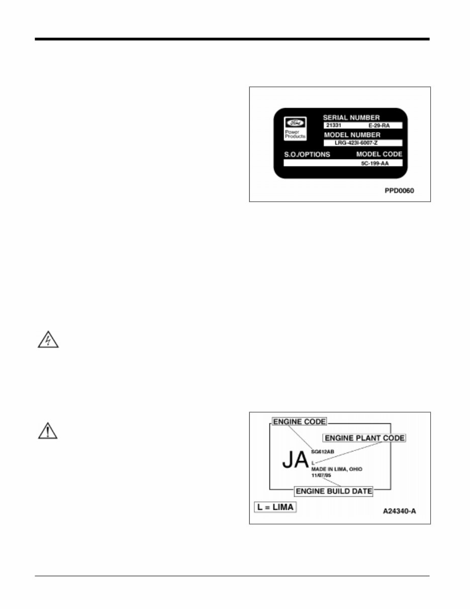
Engine Identification Nameplate
For quick engine identification, refer to the Engine
Identification Nameplate. The nameplate lists engine
information required for proper servicing of the
engine. The Engine Identification Nameplate and
identification label provide information pertaining to
engine displacement, serial number, model number,
S.O./Options, and model code.
An engine code decal is attached to the engine front
cover. The symbol code on the decal identifies each
engine for determining parts usage.

01-3 Engine Service - General 01-3
DIAGNOSIS
DIAGNOSIS
Inspection
Inspect to determine if any of the following mechanical concerns apply:
• Engine oil leaks.
• Damaged and/or severely worn parts.
• Loose mounting bolts, studs and nuts.
CONDITION POSSIBLE SOURCE ACTION
DIFFICULT
STARTING
• Burnt valve.
• Worn piston.
• Worn piston ring(s).
• Worn cylinder.
• Damaged cylinder head gasket.
• Malfunctioning or damaged fuel system.
• Malfunctioning or damaged ignition system.
• Replace valve.
• Replace piston.
• Replace piston ring(s).
• Service or replace cylinder block.
• Replace cylinder head gasket.
• Refer to section on fuel system.
• Refer to section on ignition system.
POOR IDLING
• Damaged hydraulic valve tappet.
• Damaged hydraulic valve tappet guide.
• Improper valve to valve seat contact.
• Damaged cylinder head gasket.
• Malfunctioning or damaged fuel system.
• Malfunctioning or damaged ignition system.
• Replace hydraulic valve tappet.
• Replace hydraulic valve tappet
guide.
• Replace valve and/or valve seat.
• Replace cylinder head gasket.
• Refer to section on Fuel system.
• Refer to section on ignition system.
ABNORMAL
COMBUSTION
• Damaged hydraulic valve tappet.
• Damaged hydraulic valve tappet bore.
• Burnt or sticking valve.
• Weak or broken valve spring.
• Carbon accumulation in combustion chamber.
• Malfunctioning or damaged fuel system.
• Malfunctioning or damaged ignition system.
• Replace hydraulic valve tappet.
• Replace cylinder block.
• Service or replace valve.
• Replace valve spring.
• Eliminate carbon buildup.
• Refer to section on fuel system.
• Refer to section on ignition system.
EXCESSIVE OIL
CONSUMPTION
• Worn piston ring groove.
• Sticking piston ring(s).
• Worn piston or cylinder.
• Worn valve stem seal.
• Worn valve stem or valve guides.
• Leaking oil.
• Worn piston rings.
• Plugged pcv system.
• Replace piston.
• Service or replace piston ring (s).
• Service or replace piston or cylinder
block.
• Replace valve stem seal.
• Replace valve stem and guide.
• Service oil leak.
• Replace piston rings.
• Service PCV system.

01-4 Engine Service - General 01-4
DIAGNOSIS
CONDITION POSSIBLE SOURCE ACTION
ENGINE NOISE
• Excessive main bearing oil clearance.
• Seized or heat damaged crankshaft main
bearing.
• Excessive crankshaft end play.
• Excessive connecting rod bearing oil
clearance.
• Heat damaged connecting rod bearing.
• Damaged connecting rod bushing.
• Worn cylinder.
• Worn piston or piston pin.
• Damaged piston ring(s).
• Bent connecting rod.
• Malfunctioning hydraulic valve tappet.
• Excessive hydraulic valve tappet clearance.
• Broken valve spring.
• Excessive valve guide clearance.
• Malfunctioning or damaged cooling system.
• Malfunctioning or damaged fuel system.
• Leaking exhaust system.
• Improper drive belt tension.
• Malfunctioning generator bearing.
• Loose riming belt.
• Damaged timing belt tensioner.
• Malfunctioning water pump bearing.
• Adjust clearance or replace
crankshaft main bearing.
• Replace crankshaft main bearing.
• Adjust end play or replace
crankshaft.
• Adjust clearance or replace
connecting rod.
• Replace connecting rod bearing.
• Replace connecting rod bushing.
• Service or replace cylinder block.
• Replace piston or piston pin.
• Replace piston ring(s).
• Replace connecting rod.
• Replace hydraulic valve tappet.
• Adjust clearance or replace
hydraulic valve tappet.
• Replace valve spring.
• Service clearance or replace valve
guide/stem.
• Refer to section on cooling system.
• Refer to section on fuel system.
• Service exhaust leakage.
• Refer to section on accessory
drivebelts.
• Refer to section on charging system.
• Adjust or replace timing belt.
• Replace timing belt tensioner.
• Refer to section on cooling system.
INSUFFICIENT
POWER
• Malfunctioning hydraulic valve tappet.
• Damaged hydraulic valve tappet bore.
• Seized valve stem.
• Weak or broken valve spring.
• Damaged cylinder head gasket.
• Cracked or distorted cylinder head.
• Damaged, worn or sticking piston ring(s).
• Worn or damaged piston.
• Malfunctioning or damaged fuel system.
• Malfunctioning or damaged ignition system.
• Replace hydraulic valve tappet.
• Replace cylinder block.
• Service or replace valve, valve seat
and/or cylinder head.
• Replace valve spring.
• Replace cylinder head gasket.
• Replace cylinder head.
• Service or replace piston ring(s).
• Replace piston.
• Refer to section on fuel system.
• Refer to section on ignition system.
01-5 Engine Service - General 01-5
DIAGNOSIS
PCV System Malfunction
A malfunctioning Positive Crankcase Ventilation
System (closed type) may be indicated by loping or
rough engine idle. Do not attempt to compensate for
this idle condition by disconnecting the crankcase
ventilation system and making an air bypass or idle
speed adjustment. The removal of the crankcase
ventilation system from the engine will adversely
affect fuel economy and engine crankcase
ventilation with resultant shortening of engine
life.
Engine Oil Leak Check
When diagnosing engine oil leaks, it is important that
the source and location of the leak be positively
identified prior to service.
NOTE: Due to their remote location, rear engine
oil leaks may be very difficult to pinpoint. This
area is also very difficult to clean. Make sure to
eliminate all other possibilities before removing
the engine to repair a suspected leak in this area.
There are two methods of diagnosing engine oil leaks.
The following procedure has been found to be very
effective and requires only a minimum of equipment.
Prior to using this procedure, it is important to clean
the cylinder block, cylinder heads, valve covers, oil
pan and flywheel housing areas with a suitable
solvent to remove all traces of oil.
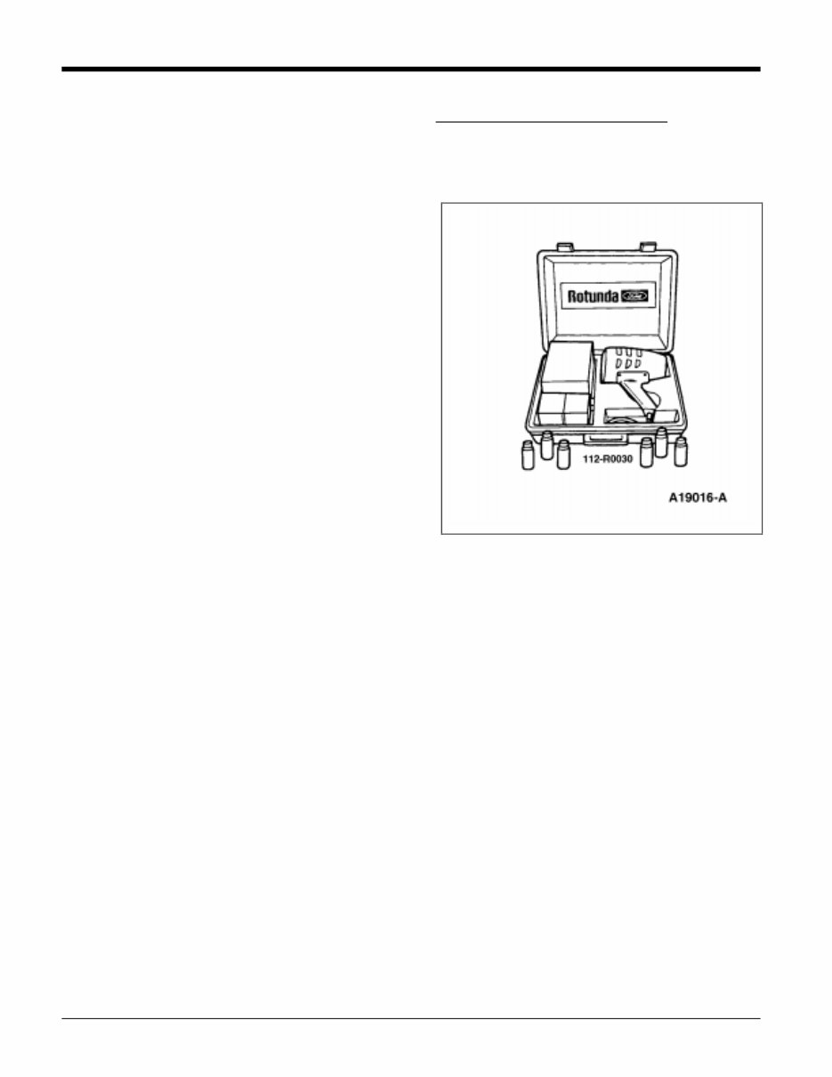
Fluorescent Oil Additive Method
To perform oil leak diagnosis using Rotunda Oil Leak
Detector Kit 112-R0030, or equivalent, perform the
following procedure.
1. Clean engine with a suitable solvent to remove all
traces of oil.
2. Drain engine oil from crankcase and refill with
recommended oil, premixed with Rotunda
Fluorescent Oil Additive 112-R0015, or
equivalent. Use 29.6ml (1 fluid once) of
fluorescent additive. If oil is not premixed,
fluorescent additive must be added to crankcase
first.
3. Run engine for 15 minutes. Stop engine and
inspect all seal and gasket areas for leaks using
Rotunda Oil Leak Detector Y112-R0021 (part of
112-R0030 kit) Lamp or equivalent. A clear bright
yellow or orange area will identify leak. For
extremely small leaks, several hours may be
required for the leak to appear.
4. If necessary, pressurize main oil gallery system to
locate leaks due to improperly sealed, loose or
cocked plugs. If flywheel bolts leak oil, look for
sealer on threads.
5. Service all leaks as required.

01-6 Engine Service - General 01-6
DIAGNOSIS
Pressure Method
As an alternative testing procedure, the crankcase
can be pressurized, not to exceed 27 kPa (4 psi), to
locate oil leaks. The following materials are required
to fabricate the tool to be used:
• Air supply and air hose.
• Air pressure gauge that registers pressure in
increments of one psi.
• Air line shutoff valve.
• Appropriate fittings to attach the above parts to oil
fill, PCV grommet holes and PCV fresh air hose
tube.
• Appropriate plugs to seal any openings leading to
crankcase.
• A solution of liquid detergent and water to be
applied with a suitable type applicator such as a
squirt bottle or brush.
Fabricate the air supply hose to include the air line
shutoff valve and the appropriate adapter to permit
the air to enter the engine through the rocker arm
cover tube. Fabricate the air pressure gauge to a
suitable adapter for installation on the engine at the oil
fill opening.
CAUTION: Use extreme caution when
pressurizing crankcase. Applying air pressure
above specified pressure risks damage to seals,
gaskets and core plugs. Under no circumstances
should pressure be allowed to exceed 27 kPa (4
psi).
1. Open air supply valve until pressure gauge
maintains 20 kPa (3 psi).
2. Inspect sealed and/or gasketed areas for leaks
by applying a solution of liquid detergent and
water over areas for formation of bubbles, which
indicates leakage.
3. Examine the following areas for oil leakage:
• Rocker cover sealant or gaskets
• Intake manifold gaskets/end seals
• Cylinder head gaskets
• Oil bypass filter
• Oil level indicator (dipstick) tube connection
• Oil pressure sensor
• Cup plugs and/or pipe plugs at end of oil
passages
• Oil pan gasket
• Oil pan front and rear end seals
• Oil pan front and rear end seals
• Crankshaft front seal
• Crankshaft rear oil seal
• Oil pump
• Crankshaft rear oil seal
Air leakage in area around a crankshaft rear oil seal
does not necessarily indicate a rear seal leak.
However, if no other cause can be found for oil
leakage, it can be assumed that rear seal is the cause
of the oil leakage:
• Rear main bearing cap parting line.
• Rear main bearing cap and seals.
• Flywheel mounting bolt holes.
• Rear cup plugs and/or pipe plugs at the end of oil
passages.
Oil leaks at crimped seams in sheet metal parts and
cracks in cast or stamped parts can be detected when
pressurizing the crankcase.
Light foaming equally around rocker arm cover bolts
and crankshaft seals is not detrimental and no
corrections are required in such cases.
You're Reading a Preview
What's Included?
Fast Download Speeds
Online & Offline Access
Access PDF Contents & Bookmarks
Full Search Facility
Print one or all pages of your manual
$35.99
Viewed 57 Times Today


Secure transaction
What's Included?
Fast Download Speeds
Online & Offline Access
Access PDF Contents & Bookmarks
Full Search Facility
Print one or all pages of your manual
$35.99
This workshop service repair manual is for the Ford 2.5L (153 CID) LRG-425 Industrial Engine Service & Repair Manual and includes an operator's manual. The manual covers the 2.5L I-4 cylinder, 4-stroke, spark ignition engine and provides the following detailed technical information:
- Engine service procedures and torque specifications
- Ignition system and fuel pump system details
- Engine diagnosis and troubleshooting guidelines
- Step-by-step instructions for engine removal and installation
- Camshaft, connecting rod, and crankshaft service procedures
- Cylinder block and cylinder head servicing information
- Engine block plug, exhaust manifold, and hydraulic valve tappet/adjuster service details
- Intake manifold, oil pan, piston, and carburetor system maintenance
- Information on starter motor, governor system, cooling system, and generator system
- Lists of special tools and wiring diagrams
This comprehensive manual is available in .PDF format and features detailed exploded views, clear illustrations, and diagrams. It is designed to assist both professional mechanics and DIY enthusiasts with repairs, maintenance, and servicing of the Ford 2.5L (153 CID) LRG-425 Industrial Engine.


