

EMS2 Deutz Fault Codes
What's Included?
Fast Download Speeds
Online & Offline Access
Access PDF Contents & Bookmarks
Full Search Facility
Print one or all pages of your manual

System description
Electronic monitoring system EMS 2


© 0702 Page 55
EMS 2
1 Foreword
This system description provides an overview of the design and the operation of the electronic monitoring
system (EMS 2).
In addition, the functions which the EMS 2 contains, and the manner in which problems in the engine and in
the EMS 2 can be detected, are explained.

Page 56 © 0702
EMS 2
© 0702 Page 57
EMS 2
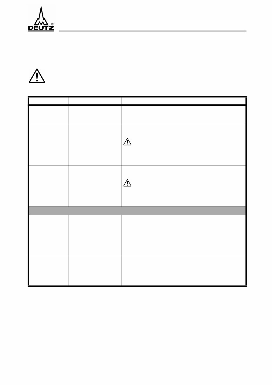
Important notes
2 Important notes
In the event of critical conditions, the EMS 2 may independently shut the engine off, either
with or without prior warning depending on the configuration, or may merely provide a
warning. The user must be informed of this and must be familiarised with limp-home mode.
! The following states can be recognised with the diagnostic lamp
! The illumination of the maintenance/service lamp demands that the engine be maintained by the
DEUTZ Service department.
Display State Indicates
Diagnostic lamp
illuminates for 2 s
from ignition on.
Lamp test System is ready for operation.
Diagnostic lamp
continuously
illuminated.
Warning
regarding exceeded limit
values and system faults.
A reduction in power is only possible in combination with
an engine governor, e.g. EMR and MVS.
The reduction in power can be temporarily bridged with
the limp-home mode button. (Depression of the
button is confirmed with slow flashing, see *).
After the engine has been shut-off, fault code enquiry is
possible (see **).
Diagnostic lamp
flashes rapidly
(approx. 1 Hz).
Emergency engine
shut-off if shut-off limits
are exceeded or not
achieved.
Attention: In a few seconds, the engine will be
automatically shut-off for the purpose of protection.
The reduction in power can be temporarily bridged with
the limp-home mode button. (Depression of the
button is confirmed with slow flashing, see *).
After the engine has been shut-off, fault code enquiry is
possible (see **).
* Diagnostic lamp
flashes slowly
(approx. 0.5 Hz).
The limp-home mode
button has been
actuated in order to
bridge the reduction in
power or engine shut-off.
Bridging is stored in the
control unit.
Attention: Following actuation of the limp-home mode
button, the engine continues to run without protection for
a short time, and may become damaged! For this reason,
only actuate the button in the event of an emergency
(e.g. if life is otherwise placed at risk)!
** Fault code
enquiry
The diagnostic lamp ser-
ves to display a fault
code (a sequence of
short and long flashing
impulses).
In the event of engine standstill, an enquiry regarding the
fault code may be made with the limp-home mode button/
diagnostic button, see Chapter 8.4.

Page 58 © 0702
EMS 2
Important notes
© 0702 Page 59
EMS 2
System description
3 System description
3.1 Use of the EMS 2
The EMS 2 is a monitoring system for the 1013, 1015 engine model series. It can be used on its own and
also in combination with the MVS (solenoid valve system) or the EMR (electronic engine governor).
The EMS 2 provides functions for engine protection, for indicating maintenance requirements and for
diagnostic purposes. With the aid of the data recorder function, an overview of the manner of operation,
capacity utilisation and possible causes of engine failure may be obtained. In addition, data exchange with
other electronic control units (e.g. EMR, MVS) is possible via the CAN interface.
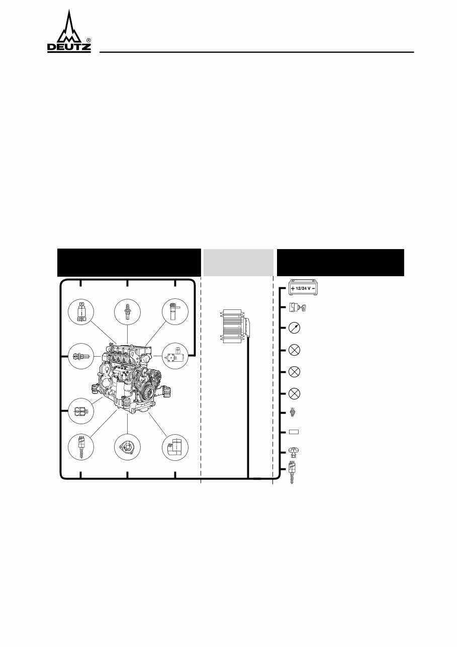
3.2 System overview
3.2.1 EMS 2 alone
EMS
Control unit
Vehicle-side/
System-side facility
Engine-side facility
Energy supply
Glow-start switch
Multi-functional display
Configurable outputs
(e.g. indicator lamps)
Maintenance/service
Diagnostic lamp
Flame system
solenoid valve
Flame system
temperature sensor
Engine speed
Oil level switch Alternator Starter
Coolant
temperature sensor
Engine shut-off
lifting magnet
Oil pressure
sensor
Diagnostic button/
limp-home button
Diagnostic interfaces
• S, L line (ISO 9141)
• CAN bus (SAE J1939)
• SAE J1708 / J1587
Air filter differential
pressure sensor
Coolant level switch
© 0702
Page 60 © 0702
EMS 2
System description
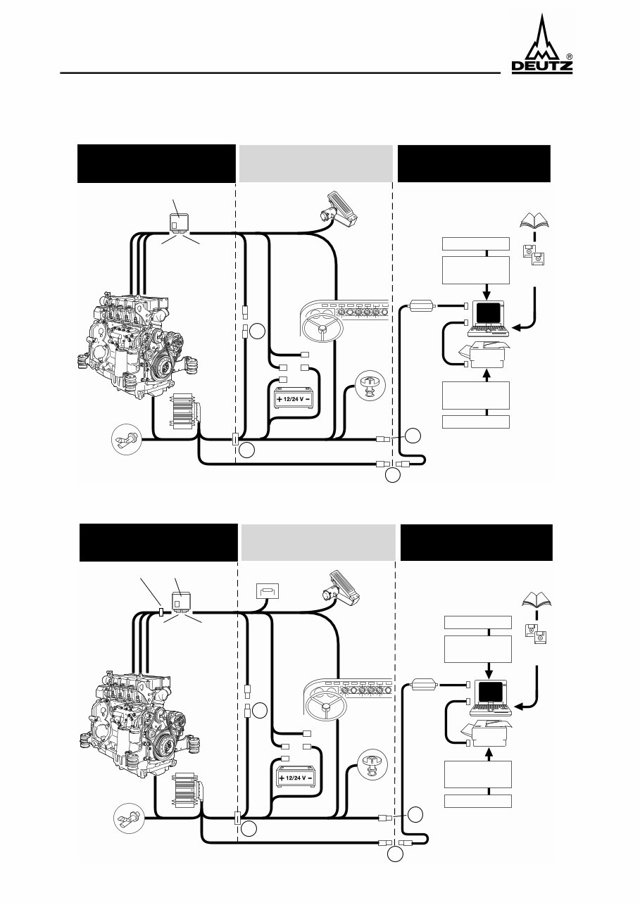
3.2.2 EMS 2 in combination with MVS
3.2.3 EMS 2 in combination with EMR
Vehicle-side installation Service
Interface
Software
disc
User level
depending on
authorization
Power supply
or
battery
Accelerator pedal
Interface
SAE J1708/
J1587
Diagnostic plug
Part No.: 0419 9615
Central
plug
Diagnostic lamp (MVS)
Diagnostic button (MVS)
Indicator lamp (EMS)
Maintenance/service (EMS)
Diagnostic lamp (EMS)
Diagnostic button/limp-home button (EMS)
Operating manual
110 / 220 V~
110 / 220 V~
Power supply
or
battery
Printer
Engine
plug
Vehicle
plug
MVS
Engine
wiring
harness
DEUTZ scope of delivery
EMS 2
X23
Coolant
level sensor
Air filter
differential
pressure switch
CAN
X22
X25
X26
© 0702
Vehicle-side installation Service
Interface
Software
disc
User level
depending on
authorization
Power supply
or
battery
Terminating
resistor (CAN)
Accelerator
pedal
Interface
SAE J1708/
J1587
Diagnostic plug
Part No.: 0419 9615
Central
plug
X23
Coolant
level sensor
Air filter
differential
pressure switch
CAN
Operating manual
110 / 220 V~
110 / 220 V~
Power supply
or
battery
Printer
Engine
plug
Vehicle
plug
EMR
Engine
wiring
harness
Transfer plug
DEUTZ scope of delivery
EMS 2
Fault lamp (EMR)
Indicator lamp (EMS)
Maintenance/service (EMS)
Diagnostic lamp (EMS)
Diagnostic button/limp-home button (EMS)
X22
X25
X26
© 0702

© 0702 Page 61
EMS 2
System functions
4 System functions
1
4.1 Introduction
The EMS 2 serves to electronically monitor the engine. Its functions include:
Engine protection functions
● Warning the operator if limit values are exceeded or not achieved.
● Reduction in engine power.
● Emergency engine shut-off if operating data exceed or do not achieve the shut-off limits.
Indication of maintenance requirements
in order to remind the operator and to reduce the consumption of operating media. The maintenance
intervals can be obtained from the DEUTZ engine operating instructions, Chapter 5.1.
● in the event of excessive air filter differential pressure.
● if the number of operating hours leads to the achievement of the next maintenance requirements.
● if the load population reaches a maintenance limit.
● if calculation of the engine operating statuses (temperatures, speed, etc.) results in the oil change limit's
being exceeded.
Data exchange
with other systems via the CAN interface, e.g. with the solenoid valve system (MVS):
● Transmission of the output reduction signal if limit values are exceeded.
● Engine shut-off via the CAN interface sets, e.g. the fuel injection quantity to zero.
● The integration of measurement data and fault messages via the CAN interface extends the input signals
of the EMS 2 for executing engine protection functions and system diagnosis (see above).
● Transfer of the EMS 2 measurement data to other systems.
Diagnosis of the entire system
● System self-diagnosis, i.e. of the control unit, the sensors and the actuators.
● Display of engine operating data and self-diagnosis data on a PC (ISO9141 / RS232).
● Forwarding of the engine operating data to the SAE-J1708/1587 interface for diagnostic and display
systems.
● Actuation of a telltale and output of a flashing code for fault identification.
Data recorder
Determination of the manner of operation, capacity utilisation and causes of engine failure.
● Recording the most important measurement variable signals.
● Determination of the load population.
● Storage of exceeded maintenance intervals.
● Documentation of hours of engine operation.
Engine operation display
● Output of a signal (telltale or relay) as soon as the speed exceeds 400 rpm.
1)
Not all functions are available in all applications.

Page 62 © 0702
EMS 2
System functions
4.2 Engine protection functions
4.2.1 General
The following table contains an overview of the measurement variables which can be monitored, together
with the relevant, possible engine protection functions.
● If the measurement variable lies within the warning range, the diagnostic lamp is continuously illumi-
nated. As a result of a command via the CAN interface to the EMR or MVS, the power is reduced. If the
measurement variable exceeds/does not achieve the recovery threshold, the lamp is extinguished again.
● A reduction in power is only possible in combination with EMR and MVS.
● If the measurement lies within the shut-off range, emergency engine shut-off is carried out following
the expiry of a waiting period. The diagnostic lamp flashes rapidly (frequency approx. 1 Hz). Shut-off is
effected either
- via a shut-off solenoid or
- via the CAN interface on other electronic control units (EMR, MVS)
● Limit values which are exceeded or not achieved are documented in the fault memory .
● The fault message is output if the diagnostic button is actuated during engine standstill
- as a flashing code via the diagnostic lamp.
- with a notebook connected via the ISO9141 interface with the SERDIA diagnostic programme.
- via the ISO J1708/1587 interface according to standard.
● Starting prevention can be recognised via the rapid flashing of the diagnostic lamp (1Hz) in the event of
engine standstill. If the EMS 2 has shut the engine off on the basis of the engine monitoring functions,
restarting is prevented. The same applies if monitoring is carried out during standstill, and engine star-
ting is blocked due e.g. a low coolant level.
● The engine can be restarted by switching the ignition off/on (terminal 15).
● Outputs may also be used to initialise lamps or relays if limit values are exceeded or not achieved, see
Chapter entitled Outputs 5.2.
Monitorable measurement variable
Possible engine protection function
1
1
The configuration is programmed in the factory.
Warning Power reduction Emergency engine
shut-off
Speed x x
Oil temperature x x x
Coolant temperature x x x
Cylinder temperature 1 x x x
Cylinder temperature 2 x x x
Oil pressure x x x
Coolant leveld x x x
Oil level x x x
Reserve signal T1 x x x
You're Reading a Preview
What's Included?
Fast Download Speeds
Online & Offline Access
Access PDF Contents & Bookmarks
Full Search Facility
Print one or all pages of your manual
$26.99
$35.99
Viewed 35 Times Today


Secure transaction
What's Included?
Fast Download Speeds
Online & Offline Access
Access PDF Contents & Bookmarks
Full Search Facility
Print one or all pages of your manual
$26.99
$35.99
The EMS2 Deutz Fault Codes manual is an essential resource for mechanics and enthusiasts working on Deutz engines. With 54 pages of detailed information, it covers fault codes for various models including:
- Diesel Engine D/TD226B/3/4 Series
- Diesel Engine D1100C, TD2011L04
- Diesel Engine D2.9/3.7/4.1/5.1 Series
- Diesel Engine D2008, TD2008, BD2008 Series
- Diesel Engine D2009L03, TD2009L03/TBD2009L03 Series
- Diesel Engine D2012/T2012L, D2012/T2012C, D2012/T2012W Series
- Diesel Engine D2013L03T Series
- Engines Series BF3M, BF4M, BF6M, BF6ME, BF4M1011, BF4M1013, BF3M1011E
Whether you're a professional mechanic or a DIY enthusiast, this manual equips you with the necessary information to diagnose and address issues effectively, ultimately saving time and resources. The content is presented in a clear and understandable manner, making it an invaluable tool for anyone working with Deutz engines.
Acquire this comprehensive EMS2 Deutz Fault Codes manual to access practical and vital information for maintaining and repairing Deutz engines.


