DETROIT DIESEL
V-71 Service Manual
Sections 1-3
D __ e_T_R_o_•_T_~-!-~-0-~-~- . o-~---- ~
3400 Outer Drive. West I Detroit. Michigan 48239-4001
Telephone. 313-592-5000
Telex 4320091 I TWX: 810-221-1649
Fax· 313-592-7288
6SE193 69090 De t ro it Diesel Corporation Lltho In USA
FOREWORD
Thi manual contains in truction on the overhaul, maintenance
and oper at ion of the ba ic V- 71 Detroit D ie el En gi ne .
Fu ll bene fi t of the long life and dependability built into the e engine
can be realized thro ugh proper operation and maintenance. Of equal
importance i the u e of proper procedure during engine overhaul.
Pe onnel responsible for engine operation and maintenance hould
tudy the ection of the manual pertaining to their particular dutie .
imilarly, before beginning a repair or overhaul job , the erviceman
hould read the manual carefully to familiarize him elf with the part or
uba embli of the engine with which he ' ill be concerned.
The information, pecification and illu trarion in thi. publication
are ba ed on the information in effect at the time of approval for printing.
Thi publication i revi ed and reprinted periodically. It i recommended
that u er contact an authorized Detroit Di el Corporation ervi e
Outlet for information on the latest revi ion . he right i r erved to
make changes at any time without obligation.
TNEWCAMP MANUALS
CAUTION
To reduce the chance of per onal injury and/or property damage,
the following inst.ructions must be carefully observed .
Proper ervice and repair are important to the safety of the service
tecbnician and the safe, reliable operation of the engine. If part
replacement is necessary, the part mu t be replaced with one of the ame
part number or with an equivalent part. Do not u ea replacement part
of lesser quality.
The ervice procedures recommended by Detroit Diesel
Corporation and described in this service manual are effective method
of performing ervice and repair. Some of these procedures require the
use of tools specially designed for the purpose.
Accordingly, anyone who intends to use a replacement part,
service procedure or tool, which is not recommended by Detroit Diesel
Corporation, must first determine that neither his safety nor the safe
operation of the engine will be jeopardized by the replacement part,
service procedure or tool selected.
It i important to note that thi manual contain ariou
"Caution " and " otices' that mu t be carefully observed in order to
reduce the ri k of personal injury during ervice or repair or the
po sibility that improper service or repair may damage the engine or
render it unsafe. It is also important to understand that the e
'Caution " and "Notices" are not exhau tive, because it is impos ible
for Detroit Diesel Corporation to warn of all the possible hazardou
consequences that might result from failure to follow these instruction .
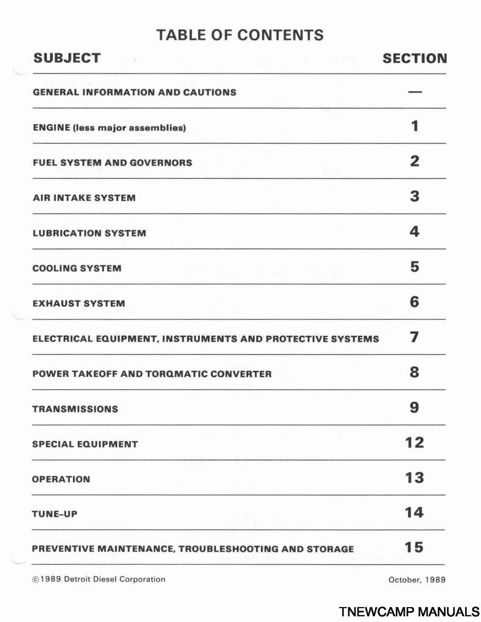
TABLE OF CONTENTS
SUBJECT SECTION
GENERAL INFORMATION AND CAUTIONS
ENGINE (less major assemblies) 1
FUEL SYSTEM AND GOVERNORS 2
AIR INTAKE SYSTEM 3
LUBRICATION SYSTEM 4
COOLING SYSTEM 5
EXHAUST SYSTEM 6
ELECTRICAL EQUIPMENT, INSTRUMENTS AND PROTECTIVE SYSTEMS 7
POWER TAKEOFF AND TORQMATIC CONVERTER 8
TRANSMISSIONS 9
SPECIAL EQUIPMENT 1 2
OPERATION 13
TUNE-UP 14
PREVENTIVE MAINTENANCE, TROUBLESHOOTING AND STORAGE 1 5
© 1989 Detroit Diesel Corporation October , 1989
TNEWCAMP MANUALS
General Information DETROIT DIESEL V-71
SCOPE AND USE OF THE MANUAL
Thi manual covers the basic V-71 Diesel Engine built by the Detroit Diesel Corporation. Complete instruction on
operation, adju tment (tune-up), preventive maintenance and lubrication, and repair (in.eluding complete overhaul) are
covered. The manual was written primarily for persons ervicing and overhauling the engine and, in addition, contain all of the
instruction es ential to the operators and u er . Basic maintenance and overhaul. procedures are common co all V -7 1 engines
and therefore, apply to all V- 71 model .
The manual is divided into numbered ections. The first ection covers the engine (le major as. emblie ). The following
ections cover a complete system such a the fuel system, lubrication sy tern or air system. Each ection is divided into
ubsections which contain complete maintenance and operating instruction for a pecitic . uba sembly on the engine. For
example, Section l, which cover the basic engine, contain ubsection I. I pertaining to the cylinder block, sub ection 1.2
covering the cylinder head, etc. The subject and ections are listed in the Table of Content on the preceding page. Page are
numbered consecutively, tarting with a new Page I at the beginning of each ubsection. The illustration are also numbered
consecutively, beginning with a new Fig. 1 at the start of each subsection.
Information regarding a general subject, such as the lubrication sy tern, can best be located by using the Table of
Contents. Opposite each ubject in the Table of Contents i a section number which regi ter \ itha tab printed on the fir t page
of each section throughout the manual. Information on a specific subassembly or acces ory can then be found by con ulting the
list of contents on the first page of the section. For example the cylinder liner is part of the basic engine. Therefore, it will be
found in Section 1. Looking down the list of contents on the first page of Section 1, the cylinder liner is found to bejn ubsection
1.6.3. An Alphabetical Index at the back of the manual has been provided a an additional aid for locating information.
SERVICE PARTS AVAILABILITY
Genuine Detroit Diesel service parts are available from authorized Detroit Die el distributor and ervice dealers
throughout the world. A complete list of all distributor and dealers i available in the Worldwide Di tributor and Dealer
Directory 6SE280. This publication can be ordered from any authorized di tributor.
CLEARANCES AND TORQUE SPECIFICATIONS
Clearance of new part and ~ ear limit on used part are listed in tabular form at the end of each e tion throughout the
manual. It hould be pecifically noted that the ' New Part ·" clearance apply only when all new part are used at the point
where lhe various specification apply. This al o applies to reference within the text of the manual. The column entitled
''Limits" Ii t the amount of wear or increa e in clearance which can be tolerated in u ed engine parts and till a ure
·atisfactory performance. It hould be emphasized that the figures given as "Limits' must be quaJjfied by the judgment of
personnel respon ible for in , tailing new part . These wear limits are in geoeraJ, Ii ted only for the parts more rrequently
replaced in engine overhaul work. For additional information, refer 10 the paragraph entitled Jn pection under General
Procedures in this ection.
Bolt, nut and stud torque pecification are al ·o Ii ted in tabular form at the end of each ection.
•PARTS REPLACEMENT
Before in talling a new or u ed part, check it thoroughly to make . ure il i the proper part for the job. The quality of the
replacement part must be equivalent to the quality of the original Detroit Die el component being replaced and mu t meet
DOC specification for new or reusable part .
Part mu t al o be clean and not phy icaJly damaged or defective. For example, bolt and bolt hole thread must not be
damaged or di . torted. Gasketing must have all holes completely punched through with no re idual gasket material left clinging
to the top or bottom. Flatne. and fit pecification in the service manual must be tri tly adhered to.
CAUTION: Failure to inspect parts thoroughly before installation, failure to install the proper
parts, or failure to install parts properly can result in component or engine malfunction and/or
damage and may also result in personal injury.
Page 4 October, 1989 © Detroit Diesel Corporation
--
DETROIT DIESEL V-71 General Information
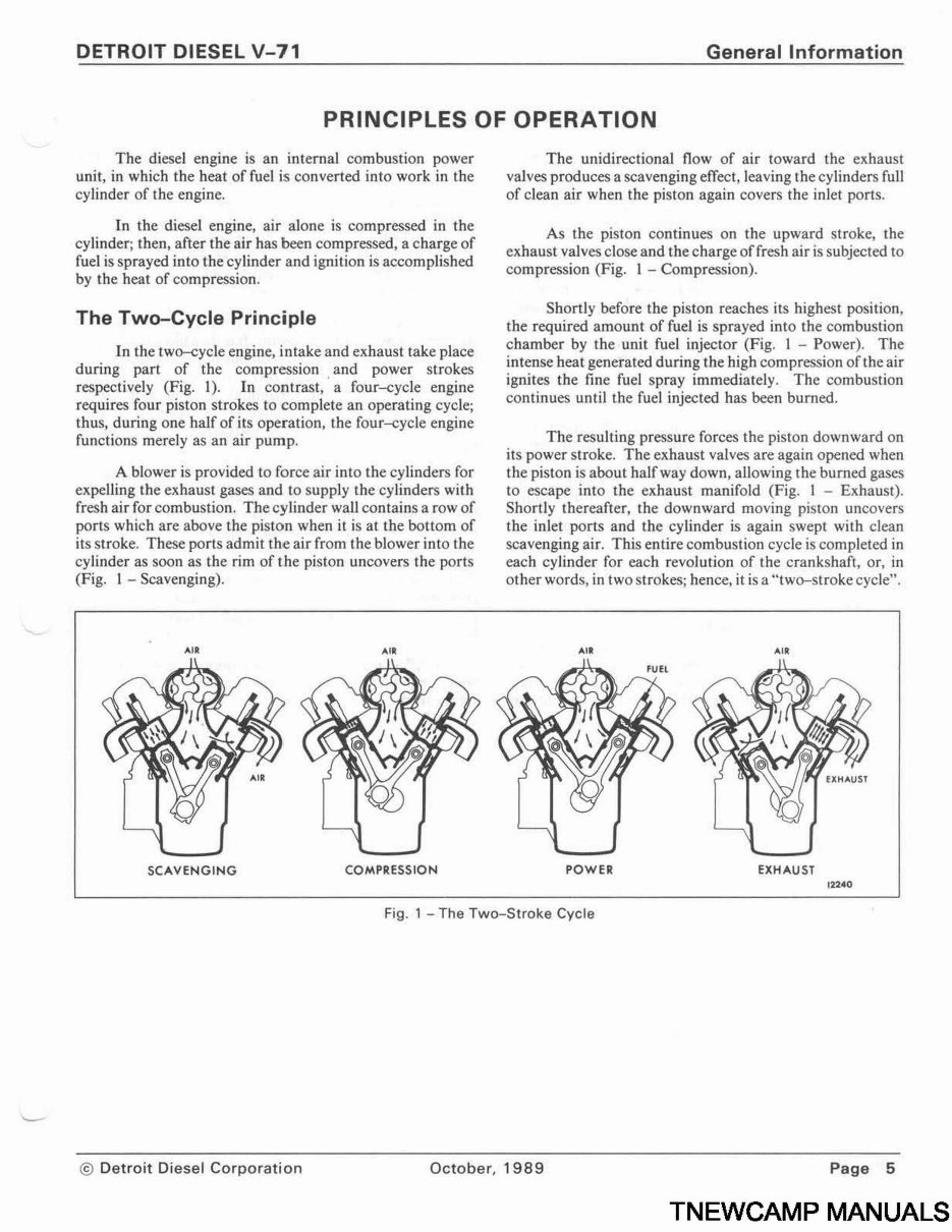
PRINCIPLES OF OPERATION
The die el engine is an internal combustion power
unit, in which the heat of fuel i converted into work in the
cylinder of the engine.
In the diesel engine, air alone is compressed in the
cylinder; then, after the air has been compressed, a charge of
fuel is sprayed into the cylinder and ignition is accomplished
by the heat of compression.
The Two-Cycle Principle
In the two-cycle engine, intake and exhau t take place
during part of the compres ion . and power strokes
re pectively (Fig. 1). In contrast, a four-cycle engine
require four piston strokes to complete an operating cycle;
thus, during one half of its operation, the four-cycle engine
functions merely as an air pump.
A blower is provided to force air into the cylinder for
expelling the exhaust gases and to upply the cylinders with
fresh air for combustion. The cylinder wall contains a row of
ports which are above the piston when it i at the bottom of
it troke. These ports admit the air from the blower into the
cylinder as soon a the rim of the piston uncover the ports
(Fig. I - Scavenging).
AIR AIR
SCAVENGING COMPRESSION
The unidirectional flow of air toward the exhaust
valves produces a scavenging effect, leaving the cylinders full
of clean air when the piston again covers the inlet ports.
A the piston continue on the upward stroke, the
exhaust valve close and the charge of fresh air i subjected to
compression (Fig. l - Compre sion).
Shortly before the piston reaches its highest po ition,
the required amount of fuel is prayed into the combu tion
chamber by the unit fuel injector (Fig. I - Power). The
inten e heat generated during the high compres ion of the air
ignite the fine fuel pray immediately. The combu tion
continues until the fuel injected has been burned.
The re ulting pressure forces the piston downward on
its power stroke. The exhau t valve are again opened when
the pi ton is about halfway down, allowing rhe burned gases
to e cape into the exhau t manifold (Fig. I - Exhaust).
Shortly thereafter, the downward moving pi ton uncover
the inlet ports and the cylinder i again wept with clean
cavenging air. Thi entire combu tion cycle i completed in
each cylinder for each revolution of the crank haft, or, in
other words, in two strokes; hence, it is a "two- troke cycle".
AIR AIR
POWER EXHAUST
1 2240
Fig. 1 - The Two-Stroke Cycle
© Detroit Diesel Corporation October, 1989 Page 5
TNEWCAMP MANUALS
General Information DETROIT DIESEL V-71
GENERAL DESCRIPTION
The two-cycle diesel engines covered in this manual
are produced in 6 8, 12 and 16 cylinder models having the
a.me bore and stroke and many of the major working parts
uch as injectors pistons, connecting rods, cylinder liner
and other part that are interchangeable.
AU cylinder blocks are ymmetrical in design thu
permitting oil cooler or starter installation on the same ide
or on opposite ides of the engine, depending upon the
installation requirements. The engines are built with
right-band or left-hand crankshaft rotation. For example
the crankshaft in an RC engine, viewed from the flywheel
end will rotate counterclockwise the oil cooler will be
mounted on the right-hand ·ide of the engine and the starter
will be on the left-hand ide (Fig. 2).
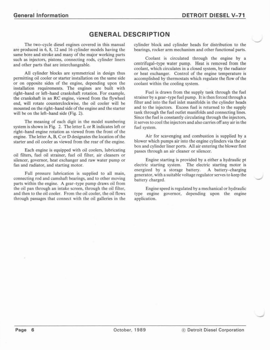
The meaning of each digit in the model numbering
ystem is hown in Fig. 2. The letter Lor R indicates left or
right-band engine rotation as viewed from the front of the
engine. The letter A, B, C or D designate the location of the
tarter and oil cooler as viewed from the rear of the engine.
Each engine is equipped with oil coolers, lubricating
oil filters fuel oil strainer, fuel oil filter, air cleaner or
ilencer, governor, heat exchanger and raw water pump or
fan and radiator, and tarting motor.
Full pres ure lubrication is upplied to all main,
connecting rod and cam haft bearings, and to other moving
part within the engine. A gear-type pump draw oil from
the oil pan through an intake creen, through the oil filter,
and then to the oil cooler. From the oil cooler, the oil flow
through pas age that connect with the oil galleries in the
cylinder block and cylinder head for distribution to the
bearing , rocker arm mechanism and other functional parts.
Coolant is circulated through the engine by a
centrifugaJ- type water pump. Heat i removed from tbe
coolant, which circulat in a clo ed y tern, by the radiator
or heat exchanger. Control of the engine temperature is
accompli hed by thermo tats which regulate the flow of the
coolant within the cooling system.
Fuel i drawn from the supply tank through the fuel
strainer by a gear-type fuel pump . It i then forced through a
ftlter and into the fuel inlet manifold in the cylinder heads
and to the injector . Excess fuel i returned to the upply
tank through the fuel outlet manifold and connecting lines.
Since the fuel is con tantly circulating through the injectors
it erv to cool the injector and also carries off any air in the
fuel y tern.
Air for cavenging and combustion is supplied by a
blower which pump air into the engine cylinder via the air
box and cylinder liner port . AU air entering the blower first
passes through an air cleaner or ilencer.
Engine starting i provided by a either a hydraulic pt
electric tarting sy ·tern. The electric starting motor is
energized by a storage battery. A battery-charging
generator, with a suitable voltage regulator erves to keep the
battery charged.
Engine speed i regulated by a mechanical or hydraulic
type engine governor, depending upon the engine
application.
Page 6 October, 1989 © Detroit Diesel Corporation
DETROIT DIESEL V-71
SEllES 71
V ENGINES
7
NUMBER
OF
CYLINDERS
0 8 2
APPLICATION
DESIGNATION
( see below l
APPLICATION DESIGNATIONS :
7081-7200 MAllNE
7083-7200 INDUSTRIAL F-F
7084 - 7200 POWER-BASE
7085-7200 GENERATOR
7087-1000 VEHICLE F·F
708_!·7000 VEHICLE H
BASIC ENGINE ARRANGEMENTS :
lololion : L Cleftl and R lrightl designatH rotation
viewed from th1t front of the engine
Type: A-B·C-D designate• location of starter and oil
cooler 01 viewed from the ~ CllywhHll end .
Cyllnd r Bonk: left ond right cylinder bonlts ore de ·
termlned from ~ of engine .
LA IXXXX-1 XXXI LB lXXXX· 2XXXI
IA l XXXX -S XXX I RB I XXXX - 6XXX I
-
General Information
7 2 0 1
BASIC ENGINE
AHANGEMENT
AND DllVE SHAFT
IOTATION
ltH below l
DESIGN
VARIATION
hub lowl
SPECIFIC
MODEL
NUMBER
DESIGN VARIATIONS :
7082 - 7000
7082 - 7100
7082 - 7200
7082-7300
7082 - 7400
7082-7500
7087 - 7600
7087 · 7100
7087 · 7!00
7087 · 7!00
V -7 1 " N " ENGINE
2 VALVE HEAD ENGINE
4 VALVE HEAD ENGINE
TURBOCHARGED ENGINE
TURBO·AFTERCOOLED ENGINE
CUSTOMER SPEC . ENGINE
CONSTANT HORSEPOWER ECONOMY (TAE)
(CALIFORNIA CERTIFIED)
CONSTANT HORSEPOWER ( TT }
CONSTANT HORSEPOWER f TTA )
(CALIFORNIA CERTIFIED)
CONSTANT HORSEPOWER ECONOMY (TTAE )
(CALIFORNIA CERTIFIED)
DRIVE SHAFT ROTATIONS :
7242 - 0200
7242-9200
LEFT-HAND
RIGHT-HAND
Dtive shaft rolatlon ; thoft rotation on multiple units
b det ermi ned fr om rhe reor of rhe unit.
lC IXXXX - 3XXX I lD lXXXX·4XXXl
RC lXXXX· 7XXX I RD I XXXX-8XXX I
All ABOVE VIEWS FROM REAR Of ENGINE
l ·l 1 •73
Fig. 2 - Model Numbering, Rotation and Accessory Arrangements
© Detroit Diesel Corporation October, 1989 Page 7
TNEWCAMP MANUALS
Genera I Information
6V
FRONT
0
0)
~
lot
z
z
0
<
o(
CV
CID
CID
I-
I- :t:
II..
~
w
@
....
©
Ci
( )
FIRING
ORDER
RH-1L - 3R - 3L-2R-2L-1 R
LH-1 l -1 R-2L-2R-3L-3R
c
8V
FRONT
0
Q)
0
0
@
@
©
©
FIRING
ORDER
)
RH -1 l- 3R-3L - 4R . 4L . 2R - 2L -1 R
LH -1 L-1 R-2l-2R -4l-4R-3l - 3R
~
z
<
CID
....
II..
w
_,
c
12V
FRONT
0
0
0
0
0
0
0
©
©
@
©
©
FIRING
ORDER
)
RH- ll - 5l - 3R-4R - 3l .4L
- 2R - 6R - 2L . 6L-1 R .5R
LH.1 l- 5R -1 R- 6L - 2L - 6R-
2R- AL . JL • .4R -3R-5l
DETROIT DIESEL V-71
:lot
z
<
<ID
....
....
w
_,
(
16V
FRONT
CD
CD
0
0
@
0
©
©
©
©
©
©
0
0
©
®
FIRING
ORDER
)
RH - 1L - 2R - 8L - 6R - 2L - 4R - 6L - 5R
. 4L . 3R . 5L . 7R -3L-1 R. 7l . 8R
11750
LH .1 L- SR - ll -1 R- 3l - 7R - 5L - 3R
. 4l - 5 R- 6l - 4R - 2L - 6R - 8l - 2R
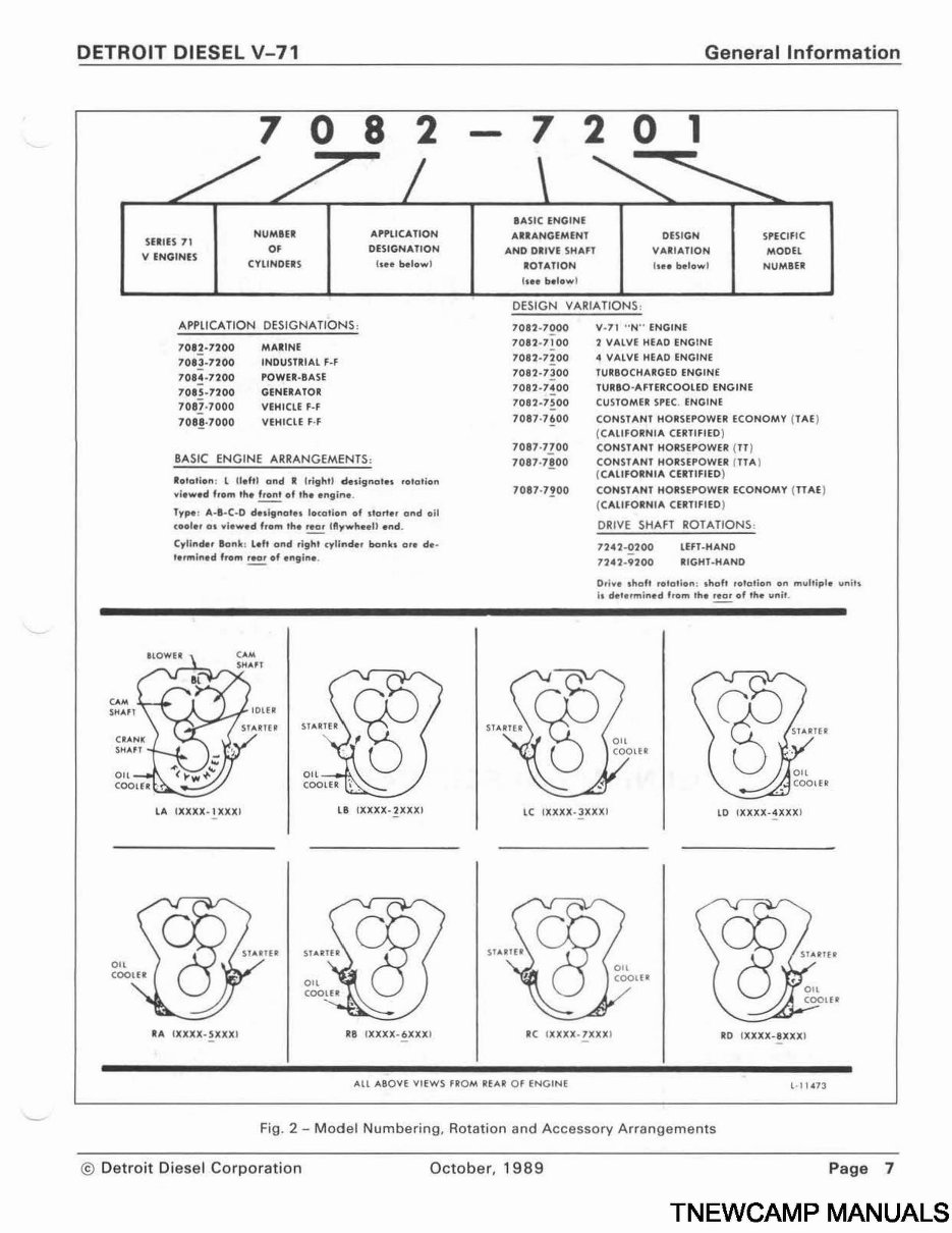
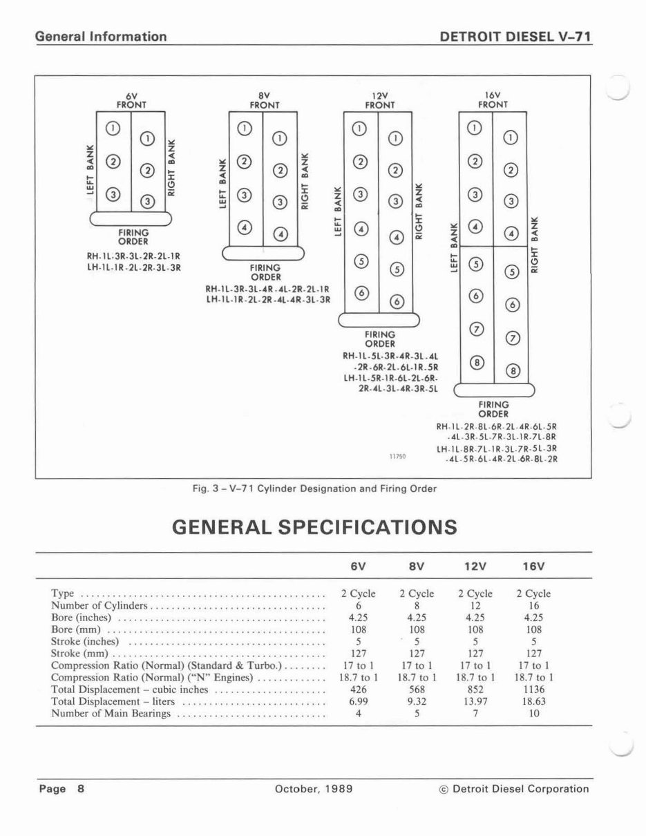
Fig. 3 - V-71 Cylinder Designation and Firing Order
GENERAL SPECIFICATIONS
Type ................. ... ............ . .. .. ..... . .. .
Number of Cylinders , .. . .. ... .... .... .. . .. .. ...... .. .
Bore (inches) .. . ..... . .......... . ..... . ............ .
Bore ( mm) ........... . ................ . ........... .
troke (inch ) . . . . . . . . . . . . . . . . . . . . . . . . . . . . . . . . . . . . .
Str oke ( mm ) .......... . ................ . .. . ........ .
Compr es ion Ratio Normal) (Standard & Turbo.) ....... .
Compression Ratio (Normal) ("N " Engine ) ...... . ..... .
Total Displacement - cubic inche ....... . .. . ......... .
Total Displacement - liter . .. . .. . ...... .. .... .. .. . . . .
Number of Main Bearings . . ............ . ............ .
6V
2 Cycle
6
4.25
108
5
127
17 to I
18.7 to l
426
6.99
4
Page 8 October, 1989
SV
2 Cycle
8
4. 25
108
5
127
17 to I
18 .7 to 1
568
9. 32
5
12V
2 Cycle
12
4.25
108
5
127
17 to I
18.7 to l
852
13 .97
7
16V
2 Cycle
16
4.25
108
5
127
17 to 1
18 .7 to I
1136
18 .63
10
© Detroit Diesel Corporation
DETROIT DIESEL V-71 General Information
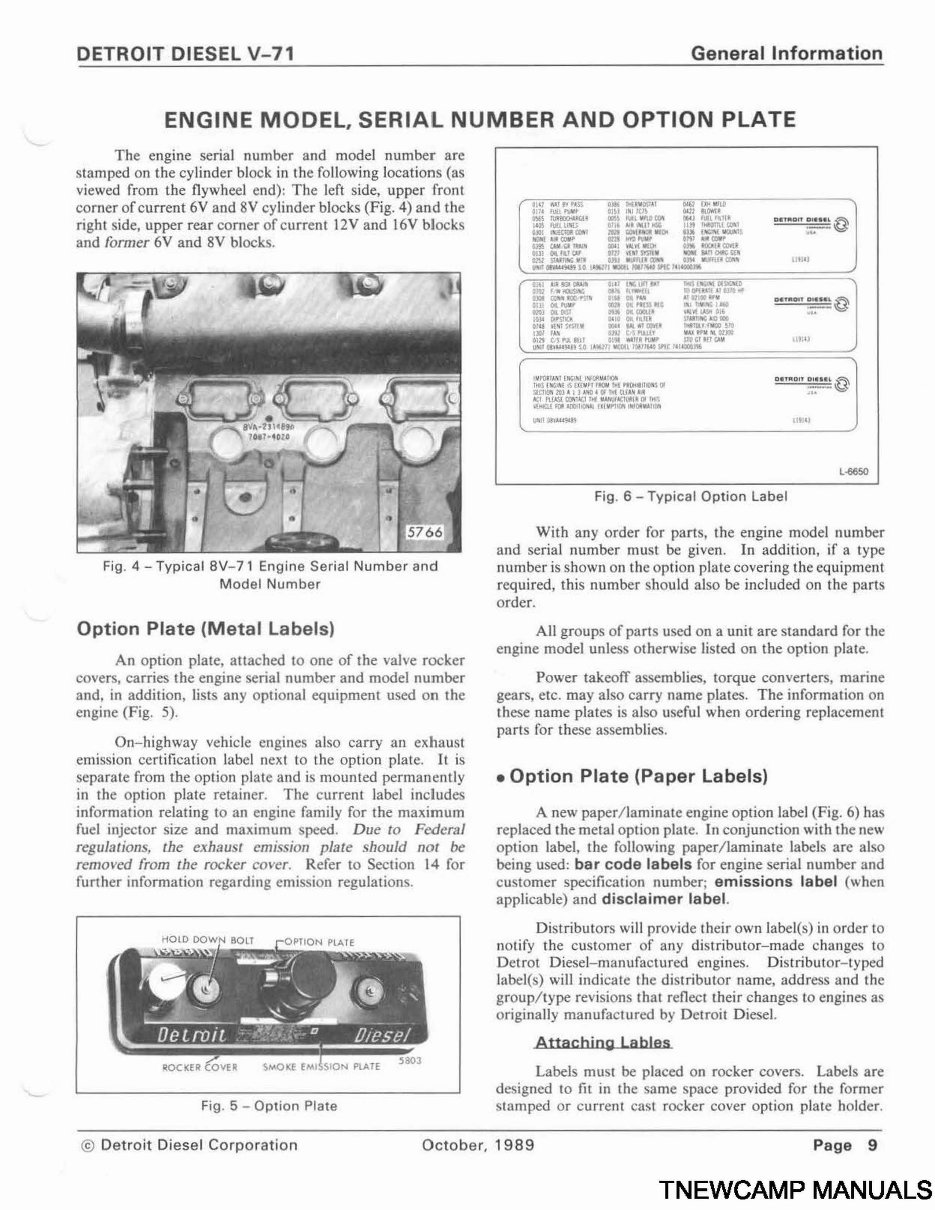
ENGINE MODEL, SERIAL NUMBER AND OPTION PLATE
The engine erial number and model number arc
tamped on the cylinder block in the following location (a
viewed from Lhe flywheel end): The left side, upper front
corner of current 6V and 8V cylinder block (Fig. 4) and the
right ide, upper rear comer of current I 2V and l 6V block
and former 6V and 8V block .
Fig. 4 - Typical BV-71 Engine Serial Number and
Model Number
Option Plate (Metal Labels)
An option plate, atta hed LO one of the val e rocker
c ver , carrie the engine erial number and model number
and, in addition, lj any optional equipment u ed on the
engine (Fig. 5).
On-highway vehicle engine also carry an exhau t
emi sion certification label next to the option plate. It i
eparate from the option plat and i mounted permanently
in the option plate retainer. The current label in lude
information relating to an engine family for the maximum
fuel injector ize and ma imum peed. Due to Federal
regulation , c.he exhau t cmi ion plate hould not be
removed from c.he rocker er . Refer to Section 14 for
further information regarding cmi i n regulation .
Fig. 5 - Option Plate
ltltJ
OOTOOfT 0tU4• j ~
. \g
•n:u
ae"'o tr ;;'"'@
L-6650
Fig. 6 - Typical Option Label
With any order for part , the engine model number
and erial number mu t be given. In addition if a type
number is shown on the option plate covering the equipment
required this number h uld al o be included on the parts
order .
AU group of part u ed on a unic are tandard for the
engine model unles otherwi e Ii ted on the option plate.
Power takeoff embli , torque con erter , marine
gear , etc. ma al o carry name plates. The information on
the e name plate i al o u eful when ordering repla ement
part for the e a embli .
•Option Plate (Paper Labels)
A new paper/ laminate engine option label (Fig. 6) has
replaced the metal option plate. In conjunction with the ne~
ption label the folio' ing paper/laminate label are al o
being u ed: bar code labels for engine erial number and
cu tomer pecification number; emissions label c~ hen
applicable) and disclaimer label.
Di tributor ' ill provide their own label(·) in order to
notify the cu ·tomer f any di tributor-made change lo
Detroc Diesel- manufa tured engines. Di tributor- lyped
label( ) will indicate the di tributor name, addre and the
group/type re i ion that reflect their changes to engine a
originally manufactured b Detroit Diesel.
Attaching Lables
Label mu t be pla ed on rocker cover . Label are
de igned to fit in the ame pace provided for the former
tamped or current ca. t rocker cover option plate holder.
© Detroit Diesel Corporation October, 1989 Page 9
TNEWCAMP MANUALS
You're Reading a Preview
What's Included?
Lifetime Access
Access PDF Contents & Bookmarks
Print one or all pages of your manual
Add to Cart
$41.99
$54.99