Detroit Series 60 & Series 50 Camshaft Timing Specifications
What's Included?
Lifetime Access
Fast Download Speeds
Online & Offline Access
Access PDF Contents & Bookmarks
Full Search Facility
Print one or all pages of your manual
No.: 04 TS-43Rev3 January 28, 2008 TO: Service Locations FROM: Technical Support Development SUBJECT: Series 60 ® and Series 50 ® Camshaft Timing Specifications ISSUE Camshaft timing, valve lash, injector height, and Jake Brake® lash are all very important specifications that must be followed closely in order to optimize the performance and service life of any Detroit Diesel engine. We have assembled four charts that bring together essential and current information for servicing the Series 60 and Series 50 diesel and gas engines. Most of the models listed in the attached charts are on-highway applications, but there are a few listed for off-highway. The attached camshaft timing charts should prove very helpful when servicing these engines. Note: If the valve cover option label is missing, illegible or incorrect you will need to check to see what camshaft is in the engine. To determine the camshaft that is used in the engine check the part number stamped on the rear face of the camshaft or use DDCSN to enter the engine serial number. DDCSN will retrieve the model number which will provide the correct injector and valve adjustments. CONTACT INFORMATION Please contact the Detroit Diesel Customer Support Center at 313-592-5800 or email csc@detroitdiesel.com if you have any questions. Detroit Diesel 13400 Outer Drive, West / Detroit, Michigan 48239-4001
The following is from the Series 60 Service Manual (6SE483). *** Adjust the valves and N3 fuel injector settings as follows: 1. Disconnect starting power for engine. 2. Remove the engine valve rocker cover as outlined. Refer to "Removal and Cleaning of One-piece Rocker Cover for Diesel Engines Only" for one-piece, refer to "Removal and Cleaning of Two-piece Rocker Cover for Diesel Engines Only" for two-piece rocker cover, and refer to "Removal and Cleaning of Three- piece Rocker Cover" for three-piece rocker cover. 3. Insert a 3/4 in. drive breaker bar or ratchet into the square hole in the center of the crankshaft pulley. 4. Bar the engine in the direction of rotation and observe a cylinder where the injector rocker arm is just beginning to depress the injector plunger, both the intake and exhaust valves should be closed. a. Stop turning the engine and mount a magnetic base dial indicator so you can monitor the upward lift of travel of that injector lobe. b. Set the pedestal of the dial indicator on the top of the injector cam roller. Adjust the pedestal so it can travel the entire upward movement of the lobe. c. Continue to slowly bar the engine over in the direction of rotation until the dial indicator shows no more upward lift. The needle of the dial indicator will stop moving indicating maximum lift. d. This is the point of maximum injector roller lift, the injector can now be set. e. If you rotate the engine beyond this point you will have to bar the engine over in the opposite direction at least 1/4 turn and then bar the engine over in the direction of rotation until maximum injector roller lift is obtained. 5. Stop engine rotation and note which cylinder this is, and follow the sequence listed in Table 1 to correctly set injector and valves. Max. injector lobe travel on Cylinder No. Adjust Injector on Cylinder No. Adjust Valves on Cylinder No. 6 6 2 2 2 4 4 4 1 1 1 5 5 5 3 3 3 6 Table 1. Valve Lash and N3 Injector Setting Adjustment Sequence
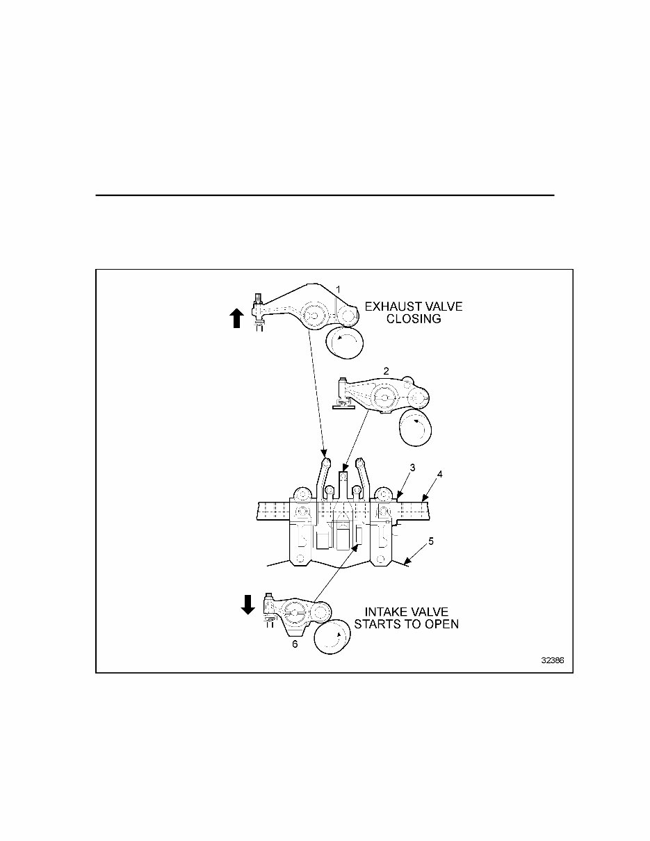
6. This injector can now be set using this procedure: a. Loosen the locknut on the adjusting screw at least two full turns. b. Tighten the adjusting screw until the injector plunger bottoms out; torque value should be 4.51 N·m (40 in·lbs). c. Back the adjusting screw off 3/4 of a turn 0.75 mm ± 0.25 mm (0.03 in.± 0.01 in.) and tighten the locknut to 41-47 N·m (30-35 lb·ft). d. The injector is now adjusted. The following is from the EPA07 Series 60 Service Manual (6SE2007). **** Valve Lash Adjustments and E3 Fuel Injector Setting 1. Exhaust Valve Rocker Arm Assembly 4. Rocker Arm Shaft 2. Fuel Injector Rocker Arm Assembly 5. Cylinder Head 3. Camshaft 6. Intake Rocker Arm Assembly Figure 1. Valve Overlap Period
Adjust the valves and fuel injector settings as follows: 1. Disconnect starting power for engine. 2. Remove the engine valve rocker cover as outlined. Refer to "Removal and Cleaning of Two-piece Rocker Cover for Diesel Engines Only" for two-piece rocker cover, and refer to "Removal and Cleaning of Three-piece Rocker Cover" for three-piece rocker cover. 3. Insert a 3/4 in. drive breaker bar or ratchet into the square hole in the center of the crankshaft pulley. 4. Bar the engine in the direction of rotation and observe a cylinder where the injector rocker arm is just beginning to depress the injector plunger, both the intake and exhaust valves should be closed. See Figure 1. a. Stop turning the engine and mount a magnetic base dial indicator so you can monitor the upward lift of travel of that injector lobe. b. Set the pedestal of the dial indicator on the top of the injector cam roller. Adjust the pedestal so it can travel the entire upward movement of the lobe. c. Continue to slowly bar the engine over in the direction of rotation until the dial indicator shows no more upward lift. The needle of the dial indicator will stop moving indicating maximum lift. d. This is the point of maximum injector roller lift, the injector can now be set. e. If you rotate the engine beyond this point you will have to bar the engine over in the opposite direction at least 1/4 turn and then bar the engine over in the direction of rotation until maximum injector roller lift is obtained. 5. Stop engine rotation and note which cylinder this is, and follow the sequence listed in Table "Valve Lash and Injector Setting Adjustment Sequence" to correctly set injector and valves. Max. injector lobe travel on Cylinder No. Adjust Injector on Cylinder No. Adjust Valves on Cylinder No. 6 6 2 2 2 4 4 4 1 1 1 5 5 5 3 3 3 6 Table 1. Valve Lash and Injector Setting Adjustment Sequence
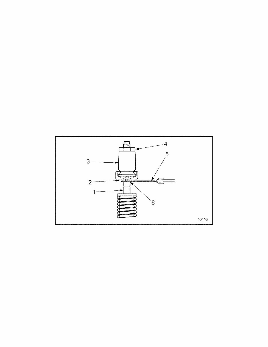
6. This injector can now be set using this procedure: a. Loosen the locknut on the adjusting screw at least two full turns. b. Tighten the adjusting screw until the injector plunger bottoms out; torque value should be 4.51 N·m (40 in·lbs). c. Back the adjusting screw off 3/4 of a turn 0.75 mm ± 0.25 mm (0.03 in.± 0.01in.) and tighten the locknut to 41-47 N·m (30-35 lb·ft). d. The injector is now adjusted. 7. Adjust the valves on the corresponding cylinders listed in Table "Valve Lash and Injector Setting Adjustment Sequence”. NOTICE: Never set the valves and injector of the same cylinder at the same time. Doing this will result in engine damage. 8. To adjust the intake valves, insert a 0.203 mm (0.008 in.) feeler gage between the tip of the valve stem and the valve button at the end of the rocker arm. See Figure 2. 1. Intake Valve 4. Locknut 2. Valve Button 5. Feeler Gage 3. Intake Rocker Arm Assembly 6. Tip of Intake Valve Figure 2. Intake Valve Adjustment 9. Loosen the locknut, and turn the adjusting set screw until the feeler gage produces an even smooth pull between the valve stem and valve button. 10. Torque the locknut to 41 - 47 N·m (30 - 35 lb·ft) and remove the feeler gage. Reinsert the feeler gage to ensure that the adjustment did not change when the locknut was tightened. Readjust as necessary.
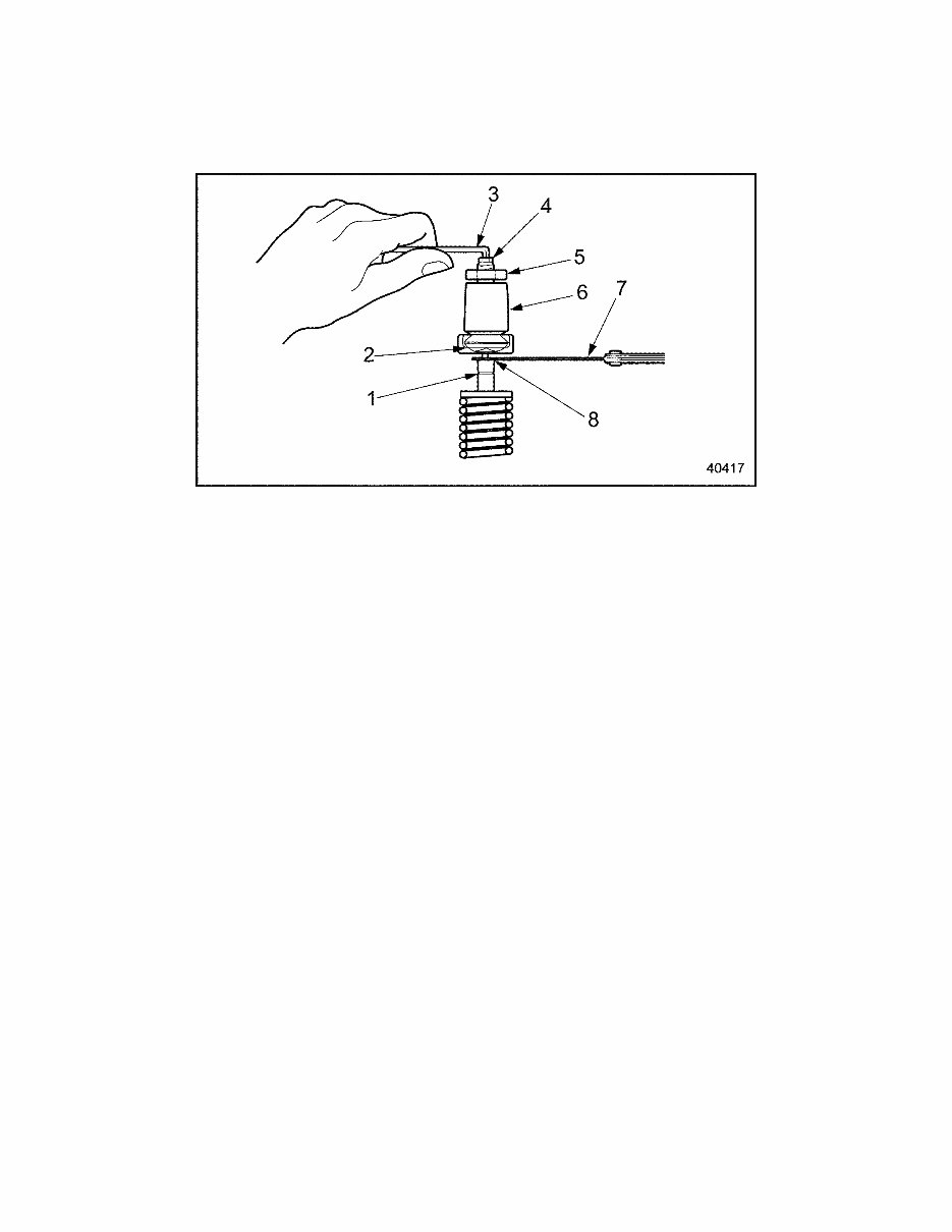
11. The exhaust valves are adjusted the same way as the intake valves, except use a 0.508 mm (0.020 in.) feeler gage. See Figure 3. 1. Location of Identification Groove 5. Locknut 2. Valve Button 6. Exhaust Rocker Arm Assembly 3. Allen Wrench 7. Feeler Gage 4. Adjusting Screw 8. Tip of Exhaust Valve Figure 3. Exhaust Valve Adjustment 12. Repeat steps 4-11 until all injectors and valves have been set. 13. Install the engine rocker cover. Refer to "Installation of Two-Piece and Three- Piece Rocker Covers" for two and three-piece rocker covers. 14. Reconnect starting power to the engine.
GK 8.5 1993-97 III 23519870 / 871 78.8 (3.103) 0.203 (0.008) 0.660 (0.026)* 750 0.660 (0.026) 5.21-6.27 (0.205-0.247) MK_E 8.5 2003-04 IV 23527028 / 029 81.0 (3.190) 0.203 (0.008) 0.508 (0.020) 750B 0.584 (0.023) 5.02-6.09 (0.198-0.240) 0.508 mm (0.020 in) lash setting. * May be equipped with newer replacement cylinder head 23529994 or R23529994 containing Pyromet exhaust valves that require a 0.508 mm (0.020 in) lash setting. Check cylinder head part number before servicing exhaust valve lash. 750A 0.584 (0.023) 5.54-6.60 (0.218-0.260) 80.3 (3.161) 0.203 (0.008) 0.660 (0.026)* 23522197 / 198 23524893 / 894 TK 8.5 1998-99 IV 23524421 / 422 23524915 / 916 81.0 (3.190) 0.203 (0.008) 0.660 (0.026)** 750 0.660 (0.026) 5.21-6.27 (0.205-0.247) MK,MK_E 8.5 1999-02 IV 750B 0.584 (0.023) 4.92-5.99 (0.194-0.236) 750 0.660 (0.026) 5.21-6.27 (0.205-0.247) GK 8.5 1993-97 III 78.8 (3.103) 0.203 (0.008) 78.2 (3.078) 0.203 (0.008) 0.508 (0.020) 23511364 / 785 23524895 / 896 23511364 / 785 23524895 / 896 0.660 (0.026)* GU 8.5 1993-97 II DDEC Jake Brake Lash mm (inches) Cam Timing Range mm (inches) ** Models MK and MK_E with serial numbers after 04R39213 were built with cylinder head 23529994, which contains Pyromet exhaust valves requiring a SERIES 50 DIESEL VALVE LASH, JAKE BRAKE LASH AND CAM TIMING SPECS Jake Brake Model Camshaft/Assembly Part Number Injector Height mm (inches) Intake Valve Lash mm (inches) Exhaust Valve Lash mm (inches) Model Engine Year
SERIES 50 GAS VALVE LASH AND CAM TIMING SPECS Model Engine Year DDEC Camshaft/Assembly Part Number Intake Valve Lash mm (inches) Exhaust Valve Lash mm (inches) Service Cam Timing Range mm (inches) GKG 8.5 1994-98 III 23519143 / 144 23524891 / 892 0.279 (0.011) 0.914 (0.036) 2.18-2.87 (0.086 -0.113) TKG 8.5 1998-02 IV 23519143 / 144 23524891 / 892 0.279 (0.011) 0.914 (0.036) 2.18-2.87 (0.086 -0.113) MKG 8.5 2002-04 IV 23530959 / 919 0.279 (0.011) 0.914 (0.036) 2.18-2.87 (0.086 -0.113) SERIES 60 GAS VALVE LASH AND CAM TIMING SPECS Model Engine Year DDEC Camshaft/Assembly Part Number Intake Valve Lash mm (inches) Exhaust Valve Lash mm (inches) Service Cam Timing Range mm (inches) TKG 12.7 1995-98 III 23520286 / 627 23524909 / 910 0.279 (0.011) 0.914 (0.036) 2.18-2.87 (0.086 -0.113) TKG 12.7 1998-04 IV 23520286 / 627 23524909 / 910 0.279 (0.011) 0.914 (0.036) 2.18-2.87 (0.086 -0.113)
The 2008 manual for Detroit Diesel Series 60 & Series 50 Camshaft Timing Specifications provides crucial information for optimizing the performance and service life of these engines. It includes specifications for camshaft timing, valve lash, injector height, and Jake Brake lash. These specifications are essential for both professional mechanics and DIY enthusiasts servicing Series 60 and Series 50 diesel and gas engines.
The manual features four charts that consolidate current information for servicing these engines, with most models being for on-highway applications and a few for off-highway. The attached camshaft timing charts are particularly valuable for engine servicing.
It's important to note that if the valve cover option label is missing, illegible, or incorrect, it is necessary to check the camshaft used in the engine. This can be determined by inspecting the part number stamped on the rear face of the camshaft or by using DDCSN to enter the engine serial number. DDCSN will retrieve the model number, which is crucial for correct injector and valve adjustments.
Recently Viewed
5,521,897Happy Clients
2,594,462eManuals
1,120,453Trusted Sellers
15Years in Business
Price:
Actual Price:
Detroit Series 60 & Series 50 Camshaft Timing Specifications