SERVICE & REPAIR INSTRUCTIONS TURF-TRUCKSTER ® DIESEL & GASOLINE ENGINES MANUAL TRANSMISSION Litho in U.S.A. 08/00 Revised 12/01 WARNING: If incorrectly used this machine can cause severe injury. Those who use and maintain the machine should be trained in its proper use, warned of its dangers and should read the entire manual before attempting to set up, operate, adjust or service the machine. ! CD-SRI-TRKMNL Copyright 2001 Textron Golf, Turf & Specialty Products “All rights reserved, including the right to reproduce this material or portions thereof in any form.” GOLF , TURF & SPECIALTY PRODUCTS Publication Registration Information, specifications, illustrations and procedures in this manual are based on information in effect at the time of publication. Product improvements and changes due to advancements of product design may not be included in this manual. This manual is reviewed and updated as required to include changes and product improve- ments. By returning the completed Registration below TGTSP will notify you when an update is available. Send Registration to: Textron Golf,Turf & Specialty Products P.O. Box 7708 11524 Wilmar Blvd. Charlotte, NC 28273 Litho Date: Company Name __________________________________________ Your Name ______________________________________________ Your E-mail Address ______________________________________ Address ________________________________________________ City, State __________________________________ Zip ________ Register Your CD Use the registration on back of tray card. Attn. Service Department Downloaded from www.Manualslib.com manuals search engine
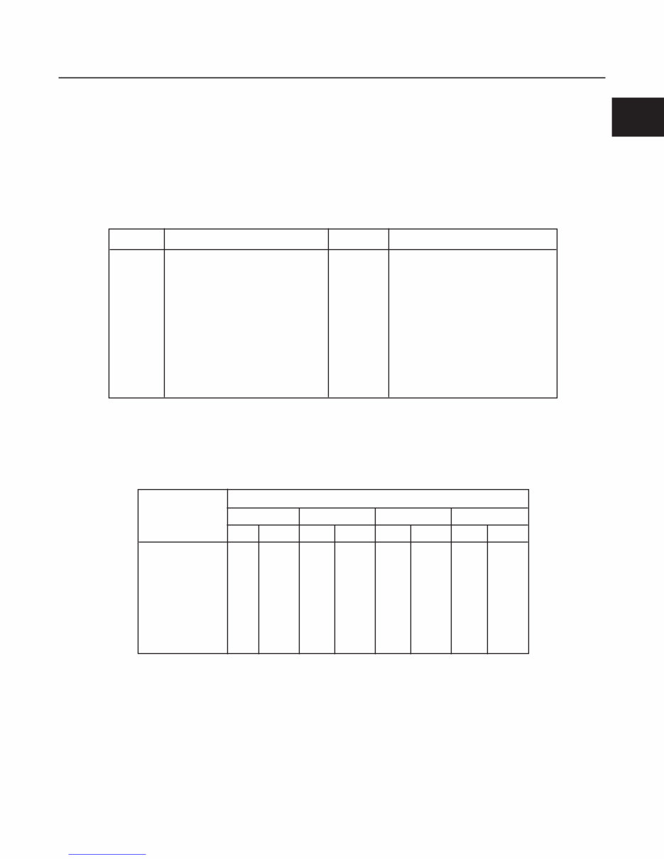
CONTENTS This manual contains repair instructions for truck com- ponents, attachments and options. The Table of Contents at the start of each section lists contents of that section. Sections are identified by tabs in the right hand margin. This manual is to be used in conjunction with appropri- ate operations and parts manuals for this equipment. This manual is for trucks equipped with hydraulic actu- ated dump boxes. Manuals covering optional acces- sories (such as sprayers and core harvesters) are list- ed in Section 13 of this manual. This manual covers models with engine and rear axle variations listed in the table below. Normal maintenance, adjustment, and operating proce- dures are also covered in the user operator’s manuals and are only included where appropriate in this manual. Engine repair is not covered in this manual. Refer to the appropriate engine manufacturer’s instructions for engine service and repair. This manual includes all removal, disassembly, inspec- tion, repair, reassembly, installation, adjustment, and testing procedures. If you, as user of this machine, do not consider yourself or your repair facilities capable of a given procedure, please consult your dealer or distributor. Information, specifications, illustrations, and procedures in this manual are based on information in effect at the time this manual was published. Improvements and product changes due to continual advancements of the product design may cause changes to your product that may not be included in this manual. Each manual is reviewed and updated as required to include changes and product improvements. Read each section completely before proceeding with specific repairs in that section. You will minimize errors by understanding what you will be doing and how the component relates to others in its system. Lists of repair tools and materials for each section of the man- ual are given at the start of that section. The designations L.H. (left hand) and R.H. (right hand) used throughout this manual refer to the operator’s left or right when sitting in the normal operating position. REGISTRATION A registration card is provided in the back of this man- ual (bottom portion of page). Fill out the card, remove and mail immediately upon opening the manual for the first time. The registration entitles you to receive manual updates for a period of two years. Updates are sent free of charge. NOTE Only the original registration card will be accept- ed. Photo copies, cards from other manuals, sug- gestion cards, or any facsimile are not acceptable and will not constitute a registration. INDEX NUMBERS Illustrations showing removal, disassembly, reassembly and installation may have index numbers to call out the sequence of procedure. Where the sequence of procedure is not important or self-evident (eg. linkages, hoses, clamps, etc.) index numbers are not included. Repair procedures for items not subject to wear (eg. panels, brackets, frames) are not included in this man- ual except for the general procedures given below. Exercise common sense during disassembly or reas- sembly; remove only the items required to accomplish necessary repair or service. INTRODUCTION SECTION 1A. GENERAL INFORMATION 1A-1 1A Engine Rear Axle Suzuki 660, 3-cylinder, gasoline, 31 hp (23.1 kW) at 4450 RPM, 2-speed hypoid, 6.7" (170 mm) clutch 14.21:1 ratio Suzuki 970, 4-cylinder, gasoline, 34 hp (25.4 kW) at 3600 RPM, 2-speed hypoid, 7.1" (180 mm) clutch 11.16:1 ratio Perkins 103-10, 3-cylinder, diesel, 22.3 hp (16.6 kW) at 3000 RPM, 2-speed hypoid, 7.1" (180 mm) clutch 11.16:1 ratio MODEL DIFFERENCES Downloaded from www.Manualslib.com manuals search engine
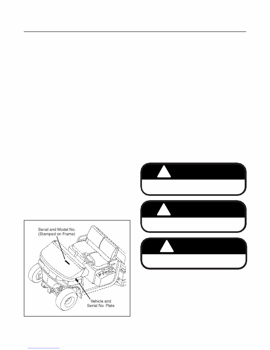
REPLACEMENT PARTS Use the appropriate parts manual when ordering re- placement parts. Follow installation instructions shipped with service parts or kits. When ordering parts, always give the model number and serial number of your machine as well as quantity, part number and descrip- tion of the parts needed (see Figure 1A-1 for model and serial number location). To eliminate error and speed delivery: 1. Write your NAME and ADDRESS on your order plainly. 2. Explain WHERE and HOW to make shipment. 3. Give MODEL (or PRODUCT) NUMBER, NAME and SERIAL NUMBER that is stamped on name and serial number plates on your unit. 4. Order by QUANTITY DESIRED, the PART NUM- BER and the DESCRIPTION OF PART. 5. Send your order to or visit your nearest AUTHO- RIZED TURF EQUIPMENT dealer and distributor. 6. INSPECT ALL SHIPMENTS ON RECEIPT. If any parts are damaged or missing, file a claim with the carrier before accepting. 7. Do not return material to your AUTHORIZED deal- er or distributor without a letter of explanation. Make a list of all returned parts, show your name and address, and include it with the shipment. TRANSPORTATION CHARGES MUST BE PRE- PAID. IDENTIFICATION NUMBERS See Figure 1A-1 for location of vehicle model and serial numbers. GENERAL CLEANING Improper cleaning and lubrication of your vehicle results in many equipment failures. Before any repairs are undertaken, thoroughly clean the exterior of the component to be removed. Use a clean surface to lay out parts being removed. Keep lubricants clean and cover containers not being used. Plug or cap all hydraulic lines and ports to hy- draulic components immediately after disconnecting. SAFETY Safety should always be the rule when working on or with machinery. Always use safe practices and com- mon sense when using hand or power tools. Use the suggested procedures in this manual when working with the vehicle. Throughout this manual signal words will be used to highlight special procedures. The signal words and their meaning are as follows: NOTE Any procedure needing special care when per- forming a procedure. Decals on the machine denote cautions, warnings and dangers. These cautions, warnings and danger decals must be on the machine at all times. If they become worn, torn or painted over, new decals should be in- stalled as shown in Section 14 of this manual. In addition to the decals on the vehicle, you must know and observe all cautions, warnings and danger precau- tions given in your vehicle’s Safety and Operation Manual(s). INTRODUCTION SECTION 1A. GENERAL INFORMATION 1A-2 Figure 1A-1. Identification ! CAUTION Hazards or unsafe practices which could result in personal injury or product or property damage. ! WARNING Hazards or unsafe practices which could result in severe personal injury or death. ! DANGER Imminent hazards which will result in severe per- sonal injury or death if precautions are not taken. Downloaded from www.Manualslib.com manuals search engine
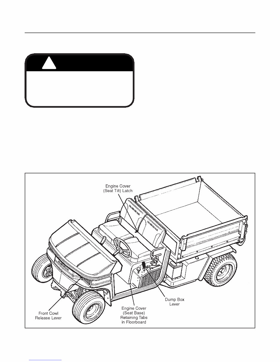
ACCESS LATCHES (See Figure 1A-2) ACCESS TO ENGINE For servicing the engine and related components, the engine cover can be tilted forward or removed. To gain access to the engine, push the engine cover latch to the rear of the unit, tilt cover forward. The latch is located at the center rear on top of the engine cover (between the seat cushion(s) and backwall). NOTE European market (CE compliant) vehicles have a key which is used to release a locking handle at the side of the engine cover latch. Turn the key to allow the latch to be pushed back. DUMP BOX RELEASE LEVER For servicing drive train and other components mounted under the dump box, pull back the dump box lever to extend the hydraulic cylinder and raise the dump box. Push forward on the dump box lever to lower the dump box. FRONT COWL ACCESS The front cowl opens to gain access to the fuse panel, the horn, the master cylinder reservoir as well as vari- ous access panels which when removed, allow access to the shifting lever linkage and front suspen- sion. To open the front cowl, locate the release lever next to the left side headlight. Pull the lever to the right to release the front cowl latch and at the same time pull up on the front cowl. Open the cowl allowing it to rest against the ROPS structure (if equipped) or the steering wheel. The front cowl will not “spring up” when the release lever is pulled. The cowl will have to be raised when the latch is released. INTRODUCTION SECTION 1A. GENERAL INFORMATION 1A-4 ! WARNING The engine cover is a MACHINERY GUARD and its removal exposes you to moving parts. Keep hands, hair and clothing away from fly- wheel, radiator cooling fan, alternator fan, engine belts, pulleys and air intake. Never remove or install the engine cover while engine is running. Figure 1A-2. Access Latches Downloaded from www.Manualslib.com manuals search engine
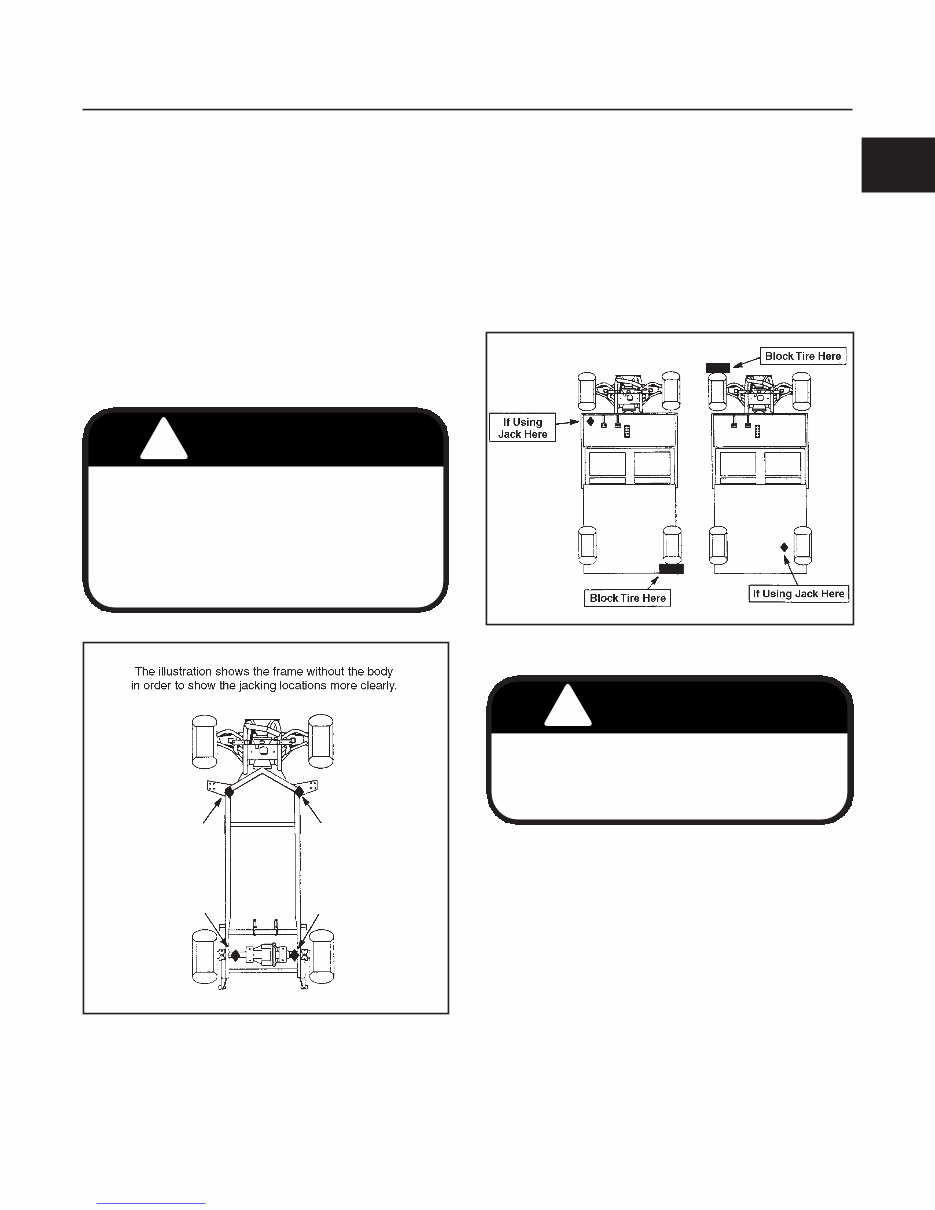
JACKS, JACKING LOCATIONS AND USING A HOIST A scissors type jack or a floor jack with a 1-1/2 ton (minimum) capacity that can be lowered to 3-3/8 inches (86 mm) height is required. The jacking locations are shown in Figure 1A-3. Put the gear selector in 1st gear. Apply the park brake. Raise the vehicle only enough to perform maintenance required. Place a jack in the appropriate location (see Figure 1A-3) and place a block behind (or in front) of the tire diagonally opposite the side which is being raised (see Figure 1A-4). Jack the vehicle to the appropriate height and place jack stands or equivalent support beneath the frame near the jack. Lower the jack and allow the vehicle to rest on the jack stands. Raise the vehicle only enough to perform the maintenance required. Make sure to block the tire diagonally opposite of the side which is being raised (see Figure 1A-4). When using a hoist to raise the vehicle, use the same procedure for supporting the frame and blocking the tires as you would when using a jack. INTRODUCTION SECTION 1A. GENERAL INFORMATION 1A-5 1A ! WARNING Do not rely solely on hydraulic or mechanical jacks for support. Use appropriate jack stands or equivalent for supporting the vehicle. If using a hoist, raise vehicle to appropriate height and support using jack stands or equivalent support. Never place feet, hands or any part of your body under the vehicle when raising it with a hoist. Figure 1A-3. Jacking Locations Figure 1A-4. Blocking ! CAUTION To prevent damage to the vehicle or attached accessory, never use a hoist to raise only one corner of the vehicle. Always raise both front or rear corners equally. Downloaded from www.Manualslib.com manuals search engine
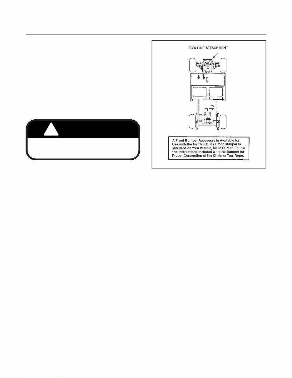
TOWING If for any reason the vehicle needs to be towed, follow the guidelines below to properly tow the vehicle. If towing the vehicle with a tow-rope or a chain, an operator is required to steer the vehicle and to control the brakes. Attach a tow line only to the front vertical frame mem- ber on either side of vehicle as shown in Figure 1A-5. Make sure the drive transmission is in “neutral” (out of gear) and the park brake is released. With the tow line attached, have the towing vehicle move forward until the tow line becomes tight. While towing, try to keep the tow line taut at all times. Be cautious going down inclines and while turning corners. INTRODUCTION SECTION 1A. GENERAL INFORMATION 1A-6 ! WARNING Never tow the vehicle faster than 5 M.P.H. (8 km/h). Towing at excessive speed could cause either vehicle to lose proper steering control. Figure 1A-5. Tow Line Attachment Locations Downloaded from www.Manualslib.com manuals search engine
Thank you for considering this comprehensive Service Repair Workshop Manual for the Cushman 4 Cycle 3 Cylinder Haulster Turf Truckster 327 Engine.
This manual is an invaluable resource for both professional mechanics and DIY enthusiasts, covering every service and repair procedure with easy-to-follow step-by-step instructions and detailed illustrations.
By utilizing this manual, you can save a substantial amount of money by performing your own repairs. It provides the flexibility to print specific pages, chapters, or the entire manual, and it can also be saved to your tablet for easy access.
All models, engines, trim, and transmission types are included in this manual, ensuring comprehensive coverage for all variations.
Key features of this high-quality Service Repair Workshop Manual include complete A-Z repair procedures, with every service and repair task thoroughly documented.
Compatibility is not an issue, as this manual is designed to work seamlessly on all PC and MAC computers, tablets, and mobile phones. The only software requirement is Adobe Reader, which can be obtained for free.
Upon payment confirmation via Visa, MasterCard, or PayPal, the manual will be instantly emailed to the address provided during checkout, ensuring prompt access to the valuable content.
Customer satisfaction is guaranteed, making this manual a reliable and essential tool for maintaining and repairing the Cushman 4 Cycle 3 Cylinder Haulster Turf Truckster 327 Engine.