CUMMINS N-855 NT-855 NTA-855 Series Engine Workshop Manual
What's Included?
Lifetime Access
Fast Download Speeds
Offline Viewing
Access Contents & Bookmarks
Full Search Facility
Print one or all pages of your manual
Product Manual 54088 (Revision NEW) Original Instructions 8924-604 Installation Kit for EPG 1712/1724 Electric Actuator on the Cummins N/NT/NTA-855 Engines Installation Manual
Manual 54088 8924-604 Kit on Cummins N/NT/NTA-855 Engines Woodward 1 8924-604 Installation Kit for EPG 1712/1724 on the Cummins N/NT/NTA-855 Engines Introduction These instructions apply to the EPG 1712/1724 (12 or 24 V) electric actuator manufactured by Woodward as mounted on a Cummins N/NT/NTA-855 engine driving a generator set. The mounting kit is Woodward part number 8924-604. The kit does not include the actuator, the wiring harness, or the magnetic pickup utilized by the electronic control system. The actuator, when mounted on the engine, operates the Cummins fuel (shutdown) shaft. Avoid pressure washing the EPG actuator, particularly the counterclockwise end of the actuator as water can enter the actuator through the sealed bearing. Actuator Mounting The following information should be used with Figure 2 to provide satisfactory installation of the actuator. Attach the actuator to the bracket as shown in the illustration. No gasket or washer is used between the actuator and the bracket surface. Torque the screws to 80 to 100 lb-in (9.0 to 11.3 Nm). Attach the mounting bracket and actuator assembly to the engine as shown. Note the direction of the rotation arrow. Linkage Instructions Assemble the rod ends and jam nuts on the 0.250-28 threaded rod. Do not tighten the jam nuts at this time. The rod does not work as a turnbuckle and it is necessary to turn a rod end for final adjustment of the length. The actuator will be at the minimum-fuel position. Attach the lever to the actuator shaft as shown (between 7 and 8 o’clock). Attach the new lever to the shutdown shaft. If manual or emergency shutdown systems are removed from the shutdown shaft to permit the electric actuator installation, they must be provided in other ways. The actuator lever should move a minimum of 25 degrees between minimum and maximum fuel (30 degrees will provide better stability). Response can be delayed if too little shaft movement is used, as this creates a deadband in the electronic control between the electrical signal and actual location of the actuator. If less than optimal rotation of the actuator shaft must be used, locate the lever so the actuator shaft approaches maximum-fuel stop on maximum-fuel signal. Adjust the shaft length and the rod end location in the two levers so the linkage lays about 10 degrees below flat at minimum fuel (shutdown).
8924-604 Kit on Cummins N/NT/NTA-855 Engines Manual 54088 2 Woodward When establishing the final length of the threaded rod, be sure about the same amount of rod is threaded into each rod end. At least five full threads of the threaded rod should be engaged in each rod end. Do not cause the rod ends to bind when tightening the jam nuts after establishing the proper rod length. The threaded rod could thread out of a rod end if it is not locked. Since the rod could move without changing speed control or stability until it comes loose, it is extremely important that the jam nuts on the threaded rod be kept tight. Wiring Suggestions If possible use 12 AWG (3.0 mm²), stranded, insulated wire in the circuit from the battery to the control and from the control to the actuator. 14 AWG (2.0 mm²) wire can be used but distances in the circuit must be shortened. Wires from the control to the actuator must be shielded. Use either shielded wire or twisted, three-conductor wire grounded at the control end only. Using 12 AWG (3.0 mm²) wire in the circuit for the 12 V actuator allows a maximum distance of 35 ft (11 m) from the control box to the actuator and 35 ft (11 m) from the battery to the control box. If 14 AWG (2.0 mm²) wire is used, the maximum distances are 10 ft (3 m) from the control box to the actuator and 10 ft (3 m) from the battery to the control box. The 24 V actuator will allow a maximum distance of 75 ft (23 m) from the control box to the actuator and 75 ft (23 m) from the battery to the control box. If 14 AWG (2.0 mm²) wire is used in the 24 V system, the maximum distance will be 35 ft (11 m) from the control box to the actuator and 35 ft (11 m) from the battery to the control box. The wire from the battery to the control must be direct from the battery posts to the control, not through a distribution point. The wire used must not be kinked, and ties should be of a non-conducting material. Use only new, well insulated, stranded wire in the installation. The wire is not supplied in the mounting kit, but special harnesses are available from Woodward. Wiring Terminal Fittings Attach AMP 52941 or AMP 52961 crimp-on number 6, slotted, insulated terminals or equivalent on the control-box end of 12 AWG (3.0 mm²) wires from the actuator and the battery. If 14 AWG (2.0 mm²) wire is used, attach AMP 52935 or AMP 52955 crimp-on slotted, number 6, insulated terminals or equivalent. The actuator end of the wires should be fitted with a number 8 ring terminal, AMP 35108 or equivalent for 12 AWG (3.0 mm²) wire, or AMP 32236 or equivalent for 14 AWG (2.0 mm²) wire. Polarity of the actuator connections is not important, and the wires can be interchanged. Protect the actuator electrical connections from accidental damage while servicing the engine.
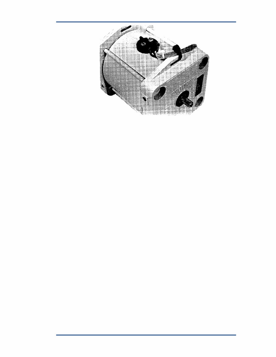
Manual 54088 8924-604 Kit on Cummins N/NT/NTA-855 Engines Woodward 3 Figure 1. Actuator with Wiring Attached (Note the tie of the actuator wire to the slot in the side of the actuator. The high- temperature tie included with the actuator should be used.)
This repair service manual is compatible with all Windows and Mac versions. You will need the Adobe Acrobat Reader to view the document as the manual is in PDF format. If you don't have this application, you can download and install it for free from the Adobe Acrobat website.
The file size of this manual is 87 MB, and it includes a parts catalog. It covers the following engine models:
This manual is presented in electronic format, allowing you to print out the pages you need and dispose of them when the task is completed. It contains detailed illustrations, step-by-step written instructions, necessary diagrams, and pictures. These manuals are a valuable source of repair and service information, suitable for both do-it-yourself enthusiasts and experienced mechanics worldwide. Using this repair manual is an inexpensive way to keep your vehicle working properly. The level of detail, along with illustrations, guides the reader through each service, repair, and maintenance procedure.
Recently Viewed
5,521,897Happy Clients
2,594,462eManuals
1,120,453Trusted Sellers
15Years in Business
Price:
Actual Price:
CUMMINS N-855 NT-855 NTA-855 Series Engine Workshop Manual