

CUMMINS ISX Wiring Diagram Manual
What's Included?
Fast Download Speeds
Online & Offline Access
Access PDF Contents & Bookmarks
Full Search Facility
Print one or all pages of your manual
OEM INTERFACES
CM570 ELECTRONIC SUBSYSTEM TECHNICAL PACKAGE
Cummins Engine Company, Inc. Page 1
WIRING DIAGRAM
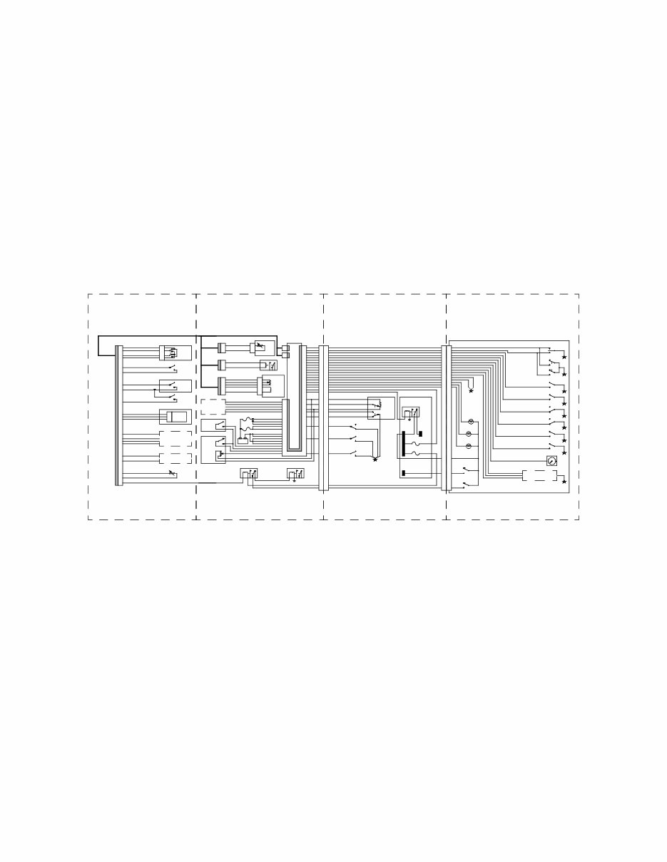
Layout. The CM570 Electronic Subsystem Wiring Diagram is organized into four sheets. Each sheet is one-fourth of
a single, continuous wiring diagram that defines every OEM interface to the CM570 electronic subsystem. The dia-
gram attempts to organize the components by location and interface. Actual locations may vary.
a. Sheet 1 shows every possible interface to the 31-pin OEM connector.
b. Sheet 2 shows every possible interface to the 50-pin OEM connector. Sheet 2 also shows interfaces to the
Water-In-Fuel (WIF) disconnect, the Engine Brake Relay disconnect, and the Electronic Air Compressor
Governor (E-Governor) disconnect.
c. Sheet 3 shows interfaces to OEM components typically located in the vehicle cab, except for the dashboard.
d. Sheet 4 shows interfaces to OEM components typically located in the dashboard.
Sheet 1 Sheet 2 Sheet 3 Sheet 4
31-Pin OEM
Connector
50-Pin OEM Connector
& Engine Compartment
Vehicle Cab
Except Dashboard
Dashboard
CM570 Electronic Subsystem Wiring Diagram Layout
OEM INTERFACES
CM570 ELECTRONIC SUBSYSTEM TECHNICAL PACKAGE
Cummins Engine Company, Inc. Page 2
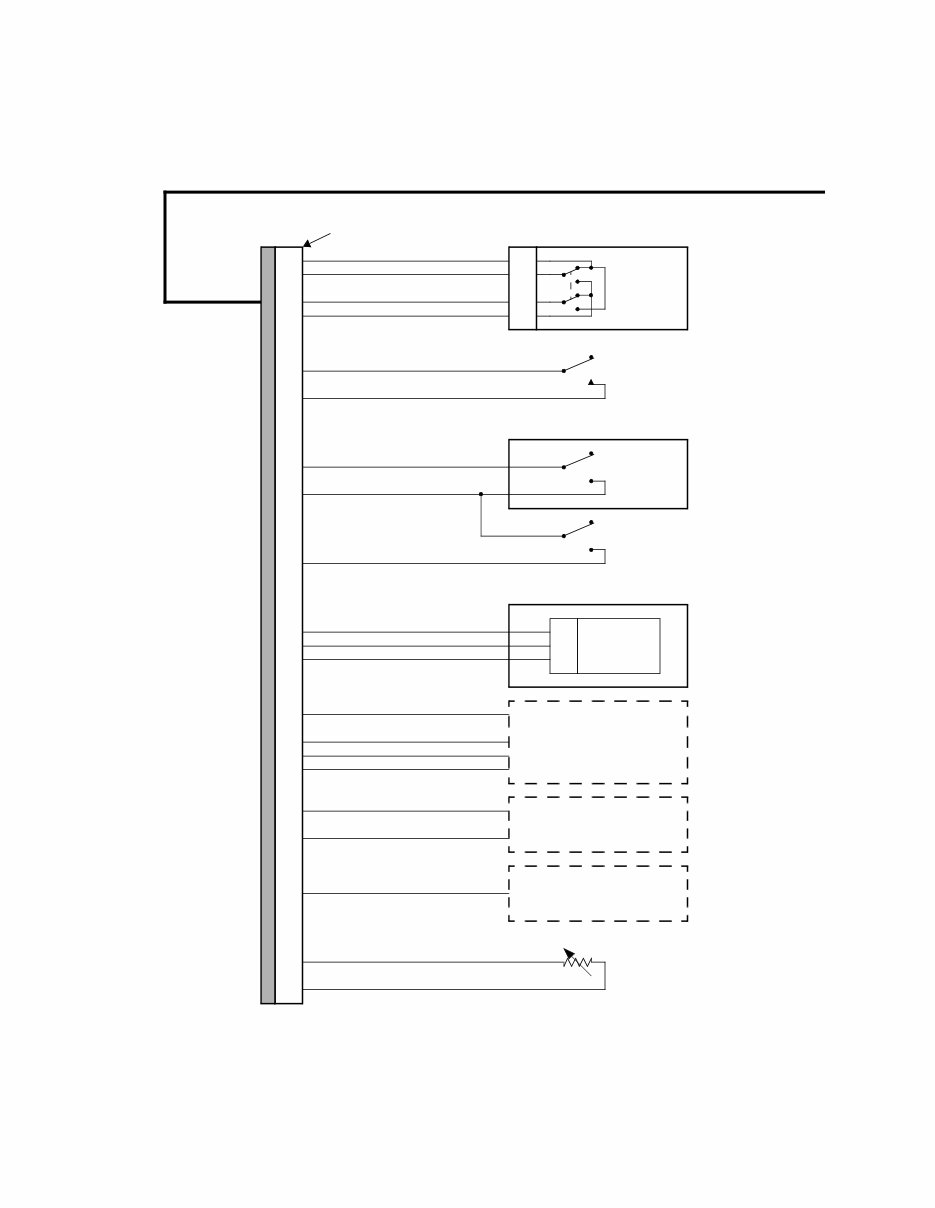
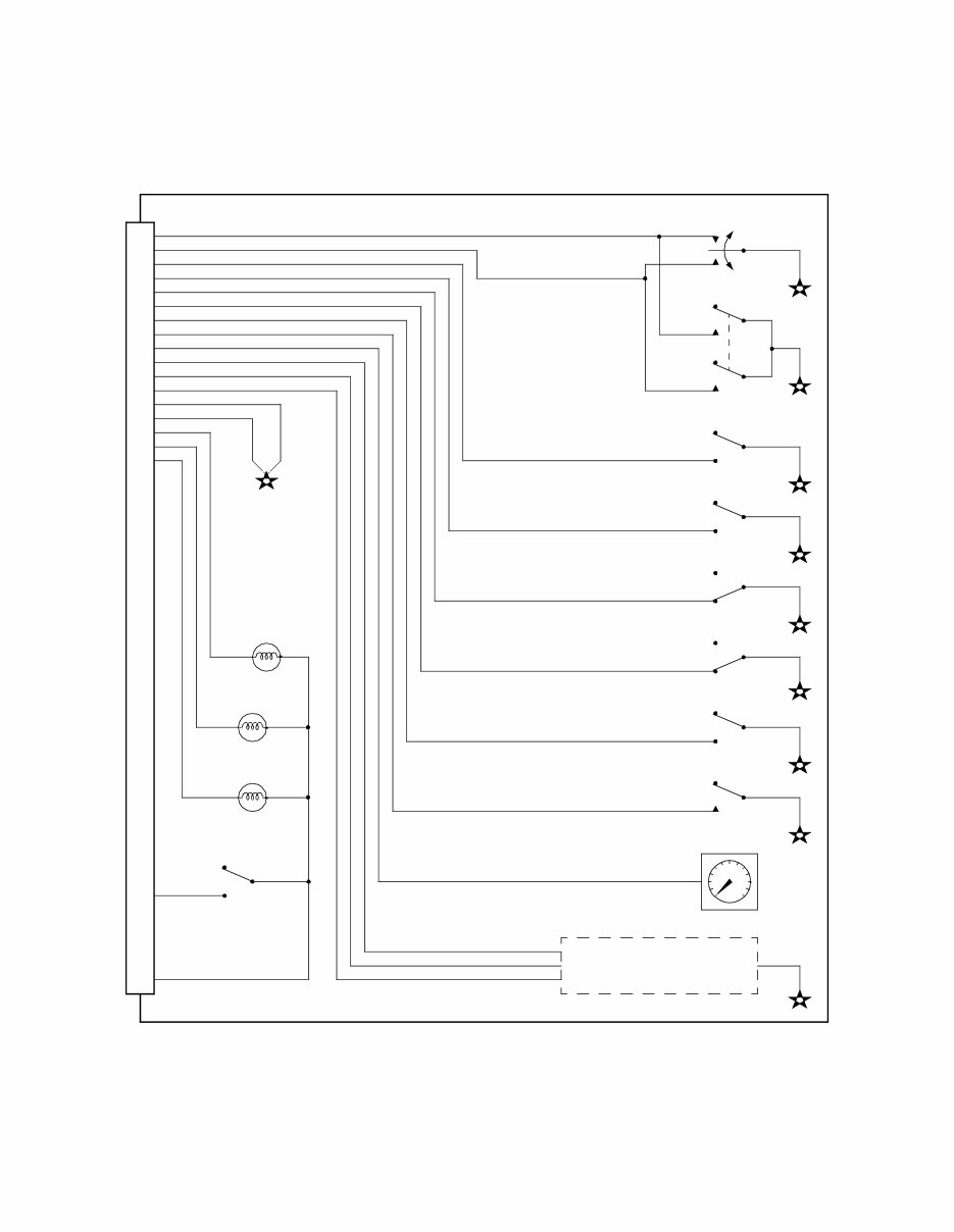
CM570 Electronic Subsystem Wiring Diagram - Sheet 1 of 4
Centinel Makeup Tank
Remote
Oil Level
Switch
Coolant
Level
Switch
A
B
C
D
Air Cond.
Pressure
Switch
Torque
Limit
Switch
24
30
8
11
9
6
19
7
5
17
18
25
4
22
21
15
12
16
13
20
A
B
C
Solenoid
Valve
See Fan Control
Wiring Options
See VSS
Wiring Options
Eaton Top-2 Transmission
31-Pin
General
Disconnect
31-Pin OEM Connector
COOLANT NOT DETECTED
COOLANT LEVEL RETURN
COOLANT LEVEL SUPPLY (+)
COOLANT DETECED
AC PRESSURE SWITCH
AC PRESSURE RETURN
ALTERNATE RETURN
TORQUE LIMIT SWITCH
REMOTE OIL LEVEL SWITCH
TOP2 LOCKOUT SOLENOID
FAN ON/OFF
FAN SIGNAL RETURN
IS TEMP
TACHOGRAPH
MAGNETIC PICKUP VSS(-)
TOP2 RETURN
TOP2 SHIFT SOLENOID
MECHANICAL VSS (-)
DIGITAL VSS (+)
MAGNETIC PICKUP VSS(+)
MECHANICAL VSS (+)
IS TEMP RETURN
FAN VARIABLE
STARTER LOCKOUT RELAY
3
Cummins Engine Harness
Pinouts not
used: 1, 2,
10, 14, 23,
26, 27, 28,
and 31.
Idle Shutdown
Temperature
Sensor
VSS RETURN
See Starter Lockout
Wiring Options
OEM INTERFACES
CM570 ELECTRONIC SUBSYSTEM TECHNICAL PACKAGE
Cummins Engine Company, Inc. Page 3
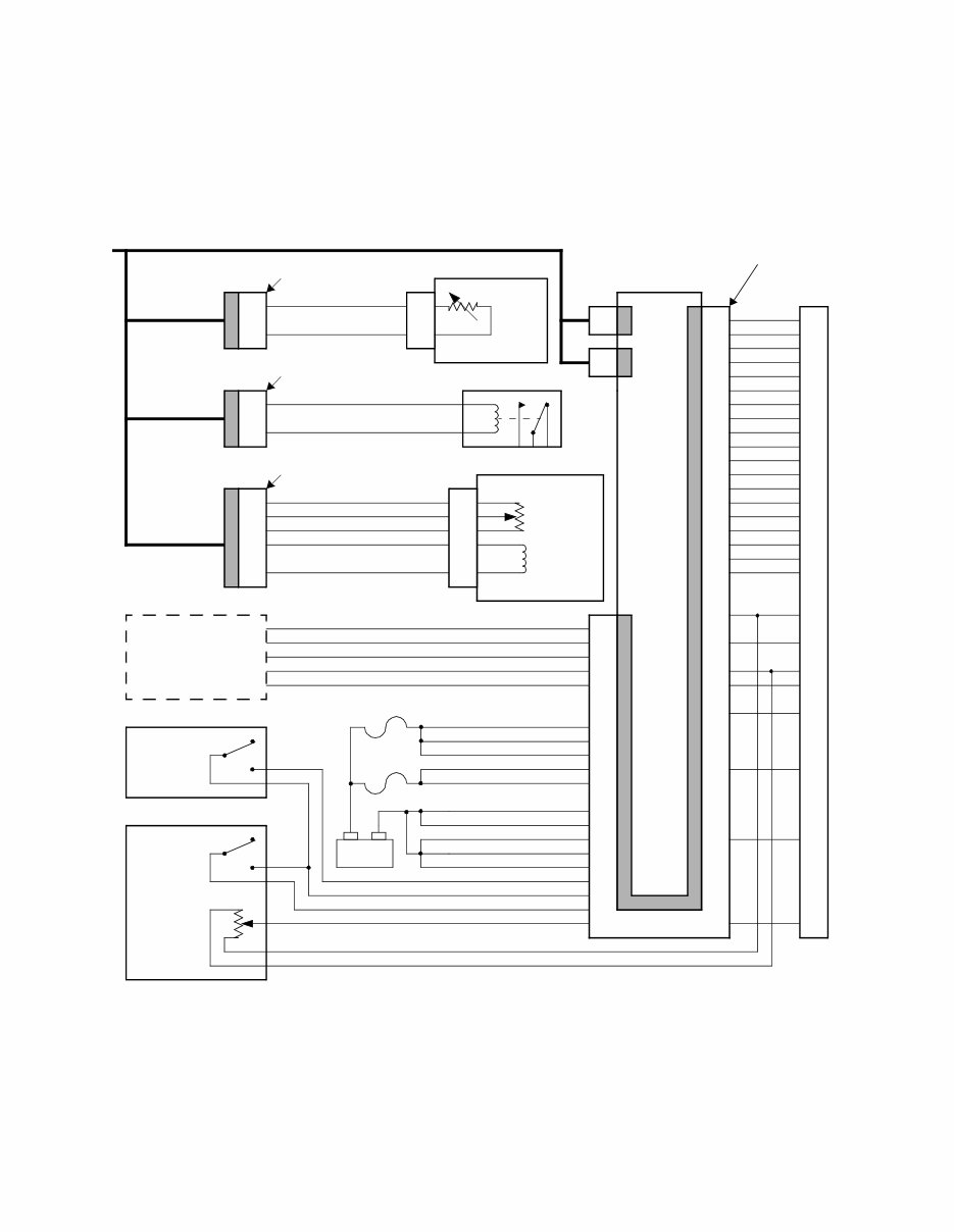
CM570 Electronic Subsystem Wiring Diagram - Sheet 2 of 4
- +
BATTERY
J1939 DATALINK (+)
J1939 DATALINK (-)
J1939 DATALINK SHIELD
J1587 DATALINK (+)
J1587 DATALINK (-)
REMOTE ACCEL. POSITION
REMOTE ACCEL. SWITCH
REMOTE RETURN
REMOTE PTO SWITCH
ECM SUPPLY (+)
ECM SUPPLY (+)
ECM SUPPLY (+)
ECM SUPPLY (+)
ECM SUPPLY RETURN
ECM SUPPLY RETURN
ECM SUPPLY RETURN
ECM SUPPLY RETURN
Position
Sensor
On/Off
Switch
Remote
PTO
Switch
37
36
7
8
17
29
28
18
39
30
40
50
34
20
43
21
ECM SUPPLY (+)
ECM SUPPLY RETURN
ACCELERATOR SUPPLY RETURN
ACCELERATOR SUPPLY (+)
Remote PTO Panel
Remote Accel. Panel
C1 C2
C3
1
2
1
2
WIF
Sensor
Fuel Filter
1
2
Engine Brake Relay
WIF Extension Harness
WIF
Disconnect
E-Governor
Disconnect
WIF SENSOR RETURN
WIF SENSOR
ENGINE BRAKE RELAY RETURN
ENGINE BRAKE RELAY
Engine
Brake
Relay
Disconnect
Engine Brake Relay Connector
Bulkhead
Connector
Electronic
Control Module
E-Governor Extension Harness
ISM Only
5
38
35
47
49
48
13
3
14
24
23
44
41
12
25
11
22
15
10
9
32
31
16
6
1
2
42
See Datalink Inter-
face Connector
Wiring Options
15A @ 12V
10A @ 24V
15A @ 12V
10A @ 24V
26
27
46
1
2
3
5
4
6
5
38
35
47
49
48
13
3
14
24
23
44
41
12
25
11
22
15
10
9
32
31
16
6
1
2
42
Cummins Engine Harness
50-Pin OEM
Connector
Air
Pressure
Sensor
Air
Control
Valve
E-GOVERNOR VALVE
E-GOVERNOR VALVE RETURN
WET TANK PRESSURE
WET TANK SUPPLY RETURN
WET TANK SUPPLY (+)
1
2
3
5
4
6
E-Governor
OEM INTERFACES
CM570 ELECTRONIC SUBSYSTEM TECHNICAL PACKAGE
Cummins Engine Company, Inc. Page 4
CM570 Electronic Subsystem Wiring Diagram - Sheet 3 of 4
Bulkhead
Connector
Dashboard
Disconnect
ECM Key On, 5A
Battery
Bus
Ignition
Bus
Switched
Bus
Idle Shutdown
Relay
Fuse Panel
IDLE SHUTDOWN RELAY
KEYSWITCH
WARNING LAMP
STOP LAMP
MAINTENANCE LAMP
Position
Sensor
Idle
ACCELERATOR SUPPLY (+)
CAB ACCELERATOR POSITION
ACCELERATOR SUPPLY RETURN
OFF IDLE SWITCH
ON IDLE SWITCH
CLUTCH SWITCH
SERVICE BRAKE
Service Brake
Clutch
Accelerator Assembly
Accelerator
ACCELERATOR
CAB RETURN 1
CAB RETURN 2
5
38
35
47
49
48
13
3
14
24
23
44
41
12
25
11
22
15
10
9
32
31
16
6
1
2
42
DIAGNOSTICS / CAB PTO / ALTERNATE PTO / IDLE / RSG / CRUISE: SET
DIAGNOSTICS / CAB PTO / ALTERNATE PTO / IDLE / RSG / CRUISE: RESUME
CRUISE ENABLE/ CAB PTO ENABLE / TOP2 ENABLE / IDLE ADJUST DISABLE / RSG ADJUST DISABLE
DIAGNOSTICS ENABLE / MANUAL SNAPSHOT
MAX ENGINE SPEED SWITCH
FAN ACCESSORY SWITCH
ACCELERATOR GOVERNOR SWITCH
EP SHUTDOWN OVERRIDE SWITCH
TACHOMETER
ENGINE BRAKE ISM1/ISX1
ENGINE BRAKE ISM2/ISX2
SWITCH
INTERLOCK
SWITCH
Interlock
ENGINE BRAKE ISX3
to Isolated
ECM Switch
Common
Validation
Switches
5
14
24
23
44
41
12
25
11
22
15
10
9
32
31
16
6
KS
B+
OEM INTERFACES
CM570 ELECTRONIC SUBSYSTEM TECHNICAL PACKAGE
Cummins Engine Company, Inc. Page 5
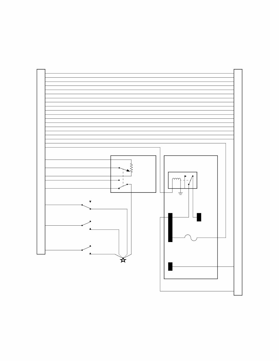
CM570 Electronic Subsystem Wiring Diagram - Sheet 4 of 4
See Engine Brake Switch
Wiring Options
ACCELERATOR GOVERNOR SWITCH
CRUISE ENABLE
DIAGNOSTICS ENABLE
FAN ACCESSORY SWITCH
MAX ENGINE SPEED SWITCH
EP SHUTDOWN OVERRIDE SWITCH
TACHOMETER
Tachometer
MANUAL SNAPSHOT
IDLE ADJUST DISABLE
CAB & ALTERNATE PTO ENABLE
RSG ADJUST DISABLE
TOP2 ENABLE
Maintenance
Stop
Warning
Keyswitch
SET
RESUME
Diagnostics On/Off
Max Engine Speed
Fan Accessory
Accelerator Governor
EP Shutdown Override
CC/PTO On/Off
PTO Additional
Set/Resume
Isolated
ECM Switch
Common
ENGINE BRAKE ISM1/ISX1
ENGINE BRAKE ISM2/ISX2
5
14
24
23
44
41
12
25
11
22
15
10
9
32
31
16
6
KS
B+
Dashboard Disconnect
Dashboard
ENGINE BRAKE ISX3
Source
DIAGNOSTICS / CAB PTO
ALTERNATE PTO / IDLE
RSG / CRUISE: RESUME
DIAGNOSTICS / CAB PTO
ALTERNATE PTO / IDLE
RSG / CRUISE: SET
You're Reading a Preview
What's Included?
Fast Download Speeds
Online & Offline Access
Access PDF Contents & Bookmarks
Full Search Facility
Print one or all pages of your manual
$41.99
Viewed 45 Times Today


Secure transaction
What's Included?
Fast Download Speeds
Online & Offline Access
Access PDF Contents & Bookmarks
Full Search Facility
Print one or all pages of your manual
$41.99
Discover the Cummins ISX Wiring Diagram Manual, a comprehensive resource tailored for the CM570 Electronic Subsystem Technical Package. This manual offers detailed wiring diagrams and instructions to effectively navigate the intricate electronic subsystems of the Cummins ISX engine.
Whether you're a professional mechanic or a DIY enthusiast, this manual is designed to cater to your needs, providing valuable insights to enhance your understanding and troubleshooting capabilities.


