

Continental engine overhaul service manual IO-520 IO520
What's Included?
Fast Download Speeds
Online & Offline Access
Access PDF Contents & Bookmarks
Full Search Facility
Print one or all pages of your manual

Publication X30039
©
2011 CONTINENTAL MOTORS, INC. AUG 2011
IO-520
CONTINENTAL
®
AIRCRAFT ENGINE
OVERHAUL
MANUAL
TECHNICAL CONTENT ACCEPTED BY THE FAA
A IO-520 Series Engine Overhaul Manual
31 August 2011
Supersedure Notice
This manual revision replaces the front cover and list of effective pages for Publication Part No. X30039, dated
September 1977. Previous editions are obsolete upon release of this manual.
Effective Changes for this Manual
0 .......... September 1977
1 ............ 31 August 2011
List of Effective Pages
Document Title: IO-520 Series Engine Overhaul Manual
Publication Number: X30039 Initial Publication Date: September 1977
Page Change Page Change Page Change Page Change
Cover ............................ 1
A ................................... 1
i thru v .......................... 0
1-1 thru 1-10................. 0
2-1 thru 2-10................. 0
3-1 thru 3-2................... 0
4-1 thru 4-30................. 0
5-1 thru 5-12................. 0
6-1 thru 6-30................. 0
7-1 thru 7-8................... 0
8-1 thru 8-20................. 0
9-1 thru 9-8................... 0
10-1 thru 10-2............... 0
Published and printed in the U.S.A. by Continental Motors, Inc.
Available exclusively from the publisher: P.O. Box 90, Mobile, AL 36601
Copyright © 2011 Continental Motors, Inc. All rights reserved. This material may not be reprinted, republished, broadcast, or otherwise
altered without the publisher's written permission. This manual is provided without express, statutory, or implied warranties. The publisher will
not be held liable for any damages caused by or alleged to be caused by use, misuse, abuse, or misinterpretation of the contents. Content is
subject to change without notice. Other products and companies mentioned herein may be trademarks of the respective owners.
i
iv October 1978
October 1978 v

Intentionally Left Blank

MAY 1980 1-1
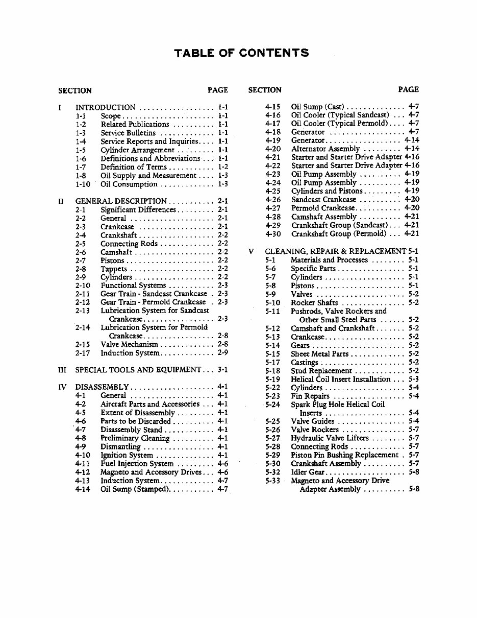
SECTION I
INTRODUCTION
1-1. SCOPE. This publication comprises
Overhaul Instructions for the IO-520 Series Aircraft
Engines.
1-2. RELATED PUBLICATIONS. Detail part
numbers and service assemblies for these engine
models are contained in Parts Catalog X-30040A.
Operating instructions are contained in Operator's
Handbook X-30041.
a. Service instructions for Slick Magneto Model
No. 662 may be obtained from Slick Electro Inc.,
Rockford, Illinois 61100.
b. Service instructions for Bendix Magneto
Model S6RN-201, S6RN-205, S6RN-1201 and
S6RN-1205 may be obtained from Bendix
Corporation, Electrical Components Division,
Sidney, New York 13830.
c. Service instructions for Delco-Remy Starters,
Generators or Alternators may be obtained from
Delco-Remy Division, General Motors Corporation,
Anderson, Indiana 96011.
1-3. SERVICE BULLETINS. Important
changes and product improvements are covered by
factory service bulletins available for study at all
Approved Distributors. These Bulletins are also
available to owners, operators or maintenance
personnel on an annual subscription basis.
1-4. SERVICE REPORTS AND INQUIRIES.
It is the policy of Teledyne Continental Motors to
handle all reports of service difficulty and requests
for information through Approved Distributors.
Request for further copies of this or any other
Teledyne Continental Aircraft Engine Service
Publication should be made through these facilities.
There is an Approved Distributor at every major
airport.
1-5. CYLINDER ARRANGEMENT. Cylinders
are numbered starting from the rear, with odd
numbers on the right and even numbers on the left.
1-6. DEFINITIONS AND ABBREVIATIONS
Term . Explanation
A.B.C. After Bottom Center
Approx. Approximately
A.T.C. After Top Center
Bar. Barometric
B.B.C. Before Bottom Center
B.H.P. Brake horsepower
B. T.C. Before Top Center
F.A.A. Federal Aviation Administration
C.A.R. Civil Air Regulations
c.f.m. Cubic feet per minute
C.G. Center of Gravity
Dia. Diameter
° Degrees of Angle
°F. Degrees Farenheit
Fig. Figure (Illustration)
Front Propeller End
ft. foot or feet
G.P .M. Gallons per minute
H2O Water
Hg. Mercury
I.D. Inside Diameter
in. (") Inches
Hex. Hexagon
hr. Hour
Left Side Side on which Nos. 2, 4 and
6 cylinders are located
Lbs. Pounds
Lockwire Soft steel wire used to safety
connections, etc.
Man. Manifold or manometer
Max. Maximum
Min. Minimum
30' thirty minutes of angle
(60' equal one degree)
N.P.T. National pipe thread
(tapered)

1-2
Term . Explanation
N.C. National Coarse (thread)
N.F. National Fine (thread)
O.D. Outside Diameter
Press. Pressure
p.s.i. Pounds per square inch
Rear Accessory end of engine
Right Side Side on which Nos. 1, 3 and
5 cylinders are located
R.P.M. Revolution per minute
Std. Standard
T.D.C. Top dead center
Temp. Temperature
Torque Force x lever arm (125 ft.-lbs.
force applied one ft. from bolt
center or 62-1/2 lbs. applied
2 ft. from center)
TABLE I. PURCHASED ACCESSORIES
ACCESSORY QTY
Magneto ....................................................................... 2
Starter .......................................................................... 1
Alternator ..................................................................... 1
Generator ..................................................................... 1
Oil Cooler ..................................................................... 1
Fuel Pump.................................................................... 1
Spark Plugs................................................................ 12
TABLE II. IGNITION SYSTEM DETAILS
FEATURE VALUE
Left Magneto Fires ............................... Lower No. 1-3-5
And Upper No. 2-4-6 plugs
Right Magneto Fires ............................. Upper No. 1-3-5
And Lower No. 2-4-6 plugs
Firing order (cylinder numbers) .................... 1-6-3-2-5-4
Permissible RPM spread when
Switched from “Both” to either
“Left” or “Right” magneto ............................................ 50
1-7. DEFINITION OF TERMS. Front, rear, left
and right, as used in this manual, refer to the engine
as viewed by the mechanic in a normal position,
facing the accessory end.
TABLE III.
CHARACTERISTICS AND DIMENSIONS
DIMENSION VALUE
Piston stokes per cylinder ............................................ 4
Number of cylinders ..................................................... 6
Cylinder bore (inches) ............................................. 5.25
Piston stroke (inches) ............................................. 4.00
TABLE IV. TEMPERATURE LIMITS
INDICATED CONDITION MIN. MAX.
Oil temperature at takeoff 75°F --
Oil temperature in flight -- 240°F.
Cylinder head temperature
(bayonet thermocouple)* -- 460°F.
Magneto temperature
(at coil hold-down screw) -- 170°F.
* Installed in tapped hole in bottom of cylinder head.
TABLE V. PRESSURE LIMITS
INDICATION MIN. MAX.
Oil pressure (idling) 10 psi --
Oil pressure (in flight) 30 psi 60 psi
Oil pressure (with cold oil) -- 100 psi
TABLE VI. VISCOSITY OIL GRADES
OIL OPERATING OIL
TEMPERATURE GRADE
Below 40°F. 30 OR 10W-30
Above 40°F. 50
Ambient air temperature is the controlling factor on all
engines having oil temperature control valves installed.
You're Reading a Preview
What's Included?
Fast Download Speeds
Online & Offline Access
Access PDF Contents & Bookmarks
Full Search Facility
Print one or all pages of your manual
$35.99
Viewed 19 Times Today


Secure transaction
What's Included?
Fast Download Speeds
Online & Offline Access
Access PDF Contents & Bookmarks
Full Search Facility
Print one or all pages of your manual
$35.99
An overhaul manual for the IO-520 series aircraft engines, X30039, is available. This manual, current as of 2012, contains 133 pages in print. It is a valuable resource for both professional mechanics and DIY enthusiasts involved in the maintenance and repair of these aircraft engines.


