ILLUSTRATED PARTS CATA LOG FOR 10-360,TSlO-360 & LTSIO-360 SERIES AIRCRAFT ENGINES NOTICE Part numbers appearing herein are trademarks of Teledyne Continental Motors FORM NO. X30031A APRIL 1977
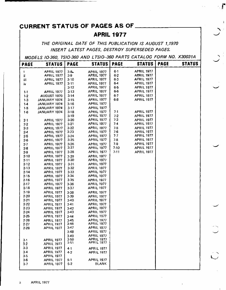
CURRENTSTATUSOFPAGESASOF APRIL 1977 THE ORIGINAL DA TE OF THIS PUBLICATION IS AUGUST 1,1970 INSERT LATEST PAGES, DESTROY SUPERSEDED PAGES. MODELS 10-360, TSIO-360 AND LTSIO--360 PARTS CATALOG FORM NO. X30031A PAGE STATUS APRIL 1977 APRIL 1977 APRIL 1977 APRIL 1977 APRIL 1977 AUGUST 1970 JANUARY 1974 JANUARY 1974 JANUARY 1974 JANUARY 1974 APRIL 1977 APRIL 1977 APRIL 1977 APRIL 1977 APRIL 1977 APRIL 1977 APRIL 1977 APRIL 1977 APRIL 1977 APRIL 1977 APRIL 1977 APRIL 1977 APRIL 1977 APRIL 1977 APRIL 1977 APRIL 1977 APRIL 1977 APRIL 1977 APRIL 1977 APRIL 1977 APRIL 1977 APRIL 1977 APRIL 1977 APRIL 1977 APRIL APR I L APRIL APRIL APRIL APRIL 1977 APRIL 1977 APRIL 1977 APRIL 1977 APRIL 1977 APRIL 1977 APRIL 1977 APRIL 1977 APRIL 1977 APRIL 1977 APRIL 1977 APRIL 1977 APRIL 1977 APRIL 1977 APRIL 1977 APRIL 1977 APRIL 1977 APRIL 1977 APRIL 1977 APRIL 1977 APRIL 1977 APRIL 1977 APRIL 1977 APRIL 1977 APRIL 1977 APRIL 1977 APRIL 1977 APRIL 1977 APRIL 1977 APRIL 1977 APRIL 1977 APRIL 1977 APRIL 1977 APRIL 1977 APRIL 1977 APRIL 1977 APRIL 1977 APRIL 1977 APRIL 1977 APRIL 1977 APRIL 1977 APRIL 1977 APRIL 1977 APRIL 1977 APRIL 1977 APRIL 1977 APRIL 1977 APRIL 1977 APRIL 1977 APRIL 1977 APRIL 1977 APRIL 1977 APRIL 1977 BLANK PAGE STATUS APRIL 1977 APRIL 1977 APRIL 1977 APRIL 1977 APRIL 1977 APRIL 1977 APRIL 1977 APRIL 1977 APRIL 1977 APRIL 1977 APRIL 1977 APRIL 1977 APRIL 1977 APRIL 1977 APRIL 1977 APRIL 1977 APRIL 1977 APRIL 1977 APRIL 1977 1 PAGE STATUS 1 PAGE STATUS 1 I I APRIL 1977
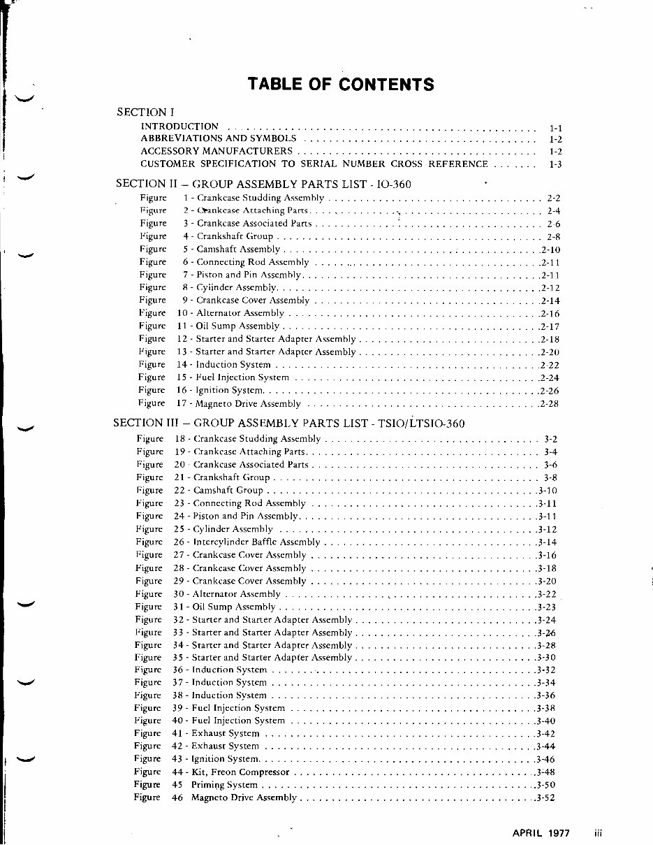
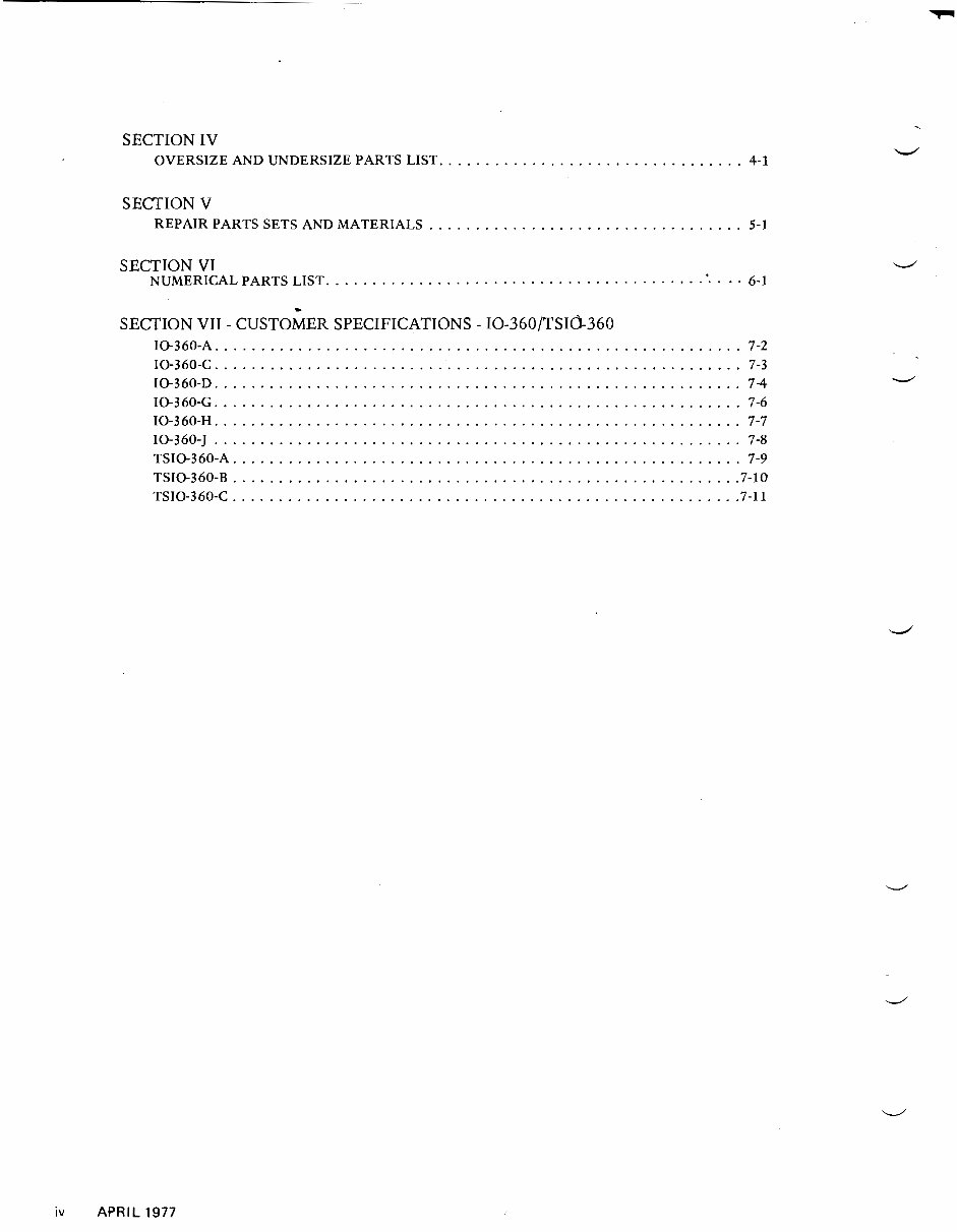
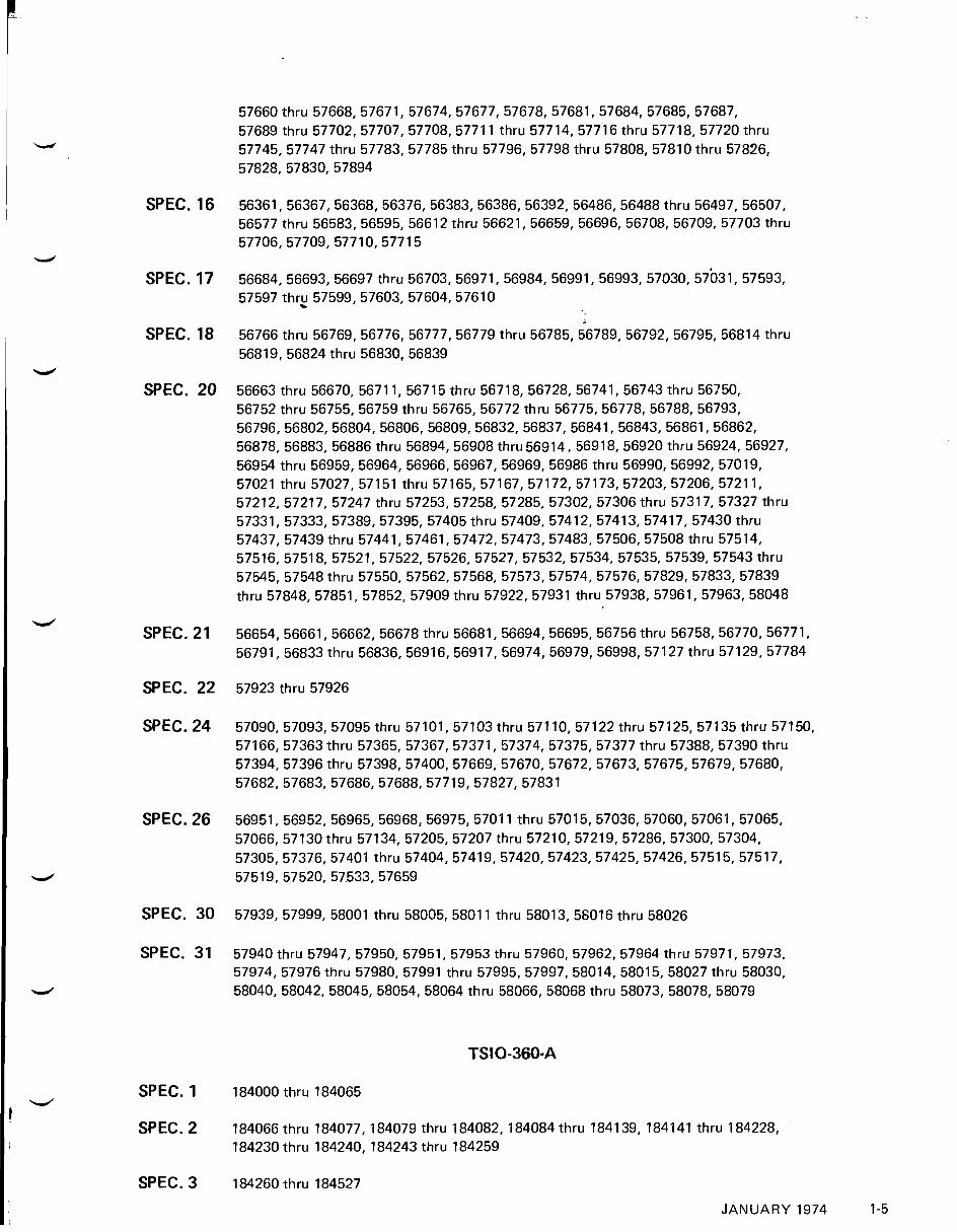
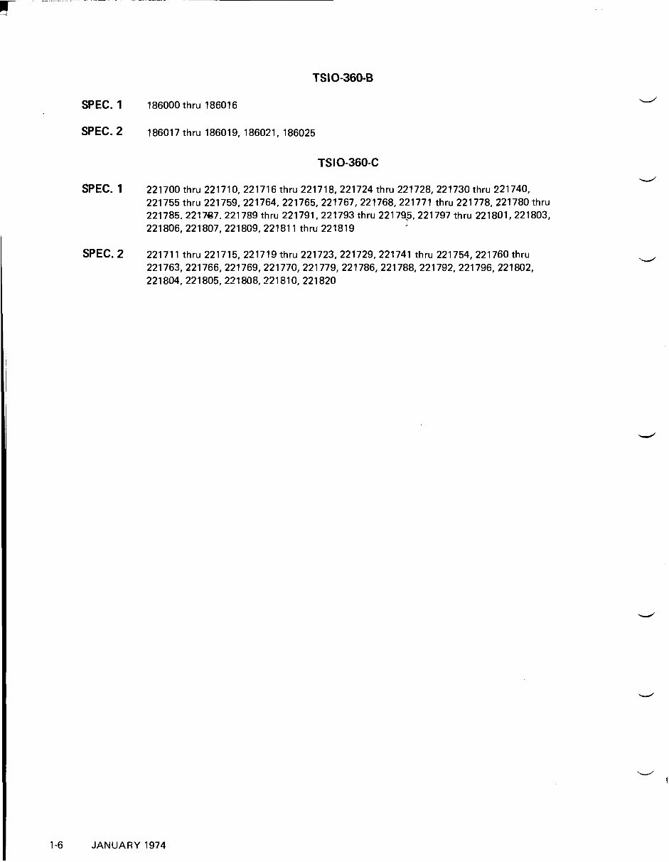
TABLE OF CONTENTS SECTION I INTRODUCTION ................................................ 1-1 ABBREVIATIONS AND SYMBOLS ..................................... 1-2 ACCESSORY MANUFACTURERS ...................................... 1-2 ....... CUSTOMER SPECIFICATION TO SERIAL NUMBER CROSS REFERENCE 1-3 SECTION I1 . GROUP ASSEMBLY PARTS LIST . 10-360 . .................................. Figure 1 Crankcase Studding Assembly 2-2 Figure 2 . Oankcase Attaching Parts ...................................... 2-4 Figure 3 . Crankcase Associated Parts ............. ...................... 2-6 Figure 4 . Crankshaft Group .......................................... 2-8 Figure 5 . Camshaft Assembly ......................................... 2.10 Figure 6 . Connecting Rod Assembly ..................................... 2.11 Figure 7 . Piston and Pin Assembly ...................................... 2.11 Figure 8 . Cylinder Assembly .......................................... 2.12 Figure 9 . Crankcase Cover Assembly .................................... 2.14 Figure 10 . Alternator Assembly ........................................ 2.16 Figure 11 . Oil Sump Assembly ......................................... 2.17 . Figure 12 Starter and Starter Adapter Assembly ............................. 2.18 Figure 13 . Starter and Starter Adapter Assembly ............................. 2.20 Figure 14 . Induction System .......................................... 2.22 Figure 15 . Fuel Injection System ....................................... 2.24 Figure 16 . Ignition System ............................................ 2.26 . Figure 17 Magneto Drive Assembly ..................................... 2.28 SECTION I11 . GROUP ASSEMBLY PARTS LIST . TSIO/LTSIO-360 Figure Figure Figure Figure Figure Figure Figure Figure Figure Figure Figure Figure Figure Figure Figure Figure Figure Figure Figure Figure Figure Figure Figure Figure Figure Figure Figure Figure Figure 18 . Crankcase Studding Assembly .................................. 3-2 19 . Crankcase Attaching Parts ..................................... 3-4 20 . Crankcase Associated Parts .................................... 3-6 21 . Crankshaft Group .......................................... 3-8 . 22 Camshaft Group ........................................... 3.10 23 . Connecting Rod Assembly .................................... 3.11 24 . Piston and Pin Assembly ...................................... 3.11 25 . Cylinder Assembly ......................................... 3.12 26 . Intercylinder Baffle Assembly .................................. 3.14 27 . Crankcase Cover Assembly .................................... 3.16 28 . Crankcase Cover Assembly .................................... 3.18 29 . Crankcase Cover Assembly .................................... 3.20 ....................... 30 . Alternator Assembly ................ 3.22 3 1 . Oil Sump Assembly ......................................... 3.23 32 . Starter and Starter Adapter Assembly ............................. 3.24 3 3 . Starter and Starter Adapter Assembly ............................. 3.w 34 . Starter and Starter Adapter Assembly ............................. 3.28 35 . Starter and Starter Adapter Assembly ............................. 3.30 36 . Induction System .......................................... 3.32 . 3 7 Induction System .......................................... 3.34 38 . Induction System .......................................... 3.36 39 . Fuel Injection System ....................................... 3.38 40 . Fuel Injection System ....................................... 3.40 41 . Exhaust System ........................................... 3.42 . 42 Exhaust System ........................................... 3.44 43 . Ignition System ............................................ 3.46 44 . Kit, Freon Compressor ...................................... 3.48 ............................................ 45 Priming System 3.50 46 Magneto Drive Assembly ..................................... 3.52 APRIL 1977 iii
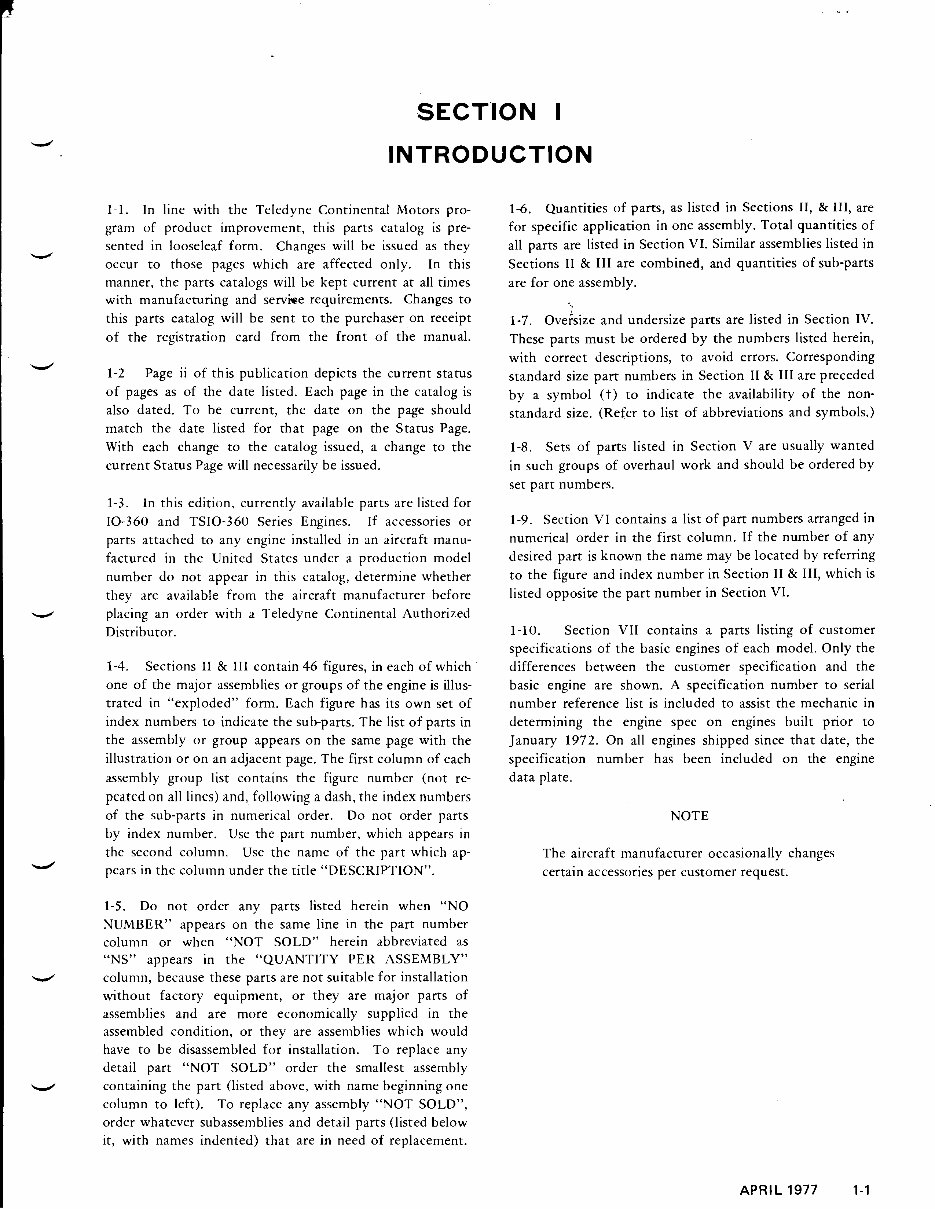
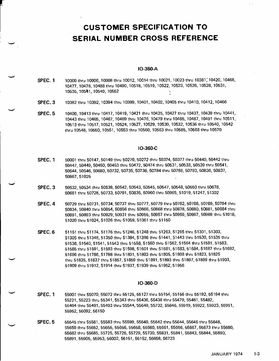
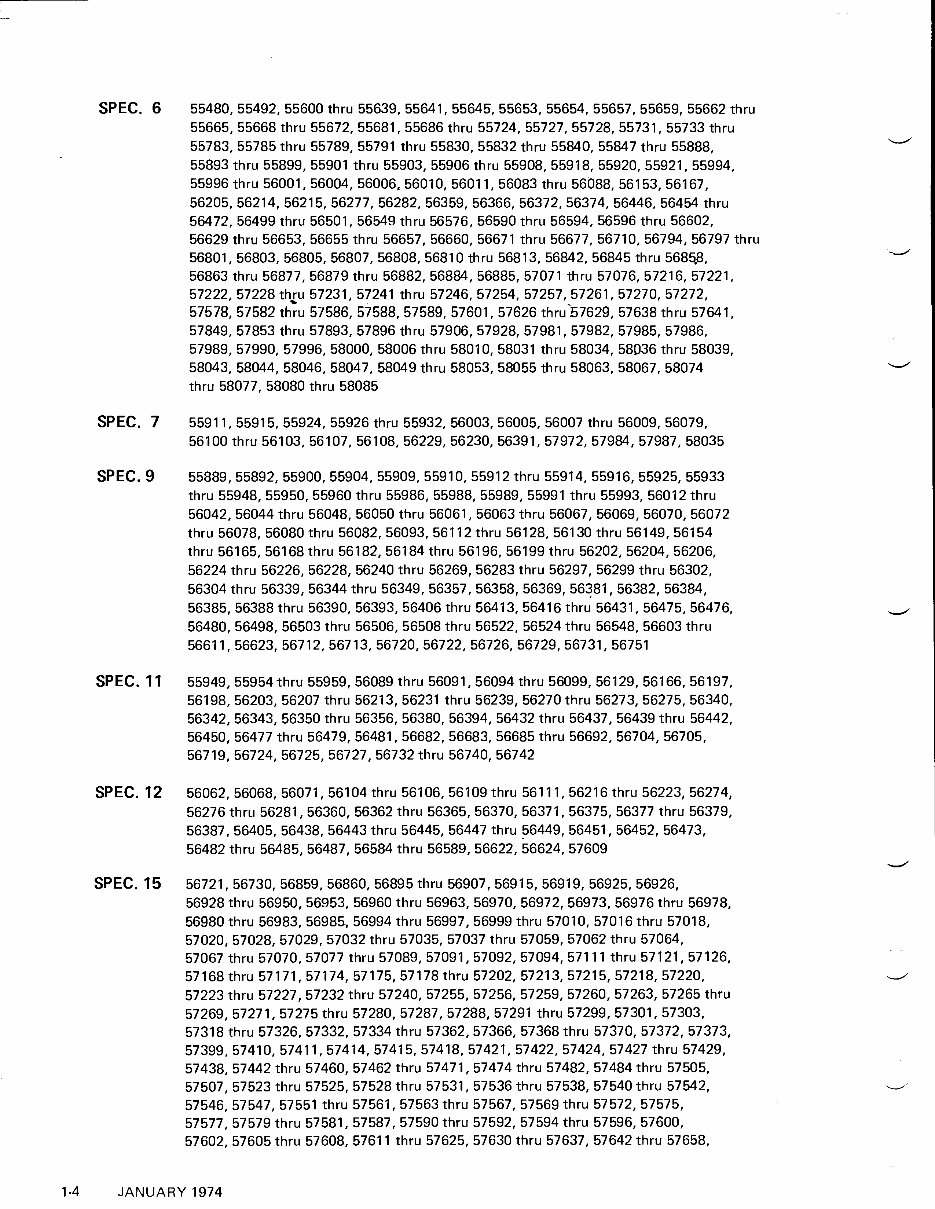
SECTION I INTRODUCTION 1-1. In line with the Teledyne Continental Motors pro- gram of product improvement, this parts catalog is pre- sented in looseleaf form. Changes will be issued as they e occur to those pages which are affected only. In this manner, the parts catalogs will be kept current at all times with manufacturing and servise requirements. Changes to this parts catalog will be sent to the purchaser on receipt of the registration card from the front of the manual. e 1-2 Page ii of this publication depicts the current status of pages as of the date listed. Each page in the catalog is also dated. To be current, the date on the page should match the date listed for that page on the Status Page. With each change to the catalog issued, a change to the current Status Page will necessarily be issued. 1-3. In this edition, currently available parts are listed for 10-360 and TSIO-360 Series Engines. If accessories or parts attached to any engine installed in an aircraft manu- factured in the United States under a production model number do not appear in this catalog, determine whether they are available from the aircraft manufacturer before d placing an order with a Teledyne Continental Authorized Distributor. 1-4. Sections I1 & 111 contain 46 figures, in each of which one of the major assemblies or groups of the engine is illus- trated in "exploded" form. Each figure has its own set of index numbers to indicate the sub-parts. The list of parts in the assembly or group appears on the same page with the illustration or on an adjacent page. The first column of each assembly group list contains the figure number (not re- peated on all lines) and, following a dash, the index numbers of the sub-parts in numerical order. Do not order parts by index number. Use the part number, which appears in the second column. Use the name of the part which ap- 4 pears in the column under the title "DESCRIPTION". 1-5. Do not order any parts listed herein when "NO NUMBER" appears on the same line in the part number column or when "NOT SOLD" herein abbreviated as "NS" appears in the "QUANTITY PER ASSEMBLY" 4 column, because these parts are not suitable for installation without factory equipment, or they are major parts of assemblies and are more economically supplied in the assembled condition, or they are assemblies which would have to be disassembled for installation. To replace any detail part "NOT SOLD" order the smallest assembly 1-6. Quantities of parts, as listed in Sections I 1 & 111, are for specific application in one assembly. Total quantities of all parts are listed in Section VI. Similar assemblies listed in Sections I1 & I11 are combined, and quantities of sub-parts are for one assembly. 1-7. oversize and undersize parts are listed in Section IV. These parts must be ordered by the numbers listed herein, with correct descriptions, to avoid errors. Corresponding standard size part numbers in Section I1 & I11 are preceded by a symbol (t) to indicate the availability of the non- standard size. (Refer to list of abbreviations and symbols.) 1-8. Sets of parts listed in Section V are usually wanted in such groups of overhaul work and should be ordered by set part numbers. 1-9. Section VI contains a list of part numbers arranged in numerical order in the first column. If the number of any desired part is known the name may be located by referring to the figure and index number in Section I1 & 111, which is listed opposite the part number in Section VI. 1-10. Section VII contains a parts listing of customer specifications of the basic engines of each model. Only the differences between the customer specification and the basic engine are shown. A specification number to serial number reference list is included to assist the mechanic in determining the engine spec on engines built prior to January 1972. On all engines shipped since that date, the specification number has been included on the engine data plate. NOTE The aircraft manufacturer occasionally changes certain accessories per customer request. u containing the part (listed above, with name beginning one column to left). To replace any assembly "NOT SOLD'', order whatever subassemblies and detail parts (listed below it, with names indented) that are in need of replacement.
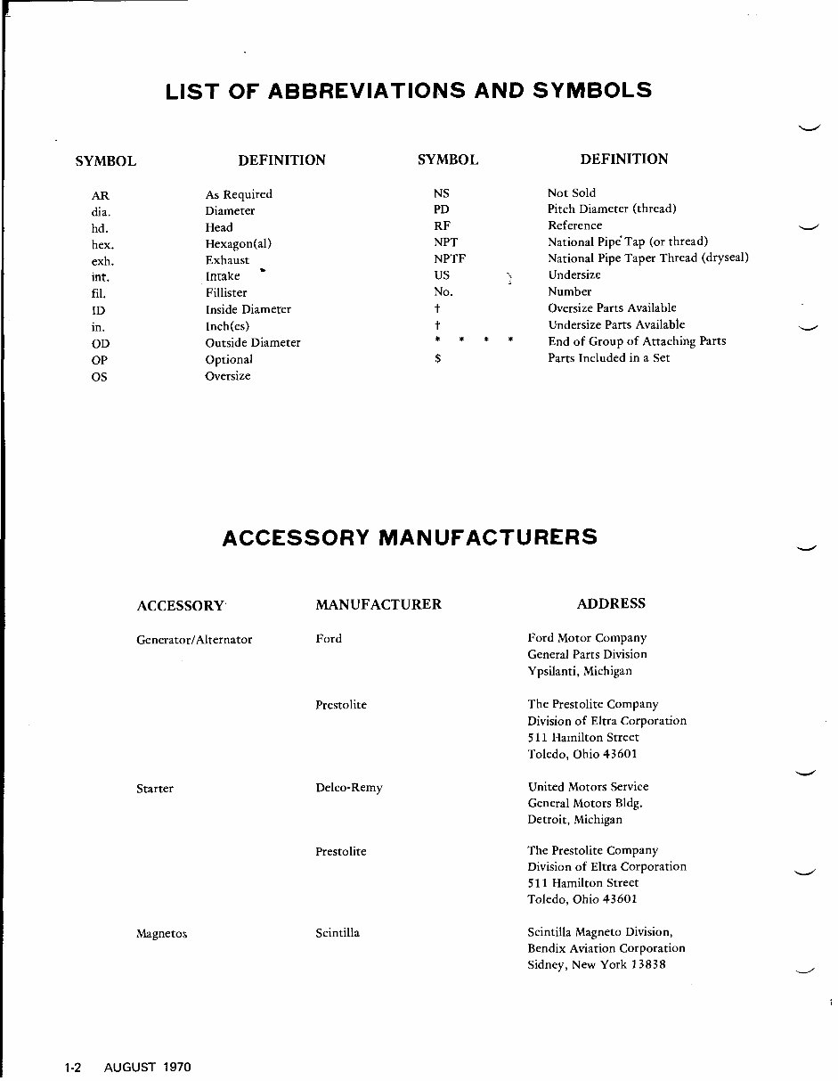
SYMBOL AR dia. hd . hex. exh. int. fil. ID in. OD OP 0s LIST OF ABBREVIATIONS AND SYMBOLS DEFINITION SYMBOL As Required Diameter Head Hexagon(a1) Exhaust Intake * Fillister Inside Diameter Inch(es) Outside Diameter Optional Oversize NS PD RF NPT NPTF us No. t t * * * * $ DEFINITION Not Sold Pitch Diameter (thread) Reference National Pipe Tap (or thread) National Pipe Taper Thread (dryseal) Undersize Number Oversize Parts Available Undersize Parts Available End of Group of Attaching Parts Parts Included in a Set ACCESSORY MANUFACTURERS ACCESSORY, MANUFACTURER ADDRESS GeneratorIAlternator Ford Ford Motor Company General Parts Division Ypsilanti, Michigan Starter Magnetos Prestolite Delco-Remy Prestolite Scintilla The Prestolite Company Division of Eltra Corporation 5 11 Hamilton Street Toledo, Ohio 43601 United Motors Service General Motors Bldg. Detroit, Michigan The Prestolite Company Division of Eltra Corporation 5 11 Hamilton Street Toledo. Ohio 43601 Scintilla Magneto Division, Bendix Aviation Corporation Sidney, New York 13838 1-2 AUGUST 1970
This Teledyne Continental Motors Parts Manual/Catalog contains Part Numbers & Illustrations for Models IO-360, TSIO-360 and LTSIO-360 Series Aircraft Engines. It is a comprehensive resource for both professional mechanics and DIY enthusiasts.
Language: English
Format: PDF
Compatibility: Win/Mac
The manual is fully bookmarked, searchable, and indexed, allowing for easy navigation and quick access to the exact service repair procedures. It includes detailed illustrations, exploded diagrams, drawings, and photos to guide you through every service repair procedure.
This manual can be viewed on any computer, and it also allows zooming and printing capabilities. It provides the convenience of printing only what is needed, reducing paper waste and saving resources.
For a wide range of Engine Manuals, please feel free to email us with any specific needs you may have.