This Page is Blank 1u.pa.-co.1 http://www.ioffer.com/selling/userfriendlycds http://stores.ebay.com/UserFriendlyCDs ii
CONTINENTAL A 50, A 6 5 , A 7 5 , A80 ENGINES INTRODUCTION THIS book is a combined Operator's Manual, Maintenance and Overhaul Manual and Illustrated Parts and Price List for the Continental A50, A65, A 75, and A80 series 8 and 9 engines. This manual is intended for use by operators and mechanics as a guide and reference book in the operation and servicing of these engines. The book is divided into five main groups: Operating and Maintenance Instructions, Overhaul Instructions, Table of Limits, the Illustrated Parts List, and Accessories. It is suggested that a careful study be made of this manual. A strict adherence to the instructions outlined herein will assure a fine operating record. However, if any point is not entirely clear, do not hesitate to contact the nearest Authorized Conti- nental Service Station or the factory Service Department. In the event of failure of any engine part, notify the nearest Authorized Continental Service Station at once, giving the engine serial number, and full particulars. Do not attempt any repairs without factory permission if any adjustment is expected. CONTINENTAL MOTORS CORPORATION Muskegon, Michigan iii
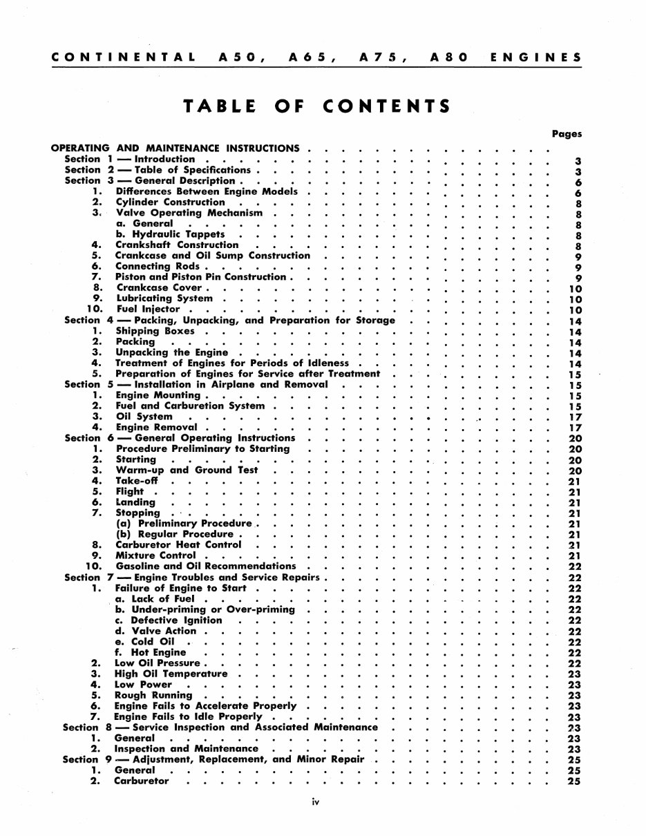
CONTINENTAL A 50, A 6 5 , A 7 5 , A80 TABLE OF CONTENTS OPERATING AND MAINTENANCE INSTRUCTIONS • Section 1 - Introduction Section 2 - Table of Specifications • Section 3 - General Description • 1 • Differences Between Engine Models • 2. Cylinder Construction 3, Valve Operating Mechanism • 4. 5. 6. 7. 8. 9. 10. a. General b. Hydraulic Tappets Crankshaft Construction Crankcase and Oil Sump Construction Connecting Rods • Piston and Piston Pin Construction • Crankcase Cover • Lubricating System • Fuel Injector • Section 1. 2. 3. 4. 5. 4 - Packing, Unpacking, and Preparation for Storage Shipping Boxes • Packing Unpacking the Engine • Treatment of Engines for Periods of Idleness • Preparation of Engines for Service after Treatment Section 1. 2. 3. 4. Section 1. 2. 3. 4. 5. 6. 7. 5 - Installation in Airplane and Removal Engine Mounting • Fuel and Carburetion System • Oil System Engine Removal . 6 - General Operating Instructions Procedure Preliminary to Starting Starting Warm-up and Ground Test Take-off Flight • Landing Stopping (a) Preliminary Procedure. (b) Regular Procedure. Carburetor Heat Control Mixture Control • 8. 9. 10. Gasoline and Oil Recommendations Section 7 - Engine Troubles and Service Repairs • 1 • Failure of Engine to Start • , a. Lack of Fuel • b. Under-priming or Over-priming c. Defective Ignition d. Valve Action • e. Cold Oil f. Hot Engine 2. Low Oil Pressure • 3. High Oil Temperature • 4. Low Power 5. Rough Running 6. Engine Fails to Accelerate Properly • '7. Engine Fails to Idle Properly • '. Section 8 - Service Inspection and Associated Maintenance 1. General 2. Inspection and Maintenance Sect'ion 9 - Adjustment, Replacement, and Minor Repair • 1. General 2. Carburetor iv .. ENGINES Pages 3 3 6 6 8 8 8 8 8 9 9 9 10 10 10 14 14 14 14 14 15 15 15 15 17 17 20 20 20 20 21 21 21 21 21 21 21 21 22 22 22 22 22 22 22 22 22 22 23 23 23 23 23 23 23 23 25 25 25
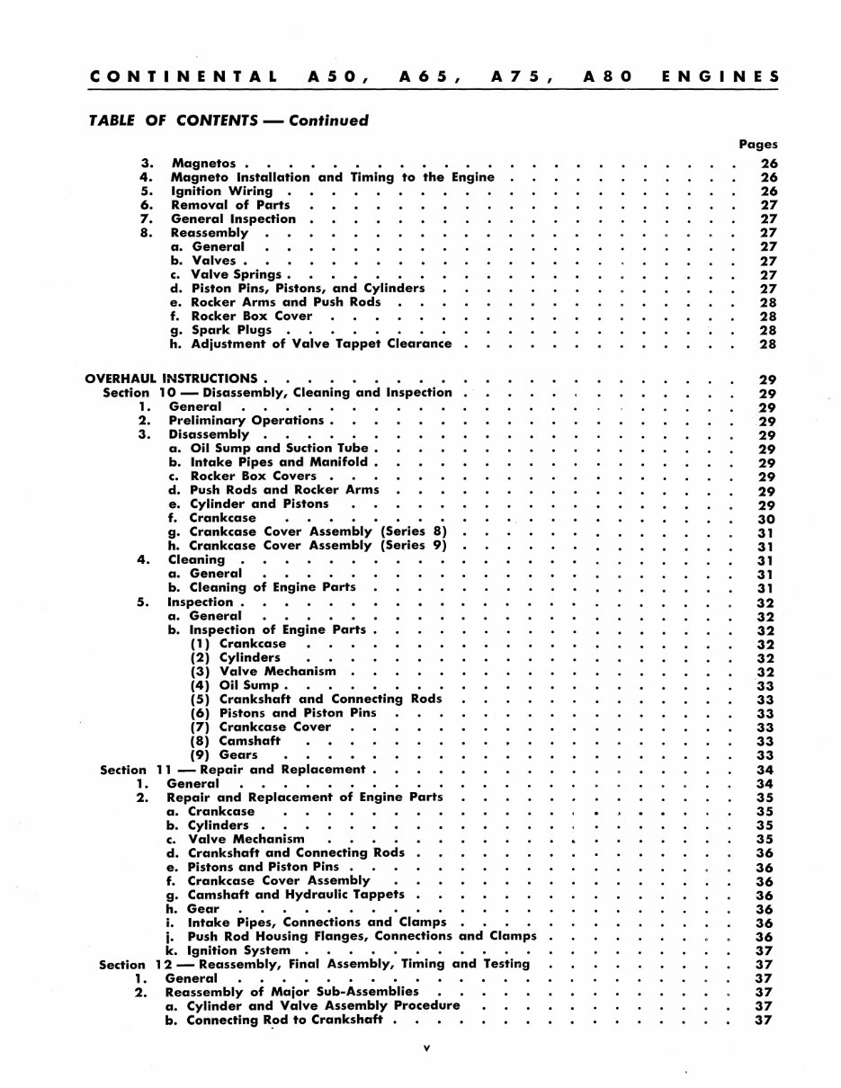
CONTINENTAL A 50, A 6 5 , A 7 5 , TABLE Of CONTENTS - Continued 3. Magnetos. 4. Magneto Installation and Timing to the Engine 5. Ignition Wiring • 6. Removal of Parts 7. General Inspection • 8. Reassembly a. General b. Valves. c. Valve Springs. d. Piston Pins, Pistons, and Cylinders e. Rocker Arms and Push Rods f. Rocker Box Cover g. Spark Plugs • h. Adjustment of Valve Tappet Clearance OVERHAUL INSTRUCTIONS • Section 1. 2. 3. 4. 5. Section 1. 2. Section 1. 2. 10 - Disassembly, Cleaning and Inspection General Preliminary Operations • Disassembly • a. Oil Sump and Suction Tube • b. Intake Pipes and Manifold • c. Rocker Box Covers • d. Push Rods and Rocker Arms e. Cylinder and Pistons f. Crankcase g. Crankcase Cover Assembly (Series 8) h. Crankcase Cover Assembly (Series 9) Cleaning a. General b. Cleaning of Engine Parts Inspection • a. General b. Inspection of Engine Parts (1) Crankcase (2) Cylinders (3) Valve Mechanism (4) Oil Sump. (5) Crankshaft and Connecting Rods (6) Pistons and Piston Pins (7) Crankcase Cover (8) Camshaft (9) Gears 11 - Repair and Replacement General • Repair and Replacement of Engine Parts a. Crankcase b. Cylinders • c. Valve Mechanism d. Crankshaft and Connecting Rods e. Pistons and Piston Pins • f. Crankcase Cover Assembly g. Camshaft and Hydraulic Tappets h. Gear • i. Intake Pipes, Connections and Clamps j. Push Rod Housing Flanges, Connections and Clamps k. Ignition System • 12 - Reassembly, Final Assembly, Timing and Testing General • • Reassembly of Major Sub-Assemblies a. Cylinder and Valve Assembly Procedure b. Connecting R~d to Crankshaft • v A80 ENGINES Pages 26 26 26 27 27 27 27 27 27 27 28 28 28 28 29 29 29 .29 29 29 29 29 29 29 30 31 31 31 31 31 32 32 32 32 32 32 33 33 33 33 33 33 34 34 35 35 35 35 36 36 36 36 36 36 36 37 37 37 37 37 37
CONTINENTAL A 50, A 6 5 , A 7 5 , TABLE Of CONTENTS - Continued c. Pistons and -Piston Pins • • d. Crankcase Cover Assembly (Series 8) e. Crankcase Cover Assembly (Series 9) f. Intake Pipes and Hose Connections • 3. Final Assembly Procedure • a. Preliminary b. Installing Crankshaft and Connection Rods • c. Assembly of Crankcases and Component Parts • d. Installing Gears and Crankcase Cover • e. Installing Oil Sump and Oil Suction Tube • f. Installing Hydraulic Units and Push Rod Housing Flanges. g. Installing Cylinders. • h. Installing Air Intake System • i. Installing Ignition System • j. Installing Radio Shielded Ignition Wires k. Testing Engine After Overhaul • TABLE OF LIMITS ILLUSTRATED PARTS LIST • Section 13 - Introduction • Section 14 - Group Assembly Parts List Section 1 5 - Numerical Parts List Section 16 - Oversize and Undersize Parts ACCESSORIES. • Section 1 7 - Stromberg NA-S3A 1 Carburetor Service Instructions Service Parts List • Section 1 8 - Bendix-Scintilla Magneto Service Instructions ' • Service Parts List • Section 1 9 - Wilcox Rich Hydraulic Lifters Service Instructions , . vi ., A80 ENGINES Pages 37 37 38 38 38 38 39 40 41 42 42 42 43 44 45 45 49 51 51 53 78 89 91 91 94 96 96 98 102 102
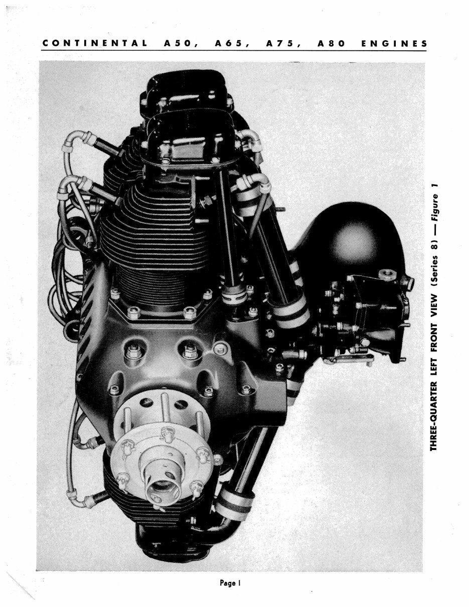
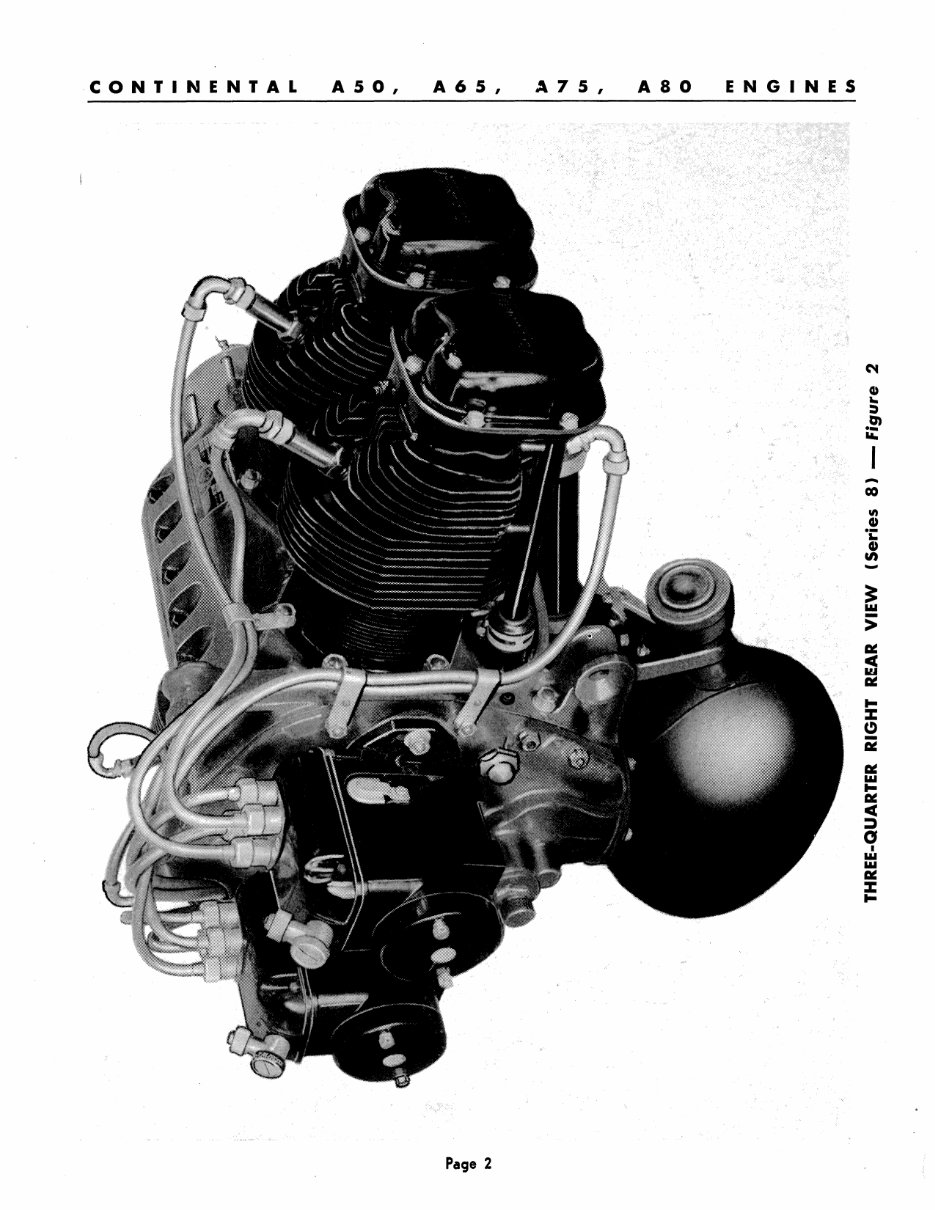
CONTINENTAL INDEX Figure No. A 5 0, FOR Title A 6 5 , A 7 5 , A80 ILLUSTRATIONS ENGINES Page No. 1 Three-Quarter Left Front View (Series 8) ................................... 1 2 Three-Quarter Right Rear View (Series 8) .................................. 2 3 Performance and Fuel Consumption Curves for A50, A65, A75, A80 Engines .. 5 4 Left Side View. . . . . . . . . . . . . . . . . . . . . . . . . . . . . . . . . . . . . . . . . . . . . . . . . . . . . . . . . . . . . . .. 7 5 Right Side View.............................................................. 7 6 Section Through Hydraulic Tappet. . . . . . . . . . . . . . . . . . . . . . . . . . . . . . . . . . . . . . . . . . .. 8 7 Fuel Injector Engine .......................................................... 11 8 Cutaway View Showing Gear Train .......................................... 13 9 Hoisting Engine with Crankshaft Lifting Eye ................................ 14 10 Hoisting Engine with Lifting Sling ........................................... 16 11 Typical Installation Diagram ................................................. 17 12 Installation Drawing .......................................................... 18 12a Installation Drawing .......................................................... 19 13 Ignition Wiring Diagram ..................................................... 26 14 Compressing· Valve Springs for Installation and Removal of Locks ........... 30 15 Removal of Hydraulic Unit from Cam Follower Body ......................... 30 16 Assembling and Removing Connecting Rods .................................. 31 17 Stud Identification ............................................................ 34 18 Assembling Rocker Shaft Bushings ........................................... 35 19 Installing Cam Follower Body into Crankcase ................................ 38 20 Installing -Crankshaft Bearings into Crankcase .............................. 39 21 Installing and Removing Crankshaft and Connecting Rods ................... 39 22 Installation of Crankcase 1-3 over Crankcase 2-4 ........................... .40 23 Installation of Gears in 'Crankcase ........................................... 41 24 Installation of Crankcase Cover to Crankcase .............. , ................. 41 25 Installation of Cylinder on Crankcase ........................................ 43 23 Determining Firing Position ................................................. 44 27 Lubrication Chart - Cross-sectional View .............................. , ..... 46 28 Lubrication Chart - Longitudinal View ...................................... 47 29 Lubrication Chart - Rear View ......................... : ................... 48 30 Crankcase - Illustrated Parts ·List ........................................... 52 31 Crankshaft, Connecting Rods and Pistons - Illustrated Parts List ............ 55 32 Cylinder and Valves - Illustrated Parts List ................................. 57 33 Rear Crankcase Cover and Gear Train - Illustrated Parts List .............. 59 34 Oil Sump and Suction Tube - Illustrated Parts List ......................... 62 35 Ignition System - Unshielded - Illustrated Parts List ....................... 64 36 Ignition System - Radio Shielded - Illustrated Parts List ................... 66 37 Carburetor, Carburetor Air Intake and Filter System - Illustrated Parts List. 68 38 Camshaft, Push Rods, Valve Tappets and Propeller Hub - Illustrated Parts List .................................................................. 70 39 Fuel Injector Equipment - Illustrated Parts List ............................ 72 40 Fuel Pump and Oil Cooler Equipment - Illustrated Parts List ................ 75 41 Showing Magneto Timing Markers ............................................ 96 42 Timing Magneto ............................................................. 96 43 Breaker Mechanism .......................................................... 97 44 Magneto Illustrated Parts ................................................... 100 vii
A.5 0 I A 6 5, A 7 5 , A80 ENG I N ES Page I - - co ; 0i: G) tn - ! > Ii- Z o ~ ... t: III ...
CONTINENTAL A 50, A 6 5 , .l 7 5 , A80 ENGINES .... Page 2
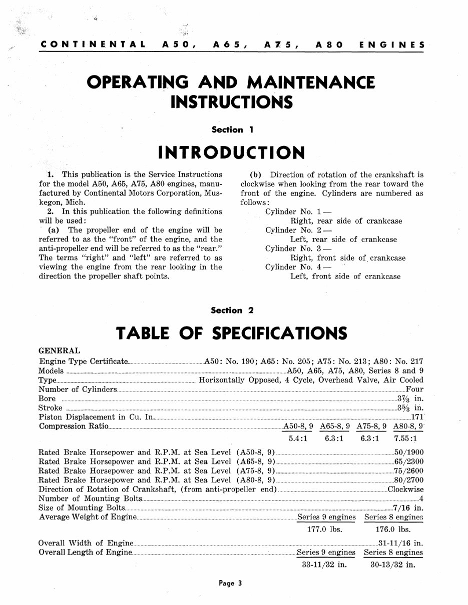
CONTINE.NTAL A 50, A 6 5 , A'Z 5 , A80 ENGINES OPERATING AND MAINTENANCE INSTRUCTIONS Section 1 INTRODUCTION 1. This publication is the Service Instructions for the model A50, A65, A 75, A80 engines, manu- factured by Continental Motors Corporation, Mus- kegon, Mich. 2. In this publication the following definitions will be used: (a) The propeller end of the engine will be referred to as the "front" of the engine, and the anti-propeller end will be referred to as the "rear." The terms "right" and "left" are referred to as viewing the engine from the rear looking in the direction the propeller shaft points. (b) Direction of rotation of the crankshaft is clockwise when looking from the rear toward the front of the engine. Cylinders are numbered as follows: Cylinder No. 1- Right, rear side of crankcase Cylinder No. 2- Left, rear side of crankcase Cylinder No. 3- Right, front side of crankcase Cylinder No. 4- Left, front side of crankcase Section 2 TABLE OF SPECIFICATIONS GENERAL Engine Type Certificate ..... _________ . __ . ________________________________ . __ A50 : No. 190; A65 : No. 205; A 75 : No. 213; A80 : No. 217 Models . __ ._. __ . ___ ............... ___ ...... ______ ... _ .. ______ . _______ ... ________ . _______ . _____ ........... __ . __ ._ .......... _._ .. ___ .A50, A65, A 75, A80, Series 8 and 9 Type ....................... _ .. ___ ..... _ .... __ .......... _______________________ . ______________ ...... Horizontally Opposed, 4 Cycle, Overhead Valve, Air Cooled Number of Cylinders __ .. ____________ .. ______ ... ___ .___________ _ ______________ . ____ ....... _. ________ ............. _._ ........ __ . _______ ....... _. ___ . ___ ........ __________________ .. ____ ...... Four Bore .. ____ ..... _ .. ___ .. ___ ... ___________ . __ . ______________________________________________ . _____________ .. ________ _ ____ . _________ .. ___ ... _. _____ . ________ .... __ . ___ ....... _. _____ . _____ . _________________ .. __________ ...... 3 0/8 in. Stroke .. _._ .. _____ . ____ .. _____ ........... _. ______ . __________ .______ _ ___________________ .... ___ . __________ ... _ .... __________ ....... _. _____ .. _. __ .... _____ . __ . _____________ . ___ ._----...... 30/8 in. Piston Displacement in Cu. In .... _______ _________ ......... _. ___ . ___ .___ _ ____________ .... ____. _____ .. __________ . ____ .. _____ ....... ___ ... ___ ._. ____ ... ____ . _____ ... __ ... _________ 171· Compression Ratio .......... _____ ... _____ ..... _____ ... ___ . __ . __ . ___ .. ____ .. ___ .. __ ._. __ ..... ___ ...... __ . ______ ._ .. _____ .. ___ . ____ A50-8, 9 A65-8,9 A75-8,9 A80-8,9' 5.4 :1 6.3:1 6.3:1 7.55:1 Rated Brake Horsepower and R.P.M. at Sea Level (A50-8, 9) ______ ... _ .. _. __ . __ ... _ .... _. __ .. _ .... _. __ .___. ____ . _____ 50/1900 Rated Brake Horsepower and R.P .M. at Sea Level (A65-8, 9) ... __________________ ... _____ . ________ . _________ ..... _. ___________ . _________________ 65 /2300 Rated Brake Horsepower and R.P.M. at Sea Level (A75-8, 9) ............ ________ .. _ ... ____ . _____ ............... __ ... ___ ........ _____ ..... _______ 75/2600 Rated Brake Horsepower and R.P .M. at Sea Level (A80-8, 9) . ___________ . __ . __ .. ______ ..... _________________ ....... _________________ . __________ .80 /2700 Direction of Rotation of Crankshaft, (from anti-propeller end) __ .. ________ .. ____ ......... __ .... _ ... _____ .. _. ______ .... _ .......... __ ......... Clockwise Number of Mounting Bolts ....... ___________ ........ ___ .. _ .. _ ............. _ ...... _____ ... _ .. _ ... _ .. ______ .... _ .. ____ .. ____________ ... ______________ . ___________ .. _ ...... ___ . ___________ . _________________ ._. ____ ... __ 4 Size of Mounting Bolts________ _ ________________________________ .. _________ . ___ .... ______________________ . _____ ... __ . ______________ . ___ . ___________ ........ ____ . ____ ..... __ . __ ._.7 /16 in. Average Weight of Engine ___ ... ____________ . ________ . ___________ ._. __ . ___ . ___ ........ _._____. ___________ .. _______Series 9 engines Series 8 engines 177.0 lbs. 176.0 lbs. Overall Width of Engine __ .... _____ .. __ . __ .. ____ . ___________ . _______ .. __ ..... _. ___________ .. _______________ . ______ ._....... ______ . _______ ................ __ .. _______ .. _. __ . _____ 31-11 /16 in. Overall Length of Engine .... _. ______ .... ______ ........ _____ .. _ ....... __ .. ______ .. _ .. ____________________ ..... ____ ..... _______ ._. __ Series 9 engines Series 8 engines 33-11/32 in. 30-13/32 in. Page 3
This manual is a comprehensive guide for the Continental A-50, A-65, A-75, and A-80 Series Engines, combining the Operator's Manual, Maintenance, Overhaul Manual, and Illustrated Parts and Price List.
It is designed with improved features such as bookmarks, searchable text, index, and enhanced quality for instant access without any waiting time.
The manual is available in English language and compatible with all versions of Windows, Mac, iOS, BB, Android, etc. It is searchable, bookmarked, and indexed for quick and easy navigation.
Intended for use by operators and mechanics, this manual serves as a clear and user-friendly reference for the operation and servicing of these engines.
With its bookmarked and searchable features, users can quickly find the information they need by simply clicking on the bookmark or typing in the search query.
It eliminates the need to spend a large sum on printed copies, allowing users to print specific sections as and when required, all in easy-to-read files.
Whether for home, repair shop, or business use, this manual serves as an excellent reference source, promoting cost-effective and environmentally friendly practices.
For immediate access to these manuals, simply click the "Buy Now" button.
Additional Information: Some documents may require the latest version of Acrobat Reader for optimal display. If you encounter any issues, consider upgrading to the newest version of Adobe Acrobat Reader.
For specific service manual inquiries, feel free to reach out via email.
Recently Viewed
5,521,897Happy Clients
2,594,462eManuals
1,120,453Trusted Sellers
15Years in Business
Price:
Actual Price:
Continental A50 A65 A75 A80 Owner Operator's Overhaul Service Manual Parts Manuals - IMPROVED -