

Chrysler Hemi 6 215, 245 & 265 Engine Overhaul Manual
What's Included?
Fast Download Speeds
Online & Offline Access
Access PDF Contents & Bookmarks
Full Search Facility
Print one or all pages of your manual

7-0- 1
GROUP 7 - COOLING SYSTEM
SECTION 0 - INDEX
Section Page
Subject Number Number
INDEX 0
SERVICE DIAGNOSIS
RADIATORS, PRESSURE CAPS, HOSES AND BELTS 2
Specifications 1
General Information 2
Radiator 2
Pressure Testing the Cooling System 2
Pressure Flushing the Cooling System 2
Radiator Cap 3
Radiator Hoses 3
Coolant Recovery System 4
Drive Belt Tensioning 4
WATER PUMPS, THERMOSTATS, FANS AND
SHROUD 3
Specifications 1
Water Pump ("D" type engine) 2
Water Pump ("LA" type engine) 3
Thermostat 4
Fan 5
Thermal Control Fan Drive 5
Thermal Ignition Control (T.I.C.) Valve
6
SERVICE BULLETIN REFERENCE
DATE NUMBER SUBJECT CHANGES
I
I

Condition
EXTERNAL
LEAKAGE
INTERNAL
LEAKAGE
POOR CIRCULATION
7- 1 - 1
SECTION 1 - SERVICE DIAGNOSIS
Possible Cause
(a) Loose hose clamp.
(b) Hose leaking.
(c) Leaking radiator.
(d) Worn or damaged water pump seal.
(e) Loose core hole plug.
(f) Damaged gasket, or dry gasket, if
engine has been stored.
(g) Cylinder head bolts loose, or
tightened unevenly.
(h) Leak at heater connection.
(i) Leak at water temperature sending
unit.
(j) Leak at water pump attaching bolts.
(k) Leak at exhaust manifold stud.
(I) Crushed thermostat housing.
(m) Dented radiator inlet or outlet tube.
Correction
(a) Replace the hose clamp.
(b) Replace the hose.
(c) Repair or replace the radiator as
necessary.
(d) Replace the water pump seal
and impeller.
(e) Install new core hole plug.
(f) Replace gaskets as necessary.
(g) Replace the cylinder head gasket and
torque head in correct sequence.
(h) Clean the heater connections and
replace the hoses and clamps if necessary.
(i) Tighten the water temperature
sending unit.
(j) Tighten the water pump attaching
bolts to specifications.
(k) Seal and re-drive the stud.
(I) Replace the thermostat housing.
(m) Straighten the radiator inlet or outlet
tube as necessary.
(n) Leaking heater core. (n) Repair or replace the heater core.
(o) Cracked or porous water pump housing. (o) Replace the water pump assembly.
(p) Warped or cracked cylinder head. (p) Replace the cylinder head.
(q) Cracked cylinder block. (q) Replace the cylinder block.
(r) Sand holes or porous condition in (r) Replace the cylinder block or
block or head. cylinder head as necessary.
(a) Faulty head gasket.
(b) Refer to causes (f) to (j) listed
under External Leakage.
(c) Cylinder head cracked into valve
compartment.
(d) Cracked valve port.
(e) Cylinder block cracked into push
rod compartment.
(f) Cracked cylinder wall.
(a) Low coolant level.
(b) Collapsed radiator hose. (A bottom
hose with faulty spring may collapse
only at high engine speeds).
(c) Fan belt glazed, oil soaked, or loose.
(d) Air leak through loose or faulty
bottom hose.
(e) Faulty thermostat.
(f) Water pump impeller broken or
loose on shaft.
(a) Install a new head gasket.
(b) Refer to corrections (f) to (j) listed
under External Leakage.
(c) Pressure test cooling system, replace
the cylinder head.
(d) Pressure test cooling system, replace
the cylinder head.
(e) Pressure test cooling system, replace
the cylinder block.
(f) Pressure test cooling system, replace
the cylinder block.
(a) Fill radiator to correct level.
(b) Replace the hose and spring as
necessary.
(c) Tighten or replace the fan belt as
necessary.
(d) Replace the hose.
(e) Replace the thermostat.
(0 Replace the water pump internal
parts.
Condition
OVERHEATING OR
APPARENT
OVERHEATING
(Refer to Causes Listed
under "Poor Circulation")
OVER FLOW LOSS
CORROSION
TEMPERATURE TOO
LOW - SLOW
ENGINE WARM UP
WATER PUMP NOISY
INSUFFICIENT
ACCESSORY OUTPUT
DUE TO BELT
SLIPPAGE
BELT SQUEAL WHEN
ACCELERATING
ENGINE
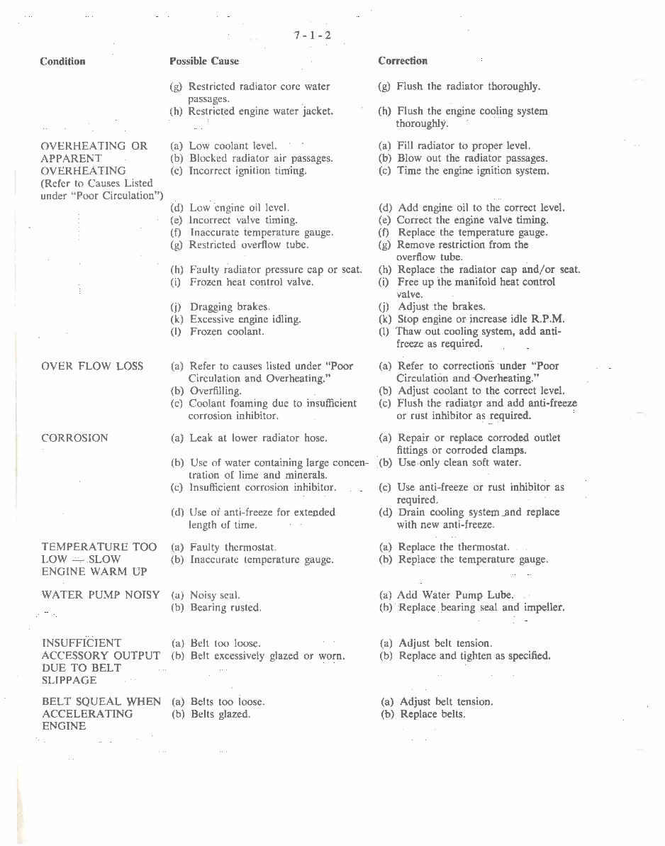
7- 1-2
Possible Cause
(g) Restricted radiator core water
passages.
(h) Restricted engine water jacket.
(a) Low coolant level.
(b) Blocked radiator air passages.
(c) Incorrect ignition timing.
(d) Low engine oil level.
(e) Incorrect valve timing.
(f) Inaccurate temperature gauge.
(g) Restricted overflow tube.
{h) Faulty radiator pressure cap or seat.
(i) Frozen heat control valve.
(j) Dragging brakes.
(k) Excessive engine idling.
(I) Frozen coolant.
(a) Refer to causes listed under "Poor
Circulation and Overheating."
(b) Overfilling.
(c) Coolant foaming due to insufficient
corrosion inhibitor.
(a) Leak at lower radiator hose.
Correction
(g) Flush the radiator thoroughly.
(h) Flush the engine cooling system
thoroughly.
(a) Fill radiator to proper level.
(b) Blow out the radiator passages.
(c) Time the engine ignition system.
(d) Add engine oil to the correct level.
(e) Correct the engine valve timing.
(f) Replace the temperature gauge.
(g) Remove restriction from the
overflow tube.
(h) Replace the radiator cap and/ or seat.
(i) Free up the manifold heat control
valve.
(j) Adjust the brakes.
(k) Stop engine or increase idle R.P.M.
(I) Thaw out cooling system, add anti-
freeze as required.
(a) Refer to corrections under "Poor
Circulation and Overheating."
(b) Adjust coolant to the correct level.
(c) Flush the radiator and add anti-freeze
or rust inhibitor as required.
(a) Repair or replace corroded outlet
fittings or corroded clamps.
(b) Use of water containing large concen- (b) Use only clean soft water.
tration of lime and minerals.
(c) Insufficient corrosion inhibitor.
(d) Use of anti-freeze for extended
length of time.
(a) Faulty thermostat.
(b) Inaccurate temperature gauge.
(a) Noisy seal.
(b) Bearing rusted.
(a) Belt too loose.
(b) Belt excessive ly glazed or worn.
(a) Belts too loose.
(b) Belts glazed.
(c) Use anti-freeze or rust inhibitor as
required.
(d) Drain cooling system and replace
with new anti-freeze.
(a) Replace the thermostat.
(b) Replace the temperature gauge.
(a) Add Water Pump Lube.
(b) Replace bearing seal and impeller.
(a) Adjust belt tension.
(b) Replace and tighten as specified.
(a) Adjust belt tension.
(b) Replace belts.
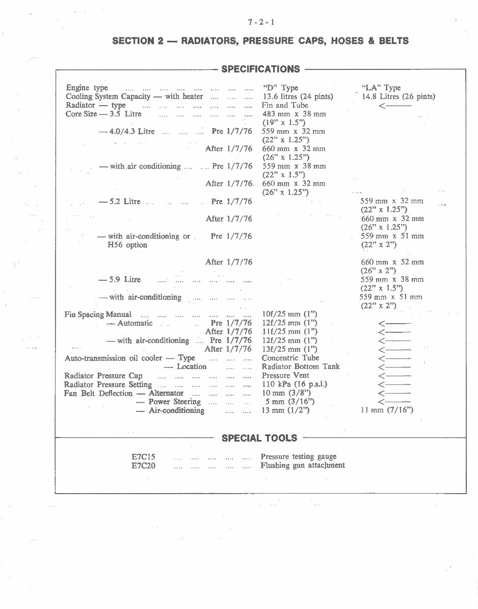
7-2-1
SECTION 2 - RADIATORS, PRESSURE CAPS, HOSES & BELTS
...---------------SPECIFICATIONS --------------,
Engine type .... 0 0. . .... .... 0 .. 0
Cooling System Capacity - with heater
Radiator - type
Core Size- 3o5 Litre
- 4o0/4o3 Litre Pre 1/7/76
After 1/7/76
. -with air conditioning ... . . .. Pre 1/7/76
-502 Litre . 0 . .. .. oo ..
- with air-conditioning or .
H56 option
- 5o9 Litre
- with air-conditioning
Fin Spacing Manual . . ... 0 0 .. .
After 1 /7/7 6
Pre 1/ 7/76
After 1/7/7 6
Pre 1/ 7/76
After 1/7/ 76
-Automatic . .. .. Pre 1/7/76
After 1/7/76
-with air-conditioning .... Pre 1/7 !76
After 1/7/7 6
Auto-transmission oil cooler - Type
-Location
Radiator Pressure Cap 000 0 •ooo .o ..
Radiator Pressure Setting .... 0 .. 0 .... . .. .
Fan Belt Deflection - Alternator 0... . .. 0
- Power Steering ....
- Air-conditioning
"D" Type
1306 litres (24 pints)
Fin and Tube
483 mm x 38 mm
(19" X 1.5'')
559 mm x 32 mm
(22" X 1.25")
660mm x 32mm
(26" X 1.25")
559 mm x 38 mm
(22" X lo5")
. 660mm x 32mm
(26" X 1.25")
lOf/25 mm (1 ")
12f/25 mm (1 ")
11£/2 5 mm (1 ")
12f/25 mm (1 ")
13f/ 25 mm (1 ")
Concentric Tube
Radiator Bottom Tank
Pressure Vent
110 kPa (16 pos.io)
10 mm (3/8")
Smm (3/16")
13 mm (1/2")
SPECIAL TOOLS
E7C15
E7C20
Pressure testing gauge
Flushing gun attachment
"LA" Type
1408 Litres (26 pints)
<---
559 mm x 32 mm
(22" X 1.25")
660mm x 32mm
(26" X lo25")
559 mm x 51 mm
(22" X 2")
660mm x 52mm
(26" X 2")
559 mm x 38 mm
(22" X 1.5")
559mm x 51 mm
(22" X 2")
<--
<- --
<-- -
<---
<---
<---
<---
<---
<---
<- --
11 mm (7 I 16")
7-2-2
GENERAL INFORMATION
All engines are equipped with a thermostat as stan-
dard equipment. With this thermostat, an ethyl-glycol
base type anti-freeze may be used. In order to maintain
cleanliness, the cooling system should be drained,
thoroughly rinsed and filled with the correct coolant in
accordance with the lubrication and maintenance
schedule.
Always discard old solutions removed. Maximum
cleanliness can be assured by using a cooling system
cleaner according to the directions on the label. If the
system is badly rusted or clogged, it should be pressure
flushed.
When draining the cooling system, the block drain
plugs should be removed and the radiator drain cock
opened. Refill with demineralised water (or clean rain-
water) adding Chrysler Parts Corrosion Inhibitor, also
a compatible anti-freeze where required.
The quantity of anti-freeze (if required) to be added
should be sufficient to protect at the lowest anticipated
temperature.
RADIATOR
Removal
(I) Drain cooling system.
(2) On vehicles with automatic transm1Ss1on, dis-
connect oil cooler lines at radiator bottom tank.
(3) Remove upper and lower radiator hoses (using
pliers E 1119).
(4) Where equipped remove shroud attaching screws,
separate shroud from radiator, position shroud rear-
ward on engine for maximum clearance.
(5) Remove radiator attaching screws.
( 6) Radiator can now be lifted free from engine
compartment. Care should be taken not to damage
radiator cooling fins or water tubes during removal.
Fan damage should always be avoided.
Installation
(I) Slide radiator down into position behind radia-
tor support and install attaching screws.
(2) Install fan shroud (if so equipped), connect
hoses, and connect transmission oil cooler lines, if so
equipped.
(3) Fill cooling system to 25 mm (1 ") below filler
neck seat with water and corrosion inhibitor as re-
quired. After warm-up, re-check coolant level. Main-
tain at 25 mm (I") below filler neck.
(4) On vehicles with automatic transmission measure
transmission oil level after warm up and add oil as
required.
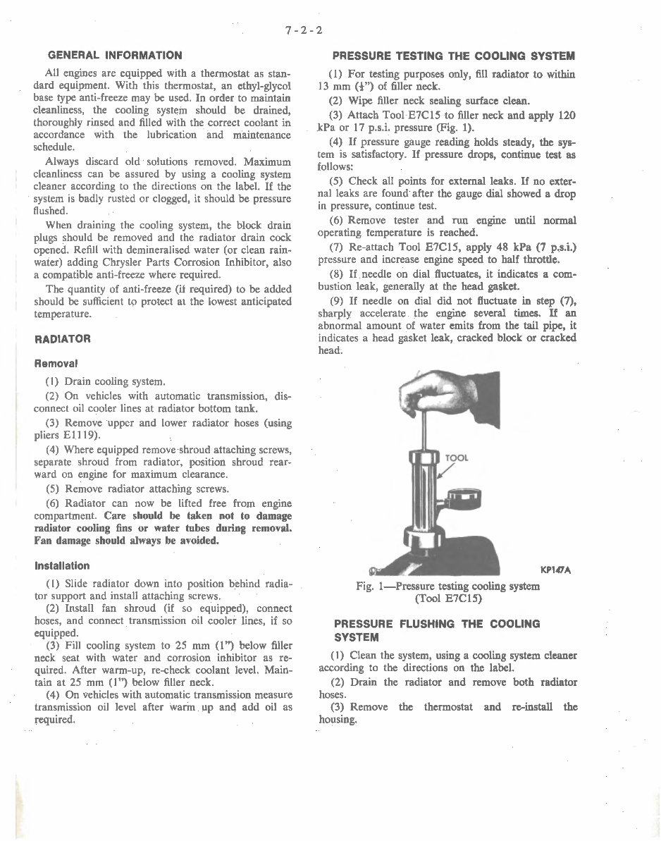
PRESSURE TESTING THE COOLING SYSTEM
( 1) For testing purposes only, fill radiator to within
13 mm (t") of filler neck.
(2) Wipe filler neck sealing surface clean.
(3) Attach Tool E7Cl5 to filler neck and apply 120
kPa or 17 p.s.i. pressure (Fig. 1).
(4) If pressure gauge reading holds steady, the sys-
tem is satisfactory. If pressure drops, continue test as
follows:
(5) Check all points for external leaks. If no exter-
nal leaks are found after the gauge dial showed a drop
in pressure, continue test.
(6) Remove tester and run engine until normal
operating temperature is reached.
(7) Re-attach Tool E7C15, apply 48 kPa (7 p,s.i.)
pressure and increase engine speed to half throttle.
(8) If needle on dial fluctuates, it indicates a com-
bustion leak, generally at the head gasket.
(9) If needle on dial did not fluctuate in step (7),
sharply accelerate the engine several times. If an
abnormal amount of water emits from the tail pipe, it
indicates a head gasket leak, cracked block or cracked
head.
Fig. !-Pressure testing cooling system
(Tool E7Cl5)
PRESSURE FLUSHING THE COOLING
SYSTEM
KPl.OA
(I) Clean the system, using a cooling system cleaner
according to the directions on the label.
(2) Drain the radiator and remove both radiator
hoses.
(3) Remove the thermostat and re-install the
housing.

7-2-3
(4) Connect flushing gun, Tool E7C20, to the engine
thermostat housing, using a length of rubber hose.
(5) Install a drain hose in the water pump inlet.
(6) Connect a flushing gun to sources of water and
air pressure.
(7) Fill the block with water by restricting the drain
hose. Leave the water valve open.
(8) Open and close the air valve to agitate and force
away any foreign material. Continue the operation until
the water runs clear.
(9) For final block flushing, fill the block with water
and remove the drain plugs. Using air pressure until
the water from the block drains runs clear.
(10) To pressure flush the radiator, disconnect the
two hoses from the engine and attach them to the
radiator. Attach the flushing gun hose to the lower
radiator tank and the drain hose to the top tank.
(11) Fill the radiator with water, leave the water
valve open, and open and close the air valve until the
water runs clear.
(12) For final radiator flushing, attach flushing gun
to top hose and repeat flushing operation.
(13) Test the thermostat (see Section 3). If satis-
factory, install with pellet toward engine, using a new
gasket.
(14) Install hoses and refill cooling system to 25 mm
( 1 ") below filler neck, using demineralised (or rain)
water and adding Chrysler Parts Corrosion Inhibitor
also a compatible anti-freeze, where required.
(15) Run engine until the temperature gauge indi-
cates normal operating temperature and continue an
additional five minutes to release any air trapped in
system. Check coolant level and, if necessary, add addi-
tional water.
RADIATOR CAP
This cap is the pressure-sealing type. Its putpose is
to hold .the cooling system under a slight pressure, in-
creasing the boiling point of the cooling solution and
preventing loss of solution due to evaporation and over-
Fig. 2-Radiator pressure caps
The cap (Fig. 2) has spring-loaded valve, the seat of
which is below the overflow pipe in the filler neck. This
prevents the escape of air or liquid while the cap is in
position. When the cooling system pressure reaches a
pre-determined point, the cap valve opens and will
again close when the pressure drops below the pre-
determined point.
When removing the pressure type cap from the
radiator, perform the operation in two steps. Loosening
the cap to its first notch raises the valve from the gasket
and releases the pressure through overflow pipe. In the
first stage position of the cap it should be possible to
depress the cap approximately 3mm (1/8").
The prongs on the cap can be bent to adjust this
condition. Care must be taken that the cap is not too
loose as this would prevent proper sealing.
CAUTION: When removing the cap, loosen it
slowly and then pause a moment. This will
avoid possible burning by hot water or
steam. Continue to turn the cap to the left
until it can be removed.
Fig. 3- Testing the pressure cap (Tool E7Cl5)
Pressure Testing the Radiator Cap
(1) Attach neoprene seal and adaptor to tester
E7C15 (See Fig. 3).
(2) Dip the pressure cap in water and apply cap to
tester adaptor.
(3) Apply pressure to cap. If pressure cap fails to
hold pressure up to the specified pressure of the cap,
replace the cap.
RADIATOR HOSES
The hoses are removed and installed using hose
clamp pliers E1119. A hardened, cracked, or swollen
hose should be replaced.
The spring inside the lower hose is necessary to pre-
vent collapsing of the hose due to suction at high engine
speeds.
If this spring is weak or broken, it should be
replaced.
7-2-4
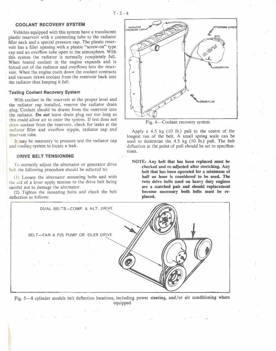
COOLANT RECOVERY SYSTEM
Vehicles equipped with this system have a translucent
plastic reservoir with a connecting tube to the radiator
filler neck and a special pressure cap. The plastic reser-
voir has a filler opening with a plastic "screw-on" type
cap and an overflow tube open to the atmosphere. With
this system the radiator is normally completely full.
When heated coolant in the engine expands and is
forced out of the radiator and overflows into the reser-
voir. When the engine cools down the coolant contracts
and vacuum draws coolant from the reservoir back into
the radiator thus keeping it full.
Testing Coolant Recovery System
With coolant in the reservoir at the proper level and
the radiator cap installed, remove the radiator drain
plug. · coolant should be drawn from the reservoir into
the radiator. Do not leave drain plug out too long as
this could allow air to enter the system. If test does not
draw coolant from the reservoir, check for leaks at the
radiator filler and overflow nipple, radiator cap and
reservoir tube.
It may be necessary to pressure test the radiator cap
and cooling system to locate a leak.
DRIVE BELT TENSIONING
To correctly adjust the alternator or generator drive
belt the following procedure should be adhered to:
(I) Loosen the alternator mounting bolts and with
the aid of a lever apply tension to the drive belt being
careful not to damage the alternator.
(2) Tighten the mounting bolts and check the belt
deflection as follows:
DUAL BEL TS-COMP . & ALT. DRIVE
BELT- FAN & P/S PUMP OR IDLER DRIVE
Fig. 4- Coolant recovery system
Apply a 4.5 kg (10 lb.) pull to the centre of the
longest run of the belt. A small spring scale can be
used to determine the 4.5 kg (I 0 lb.) pull. The belt
deflection at the point of pull should be set to specifica-
tions.
NOTE: Any belt that bas been replaced must be
checked and re-adjusted after stretching. Any
belt that bas been operated for a minimum of
half an hour is considered to be used. The
twin drive belts used on heavy duty engines
are a matched pair and should replacement
become necessary both belts must be re-
placed.
Fig. 5-8 cylinder models belt deflection locations, including power steering, and/or air conditioning where
equipped
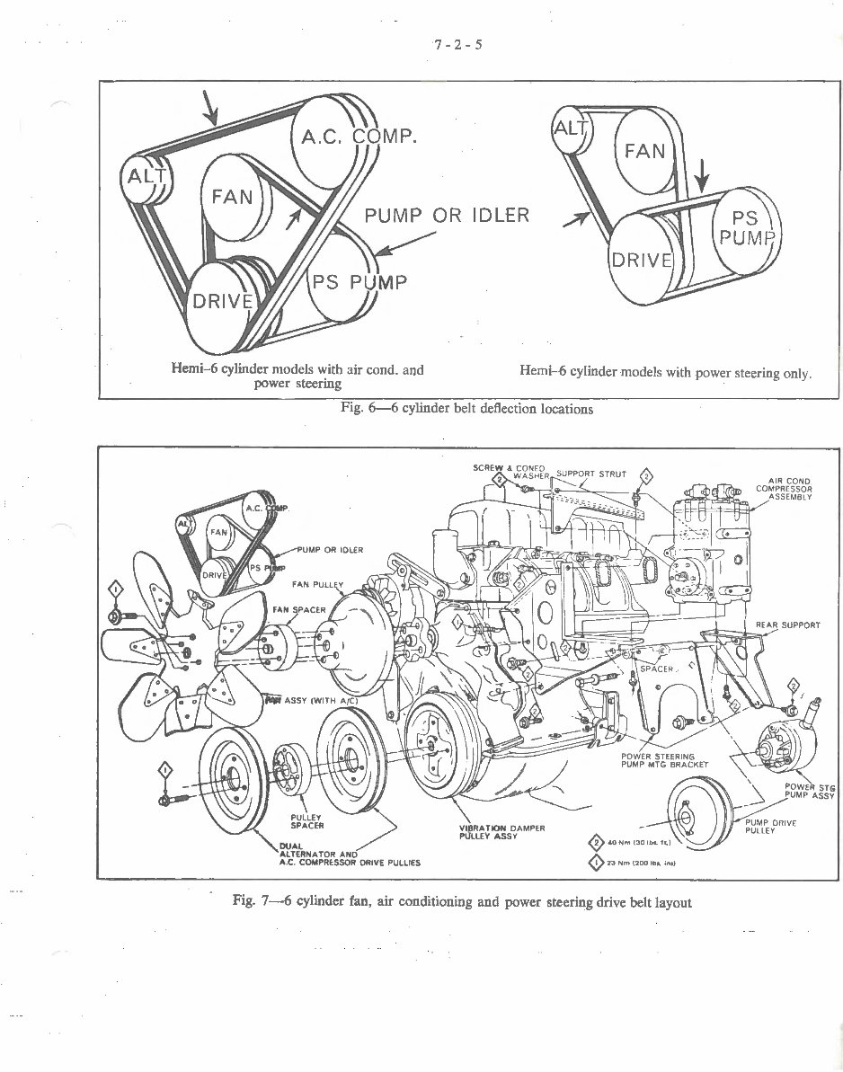
Hemi-6 cylinder models with air cond. and
power steering
7-2-5
Hemi-6 cylinder models with power steering only.
Fig. 6-6 cylinder belt deflection locations
Fig. 7-6 cylinder fan, air conditioning and power steering drive belt layout

7-2-6
I
~~/~
'
'\.~WER STG
~MP ASSY
'
-~
~.a Nm
130
lbo. t~) PUMP DRIVE PULLEY
~ 23 Nm (2110 lbo. lno)
Fig. 8-6 cylinder fan and power steering drive belt layout
DUAL BELTS-COMP. & ALT. DRIVE
WASHER (6)
ACCESSORY DRIVE PULLEY AR~ANGEMENT (9
Fig. 9- 8 cylinder accessory drive belt layout
(9 23 Nm (~ lba. ln.)
You're Reading a Preview
What's Included?
Fast Download Speeds
Online & Offline Access
Access PDF Contents & Bookmarks
Full Search Facility
Print one or all pages of your manual
$27.99
Viewed 94 Times Today


Secure transaction
What's Included?
Fast Download Speeds
Online & Offline Access
Access PDF Contents & Bookmarks
Full Search Facility
Print one or all pages of your manual
$27.99
Whether you're a professional technician or a home workshop mechanic, this Chrysler Hemi 6 Cylinder engine overhaul manual provides easy step-by-step instructions and numerous diagrams. It covers the following Chrysler Hemi 6 Cylinder engines:
- 215ci
- 245ci
- 265ci
This manual includes comprehensive information on the following topics:
- Fully bookmarked & interactive index
- General Information
- Engine Tuning
- Engine Assembly
- Piston Selection and Fitting Instructions
- Torque Specifications
- Crankshaft Reconditioning Information
- Cylinder Head
- Rocker Arm & Push Rod Assembly
- Valves & Valve Springs
- Refacing Valves and Valve Seats
- Hydraulic Tappets
- Timing Sprockets and Chain
- Timing Chain Case, Cover and Seal
- Camshaft
- Camshaft Bearing Replacement
- Cylinder Block
- Pistons
- Piston Pins
- Connecting Rods
- Crankshaft Main Journals
- Crankshaft Main Bearings
- Main Bearings Clearance Checking
- Replacement of Main Bearing Caps
- Replacement of Rear Main Bearing Oil Seal
- Engine Oiling
- Fuel Systems
- Carter BBD Type Dual Throat Carburetor
- Holley Carburetor Model 2210
- Idle Speed and Mixture Setting Procedure
- Fuel Pumps
- Emission Control Systems
- Evaporative Control System
- Cooling System
- Water Pump
- Thermostat
- Radiator
- Drive Belt Tensioning
- Fan
- Thermal Control Fan Drive
- Exhaust System
- Specifications
- Intake & Exhaust Manifold Assembly
- Exhaust Manifold Heat Control Valve
- Electrical System
- Electronic Ignition
- Alternator & Voltage Regulators
- Ignition System
- Distributor


