RENR9716-02 September 2008 Disassembly and Assembly C27 and C32 Generator Sets Engines DWB1-Up (Generator Set) SXC1-Up (Generator Set) MED1-Up (Power Module) WDR1-Up (Generator Set) SAFETY.CAT.COM
i01658146 Important Safety Information Most accidents that involve product operation, maintenance and repair are caused by failure to observe basic safety rules or precautions. An accident can often be avoided by recognizing potentially hazardous situations before an accident occurs. A person must be alert to potential hazards. This person should also have the necessary training, skills and tools to perform these functions properly. Improper operation, lubrication, maintenance or repair of this product can be dangerous and could result in injury or death. Do not operate or perform any lubrication, maintenance or repair on this product, until you have read and understood the operation, lubrication, maintenance and repair information. Safety precautions and warnings are provided in this manual and on the product. If these hazard warnings are not heeded, bodily injury or death could occur to you or to other persons. The hazards are identified by the “Safety Alert Symbol” and followed by a “Signal Word” such as “DANGER”, “WARNING” or “CAUTION”. The Safety Alert “WARNING” label is shown below. The meaning of this safety alert symbol is as follows: Attention! Become Alert! Your Safety is Involved. The message that appears under the warning explains the hazard and can be either written or pictorially presented. Operations that may cause product damage are identified by “NOTICE” labels on the product and in this publication. Caterpillar cannot anticipate every possible circumstance that might involve a potential hazard. The warnings in this publication and on the product are, therefore, not all inclusive. If a tool, procedure, work method or operating technique that is not specifically recommended by Caterpillar is used, you must satisfy yourself that it is safe for you and for others. You should also ensure that the product will not be damaged or be made unsafe by the operation, lubrication, maintenance or repair procedures that you choose. The information, specifications, and illustrations in this publication are on the basis of information that was available at the time that the publication was written. The specifications, torques, pressures, measurements, adjustments, illustrations, and other items can change at any time. These changes can affect the service that is given to the product. Obtain the complete and most current information before you start any job. Caterpillar dealers have the most current information available. When replacement parts are required for this product Caterpillar recommends using Caterpil- lar replacement parts or parts with equivalent specifications including, but not limited to, phys- ical dimensions, type, strength and material. Failure to heed this warning can lead to prema- ture failures, product damage, personal injury or death.
RENR9716-02 3 Table of Contents Table of Contents Disassembly and Assembly Section Engine - Remove ................................................... 4 Engine - Install ....................................................... 6 Fuel Priming Pump - Remove and Install .............. 9 Fuel Filter Base - Remove ................................... 10 Fuel Filter Base - Install ....................................... 10 Fuel Filter and Water Separator - Remove and Install .................................................................... 11 Fuel Transfer Pump - Remove .............................. 12 Fuel Transfer Pump - Install .................................. 12 Electronic Unit Injector - Remove ......................... 13 Electronic Unit Injector - Install ............................. 14 Electronic Unit Injector Sleeve - Remove ............. 15 Electronic Unit Injector Sleeve - Install ................. 16 Turbocharger - Remove ........................................ 17 Turbocharger - Disassemble ................................ 17 Turbocharger - Assemble .................................... 18 Turbocharger - Install ............................................ 18 Exhaust Manifold - Remove and Install ............... 19 Inlet and Exhaust Valve Springs - Remove and Install ................................................................... 20 Inlet and Exhaust Valves - Remove and Install .... 22 Inlet and Exhaust Valve Guides - Remove and Install ................................................................... 23 Inlet and Exhaust Valve Seat Inserts - Remove and Install ................................................................... 24 Engine Oil Filter Base - Remove .......................... 25 Engine Oil Filter Base - Disassemble ................... 26 Engine Oil Filter Base - Assemble ........................ 26 Engine Oil Filter Base - Install .............................. 27 Engine Oil Cooler - Remove ................................. 27 Engine Oil Cooler - Install ..................................... 28 Engine Oil Pump - Remove .................................. 28 Engine Oil Pump - Disassemble ........................... 29 Engine Oil Pump - Assemble ................................ 29 Engine Oil Pump - Install ...................................... 30 Water Pump - Remove ......................................... 31 Water Pump - Disassemble ................................. 31 Water Pump - Assemble ...................................... 32 Water Pump - Install ............................................. 33 Water Temperature Regulator Housing - Remove and Install .................................................................. 33 Cooling System Package (Radiator, Aftercooler, Fuel Cooler) - Remove ................................................ 35 Cooling System Package (Radiator, Aftercooler, Fuel Cooler) - Install .................................................... 36 Aftercooler - Remove ........................................... 38 Aftercooler - Install ............................................... 40 Radiator Core - Remove ...................................... 42 Radiator Core - Install .......................................... 44 Engine Support (Front) - Remove and Install ....... 45 Gear Group (Rear) - Remove ............................... 46 Gear Group (Rear) - Install ................................... 48 Flywheel - Remove and Install ............................. 49 Crankshaft Rear Seal - Remove ........................... 50 Crankshaft Rear Seal - Install ............................... 50 Flywheel Housing - Remove and Install .............. 51 Vibration Damper and Pulley - Remove and Install ............................................................................. 53 Crankshaft Front Seal - Remove .......................... 54 Crankshaft Front Seal - Install .............................. 55 Gear Group (Front) - Remove .............................. 55 Gear Group (Front) - Install .................................. 56 Housing (Front) - Remove .................................... 57 Housing (Front) - Install ........................................ 58 Housing (Rear) - Remove ..................................... 60 Housing (Rear) - Install ......................................... 60 Valve Mechanism Cover - Remove and Install ..... 62 Valve Mechanism Cover Base - Remove and Install ................................................................... 62 Rocker Arm and Shaft - Remove .......................... 63 Rocker Arm - Disassemble ................................... 64 Rocker Arm - Assemble ........................................ 64 Rocker Arm and Shaft - Install .............................. 65 Cylinder Head - Remove ...................................... 66 Cylinder Head - Install .......................................... 68 Camshaft - Remove .............................................. 71 Camshaft - Install .................................................. 73 Camshaft Bearings - Remove ............................... 76 Camshaft Bearings - Install ................................... 76 Engine Oil Pan - Remove and Install ................... 78 Cylinder Liner - Remove ....................................... 79 Cylinder Liner - Install ........................................... 79 Piston Cooling Jets - Remove and Install ............. 80 Pistons and Connecting Rods - Remove .............. 81 Pistons and Connecting Rods - Disassemble ....... 82 Pistons and Connecting Rods - Assemble ........... 82 Pistons and Connecting Rods - Install .................. 83 Connecting Rod Bearings - Remove .................... 84 Connecting Rod Bearings - Install ........................ 85 Crankshaft Main Bearings - Remove .................... 86 Crankshaft Main Bearings - Install ........................ 87 Crankshaft - Remove ............................................ 88 Crankshaft - Install ................................................ 90 Bearing Clearance - Check ................................... 92 Atmospheric Pressure Sensor - Remove and Install ................................................................... 93 Camshaft Position Sensor - Remove and Install .. 93 Crankshaft Position Sensor - Remove and Install .. 94 Coolant Temperature Sensor - Remove and Install ................................................................... 95 Engine Oil Pressure Sensor - Remove and Install ............................................................................. 96 Fuel Pressure Sensor - Remove and Install ......... 97 Fuel Temperature Sensor - Remove and Install ... 97 Turbocharger Outlet Pressure Sensor - Remove and Install ................................................................... 98 Inlet Air Temperature Sensor - Remove and Install ................................................................... 99 Belt Guard - Remove and Install ........................... 99 Fan Guard - Remove and Install ........................ 100 Fan - Remove and Install ................................... 101 Fan Drive - Remove and Install ......................... 102 Electronic Control Module - Remove and Install .. 103 Alternator - Remove and Install ......................... 104 Electric Starting Motor - Remove and Install ..... 105 Index Section Index ................................................................... 106
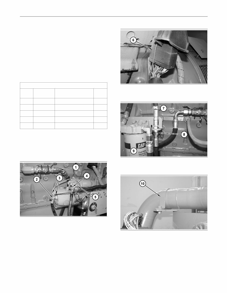
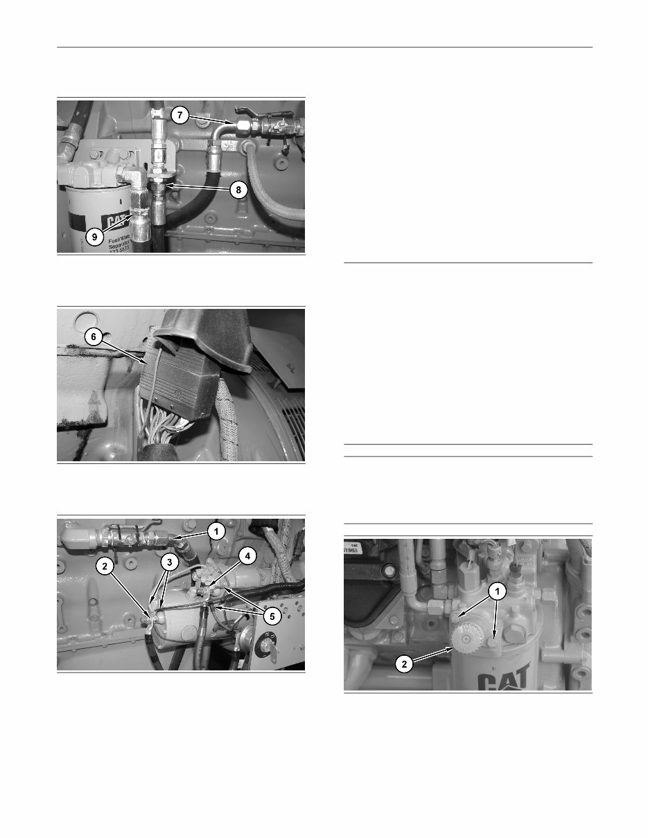
4 RENR9716-02 Disassembly and Assembly Section Disassembly and Assembly Section i02747487 Engine - Remove SMCS Code: 1000-011 Removal Procedure Table 1 Required Tools Tool Part Number Part Description Qty A 138-7573 Link Bracket 2 B 238-9586 Engine Turning Tool 1 C 1U-9200 Lever Puller Hoist 1 D 189-0411 Shackle As 2 E 6V-6146 Load Leveling Beam 1 Start By: a. Remove the cooling package. Refer to Disassembly and Assembly, “Cooling System Package (Radiator, Aftercooler, Fuel Cooler) - Remove”. g01291159 Illustration 1 1. Disconnect hose assembly (1). Disconnect cable assembly (2). Disconnect harness assemblies (3). Disconnect cable assembly (4). Disconnect harness assemblies (5). g01291160 Illustration 2 2. Disconnect harness assembly (6). g01291161 Illustration 3 3. Disconnect hose assemblies (7), (8), and (9). g01291162 Illustration 4 4. Disconnect clamp (10).
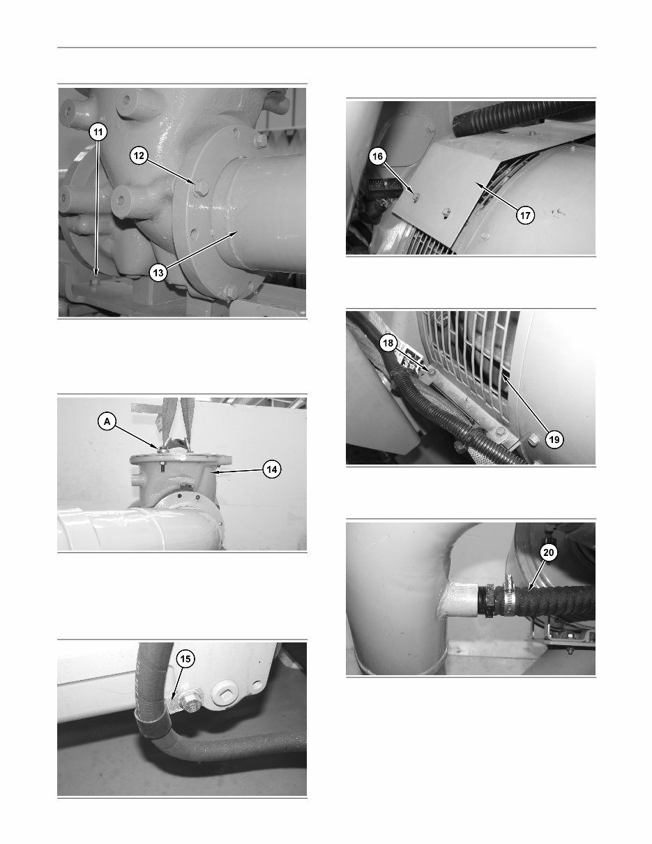
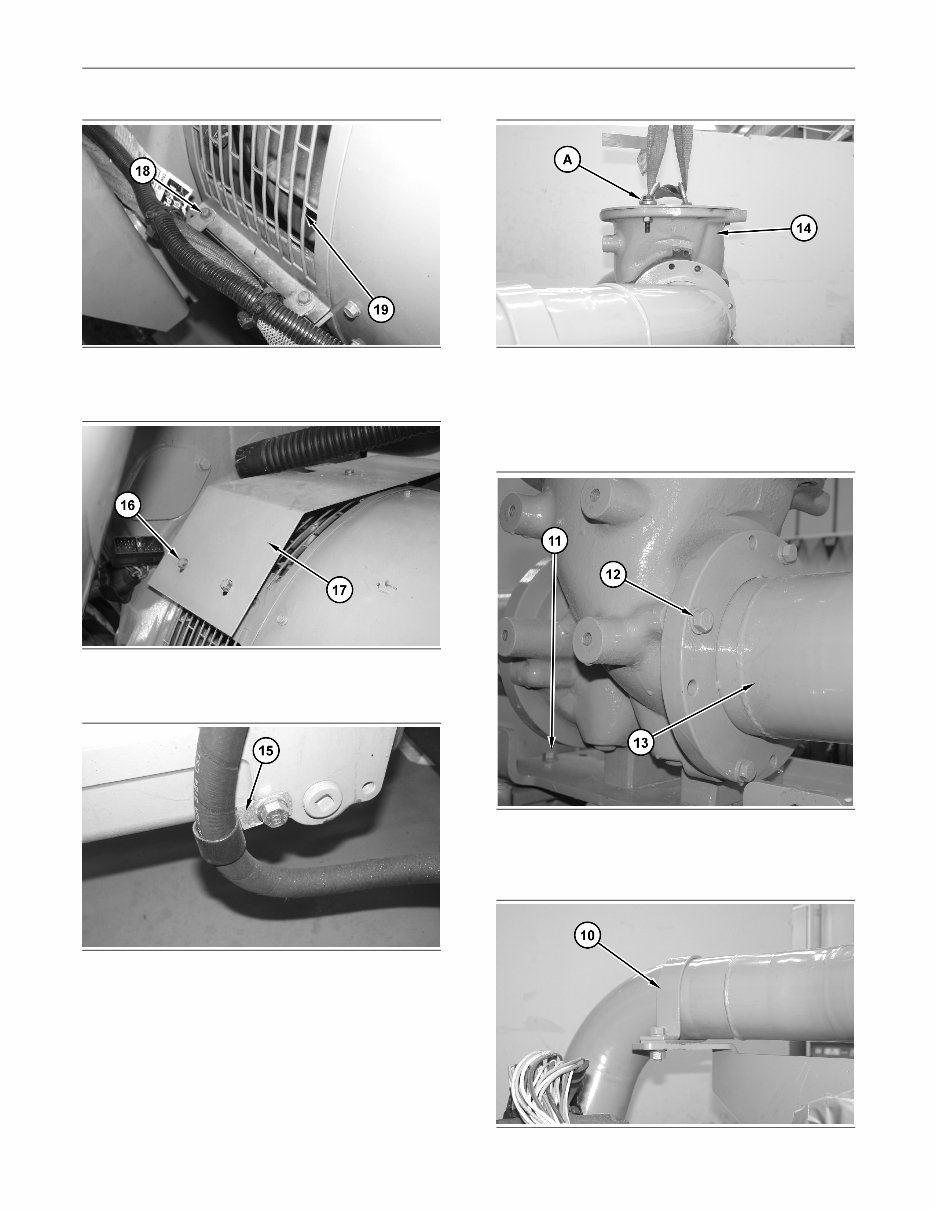
RENR9716-02 5 Disassembly and Assembly Section g01291179 Illustration 5 5. Remove bolts (11). Remove bolts (12). Repeat for the opposite side. Disconnect tube assembly (13). Repeat for the opposite side. g01291183 Illustration 6 6. Attach Tooling (A) and a suitable lifting device onto exhaust elbow (14). The weight of exhaust elbow (14) is approximately 34 kg (75 lb). Remove exhaust elbow (14). g01291186 Illustration 7 7. Disconnect clamp (15). g01291225 Illustration 8 8. Remove bolts (16). Remove guard (17). g01291227 Illustration 9 9. Remove bolts (18). Remove guard (19). g01291228 Illustration 10 10. Disconnect hose (20).
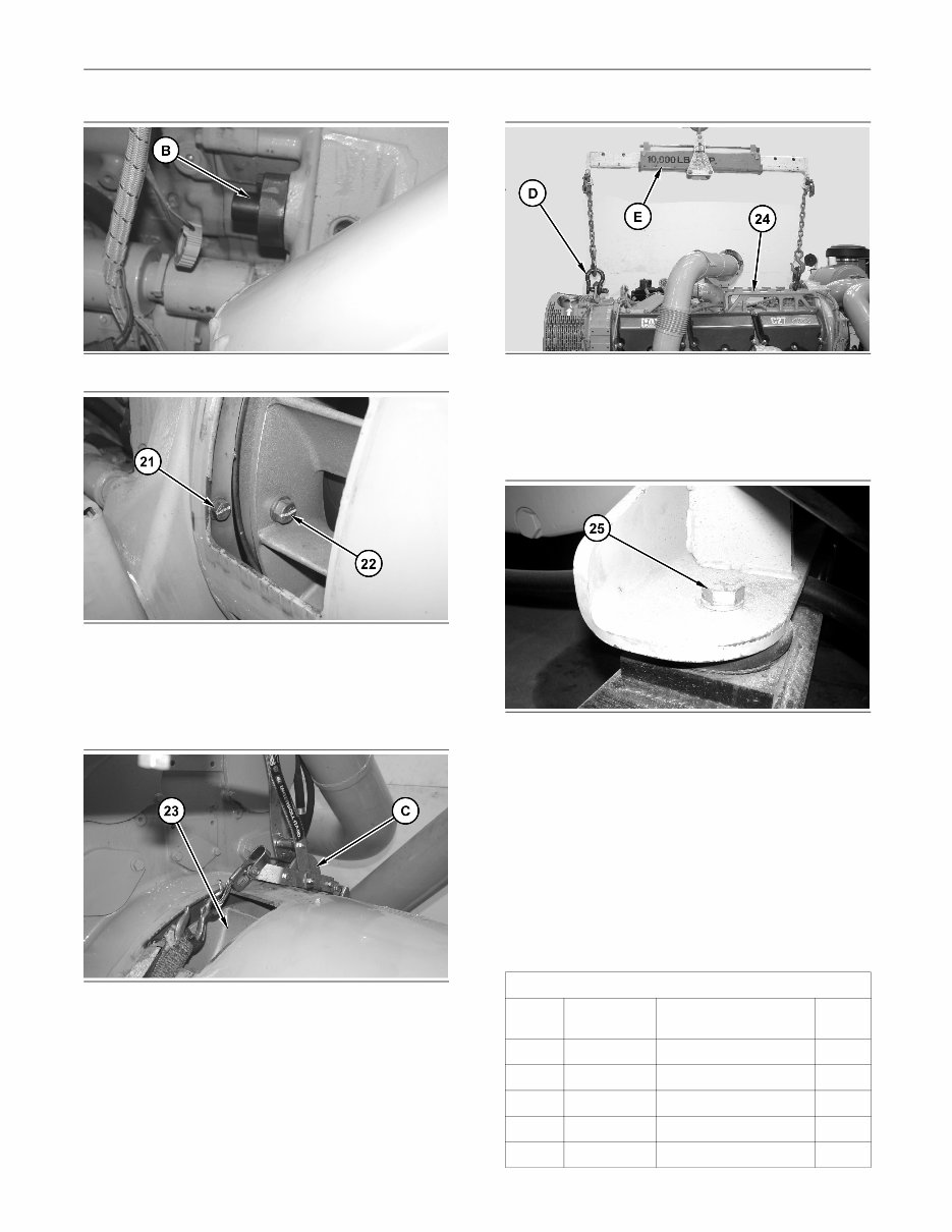
6 RENR9716-02 Disassembly and Assembly Section g01291232 Illustration 11 g01291243 Illustration 12 11. Install Tooling (B). Use Tooling (B) in order to rotate the engine. Rotate the engine in order to gain access to bolts (22). Remove bolts (22). Remove bolts (21). g01376223 Illustration 13 12. Use Tooling (C) in order to support generator rotor (23). g01291246 Illustration 14 13. Attach Tooling (D) onto engine (24). Attach Tooling (E) and a suitable lifting device onto Tooling (D). The weight of engine (24) is approximately 3527 kg (7775 lb). g01291247 Illustration 15 14. Remove mounting bolts (25). Remove engine (24) from the generator. i02747534 Engine - Install SMCS Code: 1000-012 Installation Procedure Table 2 Required Tools Tool Part Number Part Description Qty A 138-7573 Link Bracket 2 B 238-9586 Engine Turning Tool 1 C 1U-9200 Lever Puller Hoist 1 D 189-0411 Shackle As 2 E 6V-6146 Load Leveling Beam 1
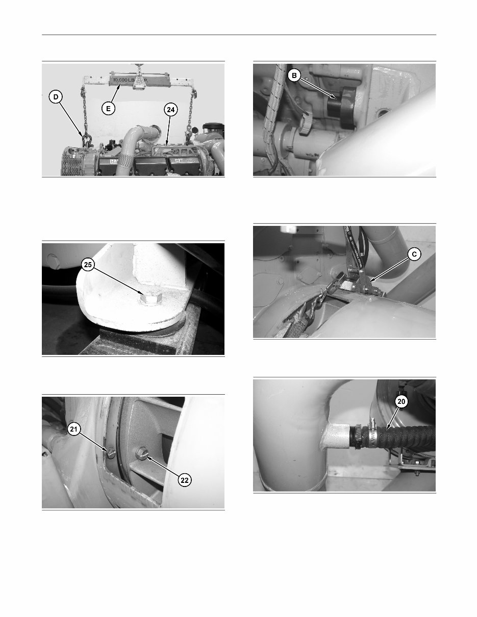
RENR9716-02 7 Disassembly and Assembly Section g01291246 Illustration 16 1. Attach Tooling (D) onto engine (24). Attach Tooling (E) and a suitable lifting device onto Tooling (D). The weight of engine (24) is approximately 3527 kg (7775 lb). Install engine (24). g01291247 Illustration 17 2. Install mounting bolts (25). g01291243 Illustration 18 g01291232 Illustration 19 3. Install bolts (21). Use Tooling (B) in order to rotate the engine. Install bolts (22). g01291245 Illustration 20 4. Remove Tooling (C). g01291228 Illustration 21 5. Connect hose (20).
8 RENR9716-02 Disassembly and Assembly Section g01291227 Illustration 22 6. Install guard (19). Install bolts (18). g01291225 Illustration 23 7. Install guard (17). Install bolts (16). g01291186 Illustration 24 8. Connect clamp (15). g01291183 Illustration 25 9. Attach Tooling (A) and a suitable lifting device onto exhaust elbow (14). The weight of exhaust elbow (14) is approximately 34 kg (75 lb). Install exhaust elbow (14). g01291179 Illustration 26 10. Connect tube assembly (13). Install bolts (12). Repeat for the opposite side. Install bolts (11). g01291162 Illustration 27
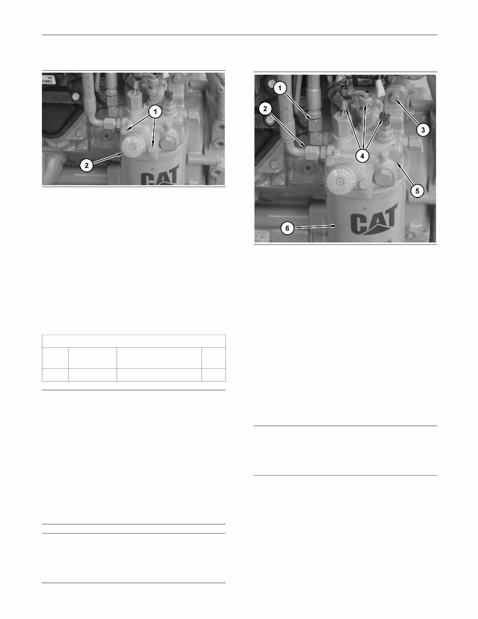
RENR9716-02 9 Disassembly and Assembly Section 11. Connect clamp (10). g01291161 Illustration 28 12. Connect hose assemblies (7), (8), and (9). g01291160 Illustration 29 13. Connect harness assembly (6). g01291159 Illustration 30 14. Connect harness assemblies (5). Connect cable assembly (4). Connect harness assemblies (3). Connect cable assembly (2). Connect hose assembly (1). End By: a. Install the cooling package. Refer to Disassembly and Assembly, “Cooling System Package (Radiator, Aftercooler, Fuel Cooler) - Install”. i02580978 Fuel Priming Pump - Remove and Install SMCS Code: 1258-010 Removal Procedure NOTICE Care must be taken to ensure that fluids are contained during performance of inspection, maintenance, test- ing, adjusting and repair of the product. Be prepared to collect the fluid with suitable containers before open- ing any compartment or disassembling any compo- nent containing fluids. Refer to Special Publication, NENG2500, “Caterpillar Tools and Shop Products Guide” for tools and supplies suitable to collect and contain fluids on Caterpillar products. Dispose of all fluids according to local regulations and mandates. NOTICE Keep all parts clean from contaminants. Contaminants may cause rapid wear and shortened component life. g01292755 Illustration 31 1. Remove bolts (1). 2. Remove fuel priming pump (2) and the gasket.
10 RENR9716-02 Disassembly and Assembly Section Installation Procedure g01292755 Illustration 32 1. Position the gasket and fuel priming pump (2) on the fuel filter base. 2. Install bolts (1). i02580993 Fuel Filter Base - Remove SMCS Code: 1262-011 Removal Procedure Table 3 Required Tools Tool Part Number Part Description Qty A 185-3630 Strap Wrench 1 NOTICE Care must be taken to ensure that fluids are contained during performance of inspection, maintenance, test- ing, adjusting and repair of the product. Be prepared to collect the fluid with suitable containers before open- ing any compartment or disassembling any compo- nent containing fluids. Refer to Special Publication, NENG2500, “Caterpillar Dealer Service Tool Catalog” for tools and supplies suitable to collect and contain fluids on Caterpillar products. Dispose of all fluids according to local regulations and mandates. NOTICE Keep all parts clean from contaminants. Contaminants may cause rapid wear and shortened component life. 1. Turn the fuel supply to the OFF position. g01292764 Illustration 33 2. Use Tooling (A) to remove fuel filter (6) from fuel filter base (5). 3. Disconnect harness assemblies (4). 4. Disconnect hose assembly (1) and hose assembly (2). 5. Remove bolts (3) and fuel filter base (5). i02581008 Fuel Filter Base - Install SMCS Code: 1262-012 Installation Procedure NOTICE Keep all parts clean from contaminants. Contaminants may cause rapid wear and shortened component life.
The Caterpillar C27 C32 Engines Workshop Repair Manual is a comprehensive guide that provides detailed instructions and procedures for repairing and maintaining Caterpillar C27 C32 engines. Whether you are a professional mechanic or a DIY enthusiast, this manual offers valuable insights into the inner workings of these engines.
Engine
Fuel filter
Fuel transfer pump
Electronic unit injector
Turbocharger
Exhaust manifold
Inlet and exhaust valves
Engine oil filter base
Water pump
Cooling system package
Aftercooler
Radiator
Gear groups
Flywheel
Crankshaft rear seal
Crankshaft front seal
Housing
Valve mechanism
Rocker arm
Cylinder head
Engine oil pan
Cylinder liner
Piston cooling jets
Connecting rod bearings
Crankshaft
Belt
Electric starting motor
This manual is available in PDF format and is compatible with all versions of Windows and Mac. It is written in English and requires Adobe Reader for viewing. By utilizing this manual, you can enhance your understanding of these engines and make informed decisions regarding their maintenance and repair. We are confident that this manual will prove to be a valuable resource for you, keeping you up-to-date and well-informed about your vehicle's engine.