Caterpillar (CAT) 3208 Diesel Engine Service & Repair Manual
What's Included?
Lifetime Access
Fast Download Speeds
Online & Offline Access
Access PDF Contents & Bookmarks
Full Search Facility
Print one or all pages of your manual
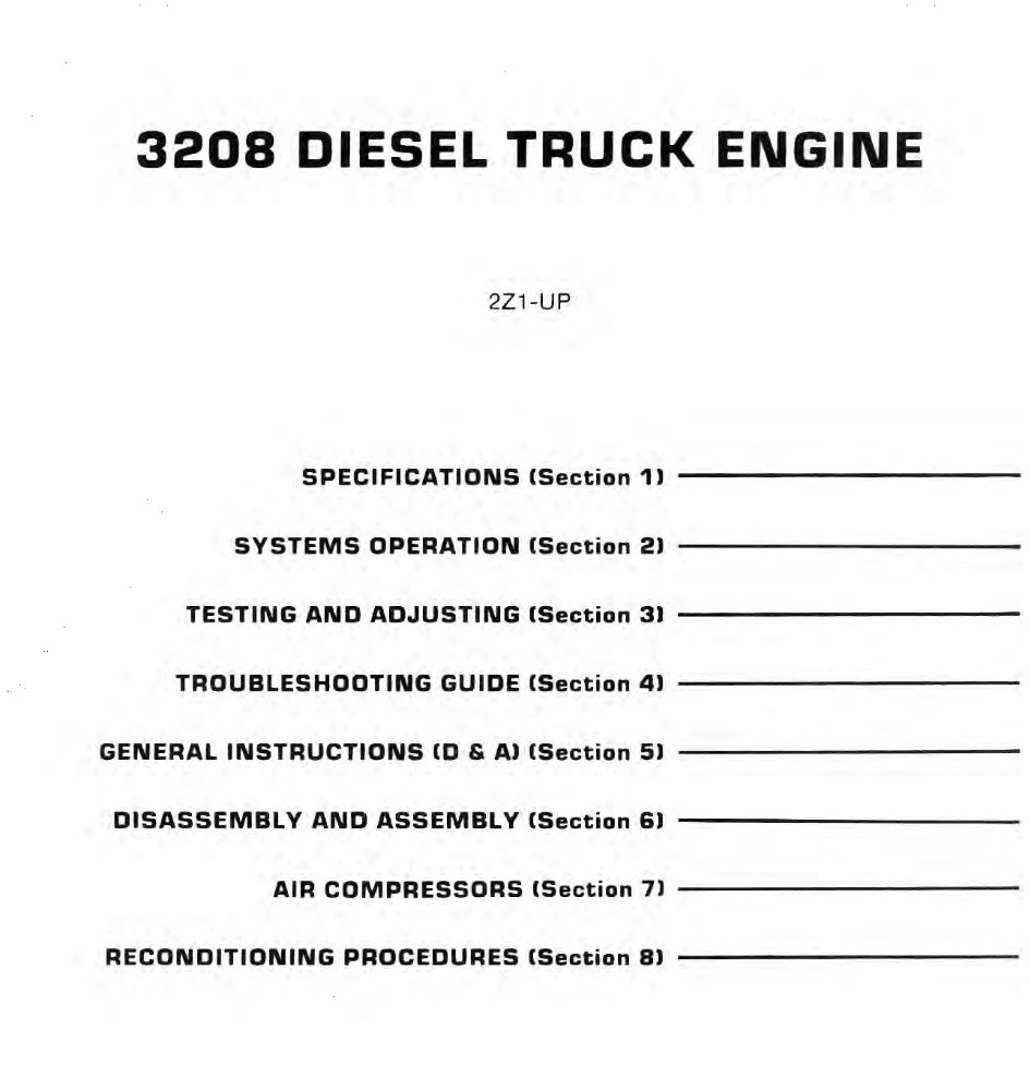
3208 DIESEL TRUCK ENGINE 2Z1-UP SPECIFICATIONS (Section 11 SYSTEMS OPERATION (Section 21 ----------- TESTING AND ADJUSTING (Section 31 TROUBLESHOOTING GUIDE (Section 41 GENERAL INSTRUCTIONS (0 & AI (Section 51 DISASSEMBLY AND ASSEMBLY (Section 61 AIR COMPRESSORS (Section 71 ---------- - RECONDITIONING PROCEDURES (Section 81
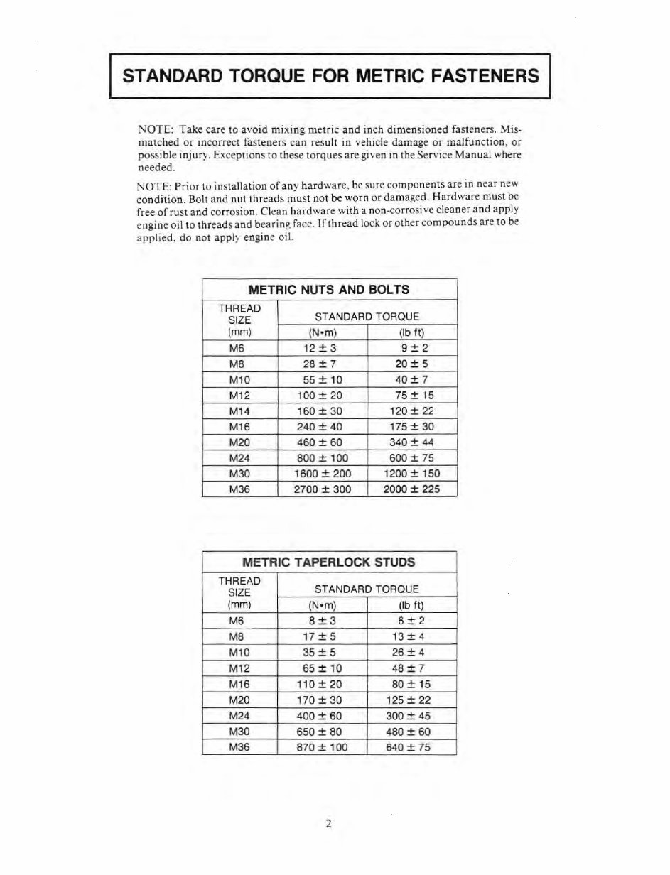
STANDARD TORQUE FOR METRIC FASTENERS NOTE: Take care to avoid mIxing metric and inch dimensioned fasteners. Mis- matched or Incorrect fasteners can result in vehicle damage or malfunction, or possible injury. Exceptions to these torques are gi ven in the SeTyice Manual where needed. NOTE: P ri or to ins tallation of any hardware, be sure components are in near new condition. Bolt and nut threads must not be worn or damaged. Hardware must be free afrust and corrosion. Clean h ardware with a non-corrosive cleaner and app ly cngine oil to threads and bea ring face. Iflhread lock or other compounds ar e to be applied, do not app ly engine oil. METRIC NUTS AND BOLTS THREAD SIZE STANDARD TORQUE (mm) (Nom) (Ib It) M6 12 + 3 9+2 M8 28 ± 7 20 ± 5 M10 55 ± 10 40 ± 7 M12 100 + 20 75 + 15 M14 160 ± 30 120±22 M16 240 + 40 175 + 30 M20 460 ± 60 I 340 ± 44 M24 800 + 100 600 + 75 M30 1600 ± 200 1200±150 M36 2700 + 300 2000 + 225 METRIC TAPER LOCK STUDS THREAD SIZE STANDARD TORQUE (mm) (N om) (Ib It) M6 8+3 6+2 M8 17 ± 5 13 ± 4 M10 35:t 5 26:t 4 M12 65 + 10 48+ 7 M16 110±20 80 ± 15 M20 170 + 30 125 + 22 M24 400 ± 60 300 ± 45 M30 650 + 80 480 + 60 M36 870 ± 100 640 ± 75 2
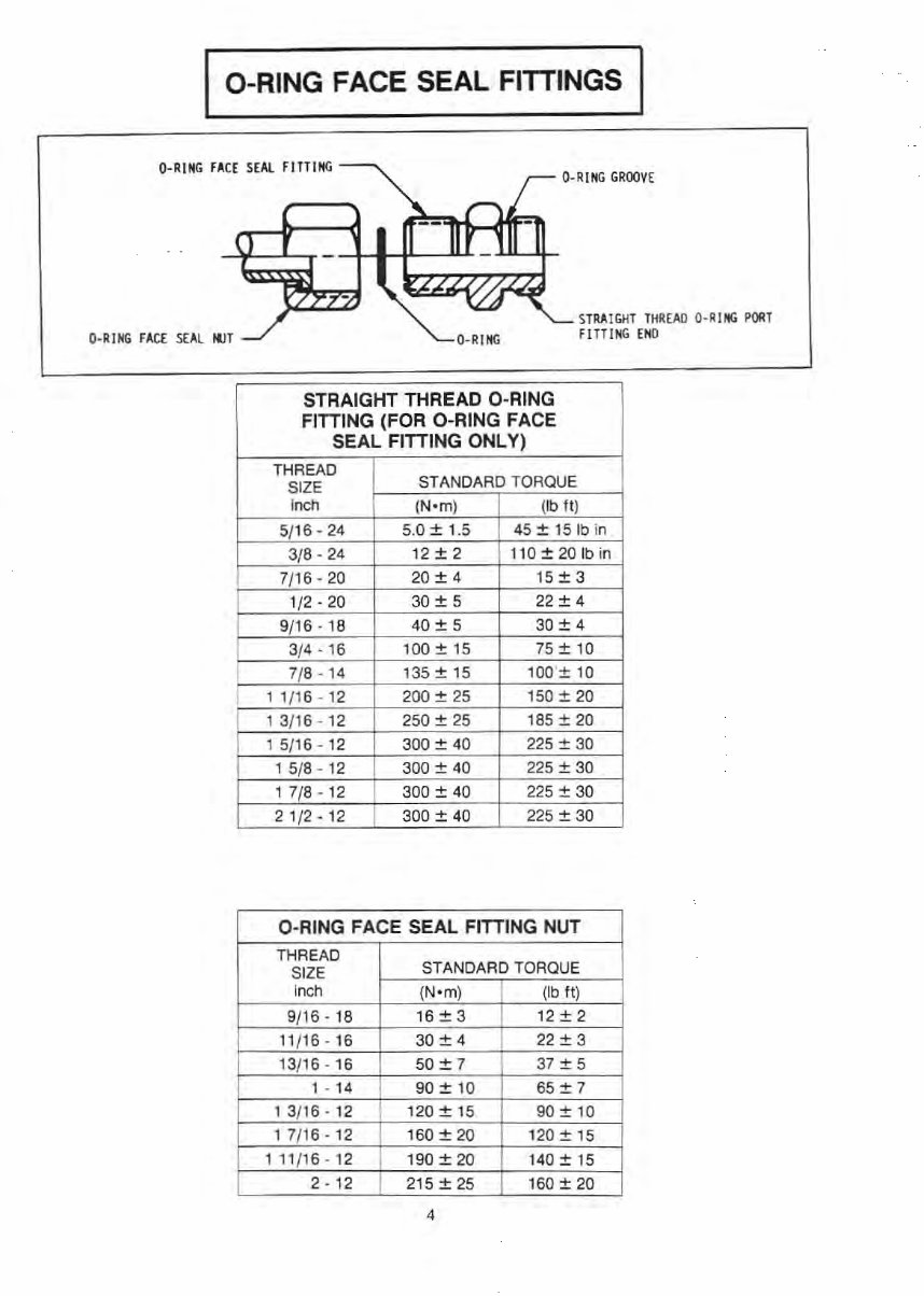
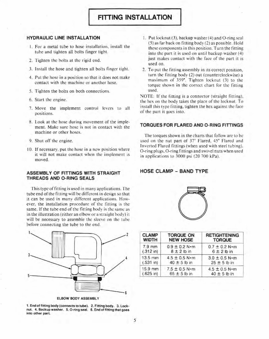
I FITTING INSTALLATION HYDRAULIC LINE INSTALLATION I. For a metal tube to hose insta ll ation. install the tu be and lighten all bolts finger tight. 2. Tighten Ihe bolts al the rigid end. 3. In stall the hose and tighten all bolts finger tight. 4. Pullhc hose in a position so that it does not make contact wi lh the mac hi ne or another hose. 5. Tighten the bolts on both connections. 6. Start the engi ne. 7. Move the implement co ntr ol levers to all IXlsitions. 8. Look at the hose durin g movement of the imple- me nt. Make s ur e hose is nol in contact with t he machine or other hoses. 9. Shut off the engine. 10 . If necessary. put the hose in a new posit ion where i! will not make co nt ac t when the implement is moved. ASSEMBLY OF FITIINGS WITH STRAIGHT THREADS AND O-RING SEALS T hi s type offit ting is used in many applications. The tube end or the fitt ing will be di lTcrc nl in design so that it can be used in many different app li calio ns. How· ever, the installation proced ur e of the fitting is the same. If the tube end o fl he fitting hody is Ihcsumc as in t he illustration (either an elbow or a slraight body) il will be necessary to assemble Ihe sleeve on Ihe luhe before connecting the tube to the end. 3 --- 6 ELBOW BODY ASSSMBL Y 1. Endof fi ning body (connecl5lo tube ). 2. Fining body. 3. Lock · nut. 4. B8Ckup wuhet. 5. O-ring !Ie81. 6. End of fining 11181 goes inlo other pl'Irt 5 I. Put locknut (3). backup washer (4) and O-ring seal (5) as far back on fitting body (2) as possible. Holtl these compo nents in this position. T urn the fitting inlO Ihe par I it is used on until backup washer (4 ) ju st ma k es conta ct wi th the fuce of the part it IS used on. 2. To putlhc fitting assembly in its correct position , turn Ihe fitting body (2) o ut (counterclockwise) a maximum of 359°. Tighten l oc knut (3) to the torque shown in the co rrect cha rt fo r the fitting used. NOTE : If the fitt ing is a connector (straight fitling), the hc.~ on the body takes the place of the locknut. To insta ll this type filling, ti gh t en the hex against Ihe faec of the part it goes into. TORQUES FOR FLARED AND O-RING FITIINGS The torques shown in the charts that follow ar c to be used on the nut pan of 37· Flared, 45" Flared and Inv erted Flared fittings (when used with steellubing). O-ring plugs, O·r ing fittings and swivel nuts when used in app li cations to 3000 psi (20 700 kPa). HOSE CLAMP - BAND TYPE CLAMP TORQUE ON RETIGHTENING WIDTH NEW HOSE TORQUE 7.9 mm 0.9 ± 0.2 N· m 0.7 ± 0.2 Nom (.312 in) 8 ± 21b in 6 ± 2 Ib in 13.5 mm 4.5 ± 0.5 Nom 3.0 ± 0.5 Nom (.53 1 in) 40±5 1bin 25±Slbin 15.9 mm 7.5 ± 0.5 N-m 4.5 ± 0.5 Nom (.625 in) 65±51bin 40±51bin
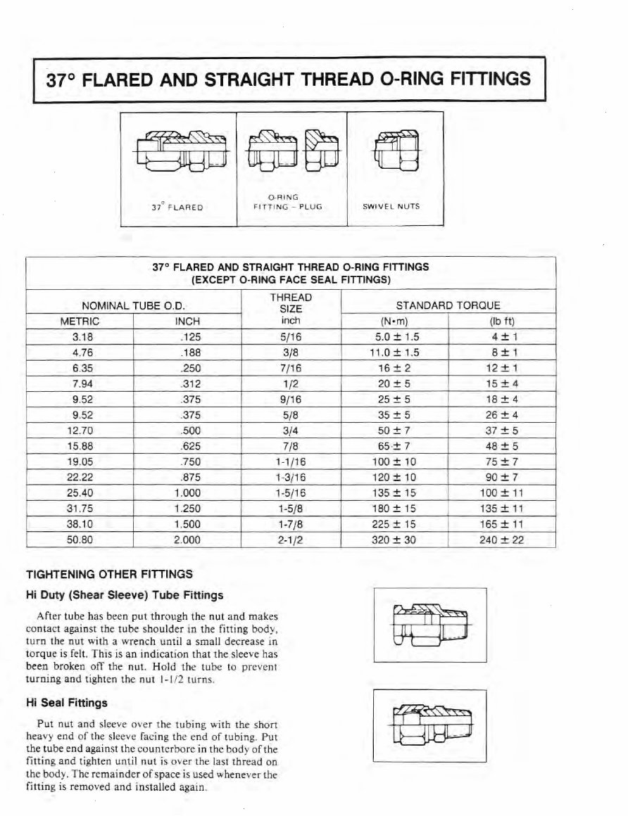
37° FLARED AND STRAIGHT THREAD O-RING FITTINGS 88n ~~ m O-RING n° FLAREO FITTING - PLUG SWIVE L NUTS 37° FLARED AND STRAIGHT THREAD O-RING FITTINGS (EXCEPT C-RING FACE SEAL FITTINGS) THREAD NOMINAL TUBE 0.0. SIZE STANDARD TORQUE METRIC INCH inch 3.18 .125 5/16 4.76 .188 3/8 6.35 .250 7/16 7,94 .312 1/2 9.52 .375 9/16 9.52 .375 5/8 12.70 .500 3/4 15.88 .625 7/8 19.05 .750 1-1/16 22.22 875 1-3/16 25.40 1.000 1-5/16 31.75 1.250 38 .1 0 1.500 50.80 2.000 TIGHTENING OTHER FITTINGS Hi Duty (Shear Sleeve) Tube Fittings After tube has be en pu t t hr ough the nut and makes contact against the tube shou lder in the fitting body, turn the nut with a wrench until a small decrease In torque is felt. This is an indication that the sleeve has been broken off the nuL Ho ld the tube to prevent turning and tighten the nut 1-112 turn s. Hi Seal Finings Put nut and sleeve over the tubing with the shan heavy e nd of the sleeve facing the end of tubing. Put the tube end against the countcrbore in the body of the fitting and tighten until nut is over the last thread on the body. The remainder of space is used whenev er the fitting is removed and installed again. 1-5/8 1-7/8 2-1 /2 (N -m) (Ib tt) 5.0 ± 1.5 4±1 11.0 + 1.5 8 +1 16 ± 2 12 ± 1 20 ± 5 15 ± 4 25 + 5 18 + 4 35 ± 5 26 ± 4 50 + 7 37 + 5 55·:!: 7 48 ± 5 100 + 10 75 + 7 120 ± 10 90 ::!: 7 135 + 15 100+11 180 ± 15 135 + 11 225 ± 15 165 ± 11 320 + 30 240 + 22
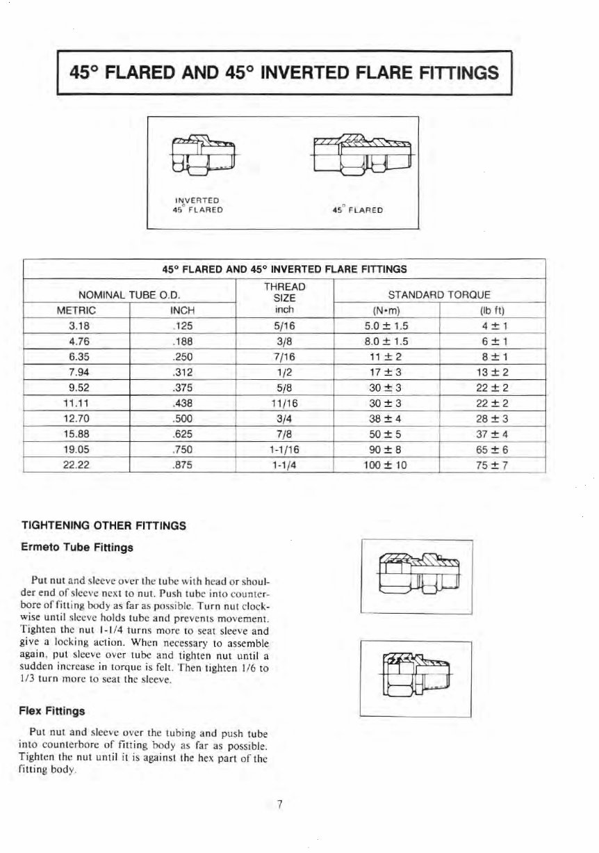
45° FLARED AND 45° INVERTED FLARE FITTINGS 4S" FLARED 45° FLARED AND 45° INVERTED FLARE FITIINGS THREAD NOMINAL TUBE 0 .0 . METR IC INCH 3. 18 .125 4.76 .188 6.35 .250 7.94 .312 9.52 .375 11 . 11 .438 12.70 .500 15.88 .625 19.05 .750 22.22 .875 TIGHTENING OTHER FITTINGS Ermeto Tube Fi ttings Put nut and slee ve over the lube with head or sho ul - der end of sleeve next to nut. Push t ube into coun tCf- bore offi lling body as far as possible. Turn nul clock- wise until sleeve holds tube and prevents movement. Tighten the nul 1-1 /4 turn s morc to seat sleeve and give a locking act ion. When necessary to assemble again, put sleeve over tube and tighten nut unt il a sudd en in crease in torque is felt. Then tighten 1!6 to 113 turn morc to seat t he sleeve. FJex FiHin gs Put nut and slecve ovcr the tu bi ng and push tube into cou nt crbo rc of filling body as far as possibl e. Tighten the nut unt il it is against the hex part of the filling body. SIZE indl 5/16 3/8 7/16 1/2 5/8 11/16 3/4 7/8 1-1 /16 1-1 /4 7 STANDARD TORQUE ( Nom) (Ib tt) 5.0 ± 1.5 4 + 1 B.O ± 1.5 6:!:1 11 + 2 8 + 1 17 ± 3 13 ± 2 30 + 3 22 + 2 30 ± 3 22 ± 2 38 + 4 28 + 3 50 + 5 37 + 4 90 :!: 8 65:!: 6 100 + 10 75+ 7
Important Safety Information Most accidents involving product operation , maintenance and repair are t;aused by fature to observe baSIC safety rules or ptecautioos. An accident can often be avoided by recognizing I?9tenlially . hazardous situations before an accident occurs. A person must be alert to potential hilzards. This person should also have the necessary tr ai ning, skills and tools \0 perform t hese funclions proper1y . Improper operation, lubrication, maintenance or repair of this product can beldangerous and could result in injury or death. Do not operate or perform any lubrication, maintenance or repair on this pr~uct. until you have read and understood the operation, lubrication, maintenance and repai r! intonnation. Safety precautions and warnings are provided in this manual and on the product . If th se hazard warnings are not heeded, bodily inju ry or death could occur to you or othe r pe rsons. The hazards are identified by the "Safety Alert Symbol" and fotlowed by a "Sign al Warp' such as "WARNING" as shown below. A WARNING The meani ng of this safety alert symbol IS as fOllows: Attention! Become Alert! Your Safety is Involved. The message that appears under the warnIng, explalnlrlg the hazard, can be either w~lIen or pictorially presented Operations that may cause product damage are identified by NOTI CE labels on the P{oduct and in this publication. Caterpillar cannot anticIpate every possibte CIrcumstance thai mIght invotve a potenti hazard. The warn I ngs in this publication and on the product are theref ore not all inclusive. If a tool, procedure, work method or operating technique not specifically recommended by Caterpillar is used, must satisfy yourself that it is safe for you and others. You should also ensure thai the product will not be damaged or made unsafe by the operation, lubrication, maintenance or repair procedures you oose. The Information, specifications, and illustrations in this publication are on the basis 01 formation available al the time it was written. The specificatIOns. torques, pressures, measure nts, adjustments, illustrations, and other items can change at any time. These changes can affect the s Nice given to the product. Obt ain the complete and most currentrnformation before starting any iO~. Caterpillar deal ers have the most current information available. For a list of the most current publIcation form numbers available, see the Service Ma nual Contents Microfiche, REG! 1 39F.
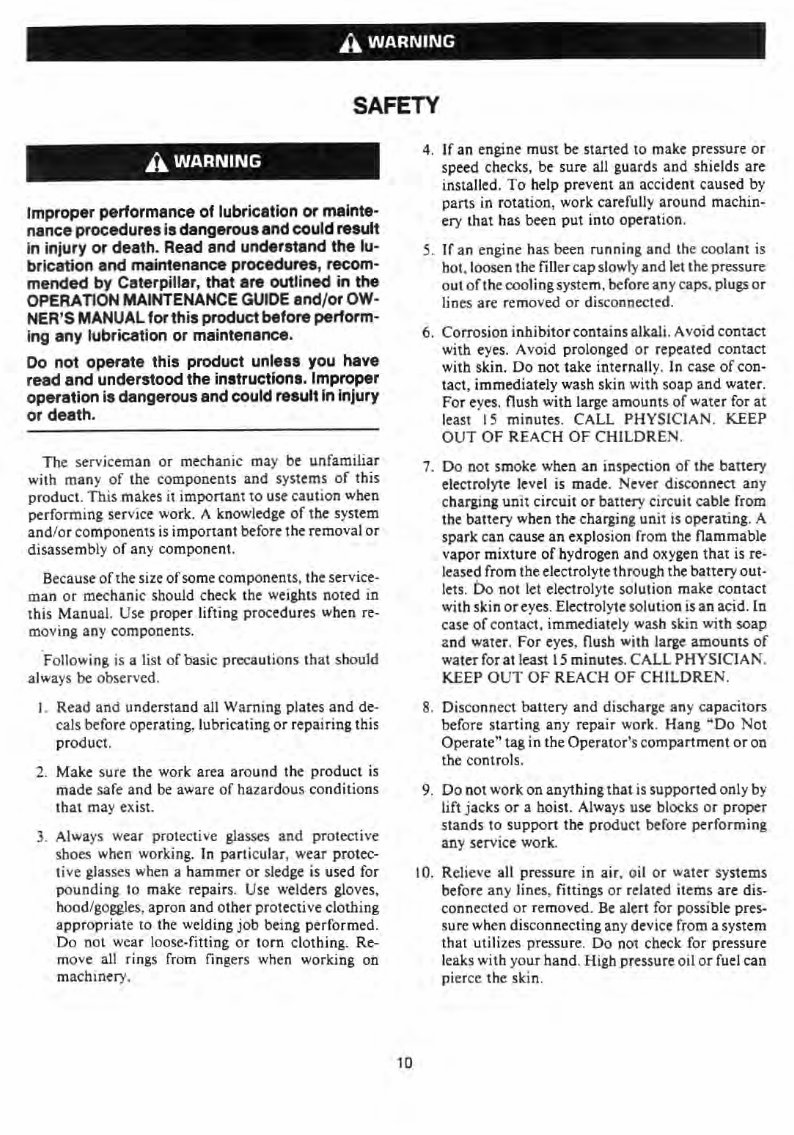
A WARNING SAFETY A WARNING Improper performance of lubrication or mainte- nance procedures is dangerous and could result in injury or death. Read and understand the lu- brication and maintenance procedures, recom- mended by Caterpillar, that are outlined in the OPERA nON MAINTENANCE GUIDE and/ or OW- NER'S MANUAL for this product before perform- ing any lubrication or maintenance. Do not operate this product unless you have read and understood the instructions. Improper operation is dangerous and could result in injury or death. The serviceman or mechanic may be unfamiliar with many of the components and systems of this product. This makes it important to use caution when performing service work. A knowledge of the system andl or components is importa nt before the removal or disassembly of any component. Because of the size of some components, the service- man or mechanic should check the weights noted in this Manual. Use proper lifting procedures when re- moving any components. 'Following is a list of basic precautions that should always be observed. 1. Read and understand all Warning plates and de- cals before operating, lubricating or repairing this product. 2. Make sure the work area around the product is made safe and be aware of hazardous conditions that may exist. 3. Always wear protective glasses and protective shoes when working. In particular, wear protec- ti ve glasses when a hammer or sledge is used for pounding to make repairs. Use welders gloves, hood/goggles, apron and other protective clothing appropriate to the welding job being performed. Do not wear loose-fitting or torn clothing. Re- move all rings from fingers when working on machinery. 10 4. If an engine must be started to make pressure or speed checks, be sure all guards and shields are installed. To help prevent an accident caused by parts in rotation, work carefully around machin- ery that has been put into operation. S. If an engine has been running and the coolant is hot, loosen the fillercapslowly and let the pressure out of the cooling system, before a.ny caps, plugs or lines are removed or disconnected. 6. Corrosion inhibitor contains alkali. Avoid contact with eyes. Avoid prolonged or repeated contact with skin. Do not take internally. In case of con- tact, immediately wash skin with soap and water. For eyes, nu sh with large amounts of water for at least I S minutes. CALL PHYSICIAN. KEEP OUT OF REACH OF CHILDREN . 7. Do not smoke when an inspection of the battery electrolyte level is made. Never disconnect any charging unit circuit or battery circuit cable from the battery when the charging unit is operating. A spark can cause an explosion from the flammable vapor mixture of hydrogen and oxygen that is re- leased from the electrolyte through the battery out- lets. Do not let electrolyte solution make contact with skin or eyes. Electrolyte solution is an acid. In case of contact. immediately wash skin with soap 2nd water. For eyes, flush with large amounts of water for at least 15 minutes. CALL PHYSICIAN . KEEP OUT OF REACH OF CHILDREN. 8. Disconnect battery and discharge any capacitors before starting any repair work. Hang "'Do Not Operate" tag in the Operator's compartment or on the controls. 9. Do not work on anything that is supported only by lift jacks or a hoist. Always use blocks or proper stands to support the product before performing any service work. 10. Relieve all pressure in air, o il or water systems before any lines, fittings or related items are dis- connected or removed. Be alert for possible pres- sure when disconnecting any device from a system that utilizes pressure. Do not check for pressure l eaks with your hand. High pressure oil or fuel can pierce the skin.
Caterpillar (CAT) 3208 Diesel Engine Service & Repair Manual
Engines covered:
10.4L 90° V8 turbo diesel
Serial Numbers Covered:
From 2Z1 and up
The Caterpillar 3208 Diesel Engine OEM Service Manual provides comprehensive factory procedures for servicing, troubleshooting, and overhauling the renowned 3208 series V8 diesel engine. Designed for professional diesel technicians and rebuilders, this manual includes factory specifications, diagnostics, and reconditioning procedures for ensuring peak engine performance and reliability.
Contents Overview:
Specifications: Torque values, clearances, wear limits, and installation guidelines for all major engine components
Systems Operation: Descriptions of fuel systems, cooling systems, lubrication, turbocharging, and air handling components
Testing & Adjusting: Step-by-step procedures for setting fuel injection timing, valve lash, governor adjustments, and boost control
Troubleshooting Guide: Diagnostic paths for performance issues, hard starting, fuel delivery faults, and smoke analysis
General Instructions: Safety warnings, tool requirements, service precautions, and standardized repair practices
Disassembly & Assembly: Factory teardown and reassembly procedures for the short block, cylinder heads, crankshaft, camshaft, pistons, and turbocharger
Air Compressor Systems: Specific coverage of integrated air compressors where equipped
Reconditioning Procedures: Guidelines for evaluating and refurbishing worn parts, including tolerances, machining limits, and reuse recommendations
Whether you're performing routine maintenance, in-frame overhauls, or full rebuilds, this OEM manual serves as the definitive technical reference for the Caterpillar 3208 engine series.
Printable: Yes Language: English Compatibility: Pretty much any electronic device, incl. PC & Mac computers, Android and Apple smartphones & tablet, etc. Requirements: Adobe Reader (free)
Recently Viewed
5,521,897Happy Clients
2,594,462eManuals
1,120,453Trusted Sellers
15Years in Business
Price:
Actual Price:
Caterpillar (CAT) 3208 Diesel Engine Service & Repair Manual