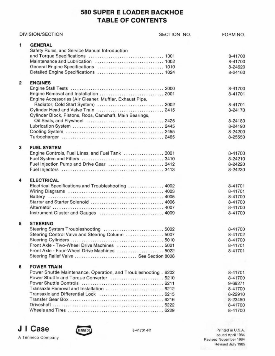
580 SUPER E LOADER BACKHOE TABLE OF CONTENTS DIVISION/S ECTION SECTION NO . 1 GENERAL Safe ty Rules, and Service Manual Int roductio n and Torque Specifications ......................... • ..... , .. 1001 Maintenance and Lubri cat ion ...................... • ........ 1002 General Engine Specifications ..... •. • .... •. • .... • .......... 1010 Detailed Engine Specifications ..... •.• .... •.• .... •.• ........ 1024 2 EN GINES Engine Stall Tests .......................................... 2000 Engine Removal and Installation ............................. 2001 Engine Accessories (Air Cleaner, Muffler , Exhaust Pipe, Radiator, Co ld Start System) .. ............................ 2002 Cylind er Head and Valve Train ., ............ , ............... 2415 Cylinder Block, Pistons, Rods, Camshaft, Main Bearings, Oil Seals, and Flywheel .................... , .............. 2425 Lubri cation System .. ,., .. " •.. ,., ............ , ... " ....... , 2445 Cooling System , ... ' ......... •.• .... •.• .... •.• .... • .• ...... 2455 Turbocharger .................. • .... • ...... •. • .. , ...• ...... 2465 3 FUEL SYSTEM Engine Controls , Fu el Lines, and Fuel Tank ....... , .•. . ...... 3001 Fuel System and Filters ......................... .. .... ...... 3410 Fuel Injection Pump and Drive Gear ............ .••.. . • ...... 3412 Fuel Injectors ................................ •. ..... • ...... 3413 4 ELECTRICAL Electrical Specifications and Troubleshooting ........ •• ...... 4002 Wiring Diagrams ..... . .............................. • ...... 4003 Battery .............. • .............................. • ...... 4005 Starter and Starter Solenoid .. ... . ...... ... ........... .. ..... 4006 Alternator . ..... ..... • .......... ..... .••. .. ...• • •.. . • " ..... 4007 Instrument Cluster and Gauges ........ • ...... •.• .... • ...... 4009 5 STEERING Steering System Tro uble shooting ............... • .. .. . ...... 5002 St ee ring Control Valve and Steering Column ..... •. .•.•.. .... 5OD7 Steering Cylinders .............................. • .. .... ..... 5010 Front Axle - Tw o-Wheel Drive Machines ............ •.. . , .... 5021 Front Axle - Four-Wheel Drive Machines ............. ... .. ... 5022 Steering Relief Valve .......... .................. See Section 8008 6 POWER TRAIN Power Shut tle Maintenance, Operation, and Troub leshooting . 6202 Power Shuttie and Torqu e Converter ........................ 6210 Power Shuttie Controls ........ , ... . ........................ 6211 Transaxle Removal and Installation ....... •.•. ...• • •. ..• .... . 6212 Transaxle and Differential Lock .......... • ...... •.• ......... 6215 Transfer Gear Box ............... .............. .. ........... 6216 Driveshaft .......... ...•. .. . ........ • .... •.• .. . •• .•... • ..... 6222 Wheels and Tires ........ .. .......... .. .. . .. . ..... . ... . ..... 6229 J I Case 8·41701-R1 A Tenneco Company FORM NO . 8-41700 8-41700 8-24620 8-24160 8-41700 8-41701 8-41701 8-24170 8-24180 8-24190 8-24200 8-25550 8-41700 8-24210 8-24220 8-24230 8-41701 8-417 01 8-41700 8-41700 8-41700 8-41700 8-41700 8-41702 8-41700 8-41701 8-41701 8-41701 8-41700 9-69271 8-41700 8-22910 8-23450 8-41700 8-41700 Printed In U.S.A. Issued April 1984 Revised November 1984 Revi sed July 1985
DIVISION/SECTION SECTION NO. 7 BRAKES Brake Pedals and Linkage, Master Cylinder, and Parking Brake ............................................ 7106 Self-Adjusting Differential Brakes ........................... 7123 8 HYDRAULI CS Hydraulic Specifications. Maintenance, Troubleshoot in g, Flowmeter Tests, and Pressure Checks .................... 8002 Cleaning the Hydraulic System .............................. 8003 Hydraulic Pump ." .. , .. .. , .. . ............... " ........ , .... 8005 Loader Conrol Valve Made by J .I. Case ...................... 8006 Loader Control Valve Made by Parker Hannifin , ......... . .... 8007 Steering Relief Valve and Quick Disconnect Cou pl ings ... . .... 8008 Three Point Hitch Control Valves ... . ........................ 8009 Cylinders ... .... . ... . ......... . ......... . .......... ...... .. 8090 Backhoe Contr ol Valve ........ .... ...... ....... . .... ... .... 8107 Stabilizer Control Valve ......................... ..• ... . ..... 8109 9 MOUNTED EQUIPMENT/ CHASSIS Air Conditioning Troubleshooting ........ . .................. 9002 Air Conditioning System ................. .. .. . .. . .. .. .. ..... 9003 Loader ................................ .... .. •... . .. . ....... 9010 Three Point Hitch .............................. . ........... 9033 ROPS Cab and ROPS Canopy . ................. ..... .. ...... 9061 Seats, Seat Belts, and Seat Supports . ...... . .. .. .. . .......... 9064 Backhoe ........ . ...................... .•. ... . .• . .. .. ...... 9100 Decals and Painting ........................ ... ...... . ...... 9201 Noise Control ........... . ...... .. ............ . ...... . ...... 9203 FO RM NO. 8-41700 8-22920 8-41701 9-69271 9-69270 8-41700 8-69272 8-41700 8-41700 8-41700 8-41700 9-6927 1 9-69270 9-69270 8-41700 8-41700 8-41700 8-41700 8-41701 8-41700 9-69270
-1- General
1001 SAFETY RULES SERVICE MANUAL INTRODUCTION AND TORQUE SPECIFICATIONS TABLE OF CONTENTS Salety Rules .. . .... . .......... ... .. ... . 1001-2 Grade 5 Bolts, Nuts. and Studs .... . .. . 1001-6 Service Manual Introduction ... . .. . .. ... 1001-4 Grade B Bolts, Nuts. and Studs ... .. .. . 1001-6 Produ ct Identification Number Steel Hydraulic Fittings ...... ... ...... 1001-7 (PIN) and Serial Number s .... , ... . .... 1001-5 Split Flange Mounting Bolts . . . ..• _ .... 1001-7 Torque Specifications • ....... .. _. _ ..... 1001-6 J I Case A Tenneco Company e Written In Clear And Simple English 8-41700 Printed In U.S.A. Issued Ap ri l 1984
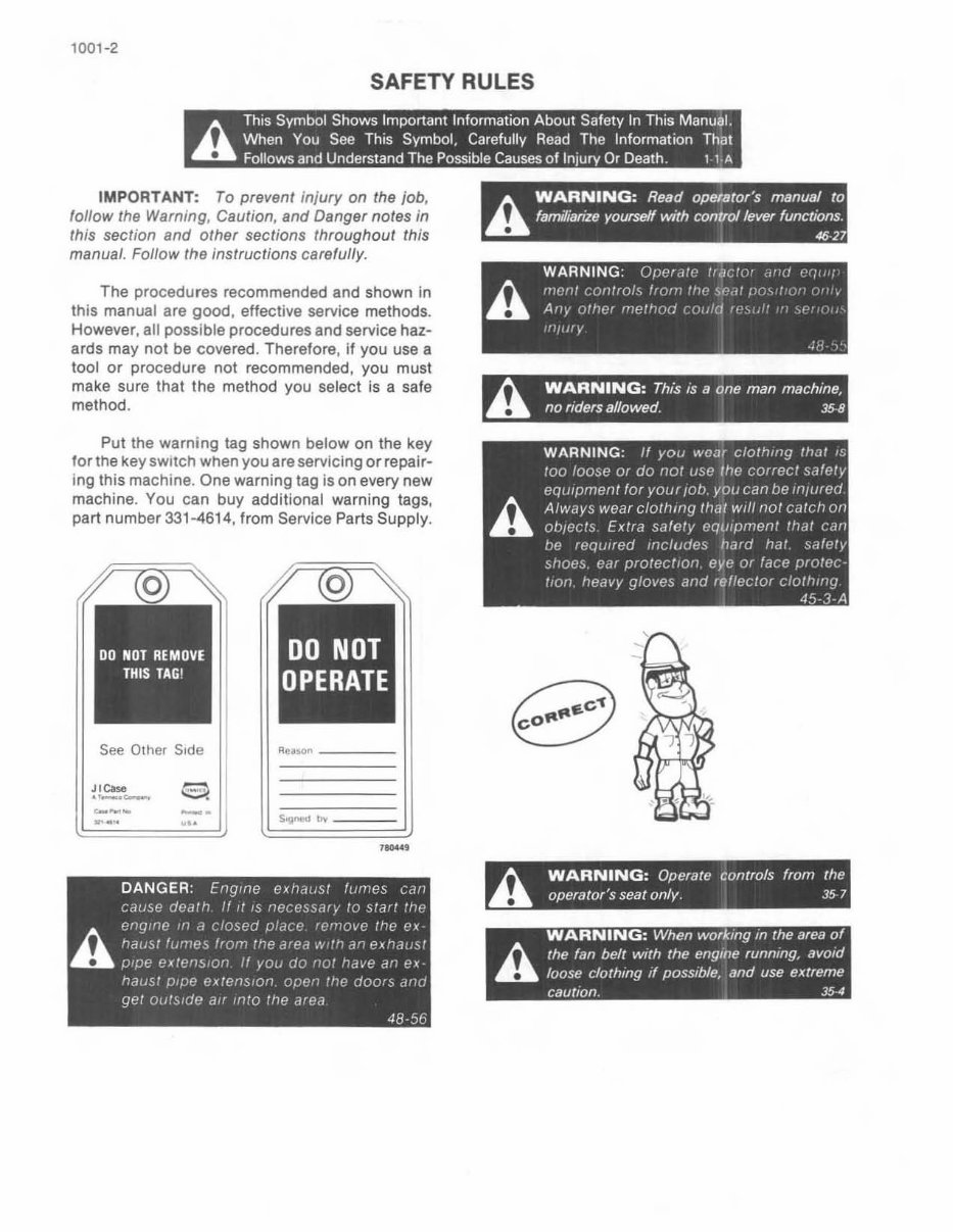
1001 -2 SAFETY RULES A This Symbol Shows Important Information About Safety In This Manual. When You See This Symbol, Ca refully Read The Information That Follows and Understand The Possible Causes of Injury Or Death 1 1 A IMPORTANT: To prevent inj ury on the job, follow the Warning. Caution. and Danger notes in this section and other sections throughout this manual, Follow the instructions carefully, The procedures recommended and shown in this manual are good, effective service methods. However. all possible procedures and service haz- ards may not be covered. Therefore. if you use a tool or procedure not recommended, you must make sure that the method you select is a safe method. Put the warning tag shown below on the key for the key switch when you are servicing or repair- i ng this machi ne. One warning tag is on every new machine. You can buy additional warni ng tags, part number 331-4614. from Service Parts Supply. See Other Side ~-- _ . .... " , ..... DANGER : Engine exh<,wsl lurnes Cdn cause dCclrt) If 1/ 's lleCe~Sd"v 10 ~Iarr Ill!' cngille ,'I d closed f),ldee .'("'love ille e;,: h hdUsr fUPle,:> Irom Ine d'ed A' :', a'i e~ '~al.S! .. p'pe e;o:lClIs,on If yOLi do '~().' "ave an Pl hausl pipe ex/ens Ion open !I~e dOOfS ,1'1(.1 gel OulSI(ie all Inro Ine dfed 48·56 A WARNING: Read operator's manual to familianze yourseH With control lever functIons 4627 WARNING OllCrd!( Ir,J{ 'I" ,"'.>' • /').. '1If'''' (()!llr()/~ /'(1r>' "'f' ~"d', ". . .. An,. 'llilel "11"//'1"1 ",'d ", > , fill I' , .. ' , h. WARNING: This IS a one man machme, .. no flders allowed 35 8 h WARNING: Operate controls from the .. operator's seat only 35 7 WARNING: When workmg m the area of h. (he fan belt With the engme runnmg, aVOid .. loose clothmg " possible, and use extreme caut IOn 354
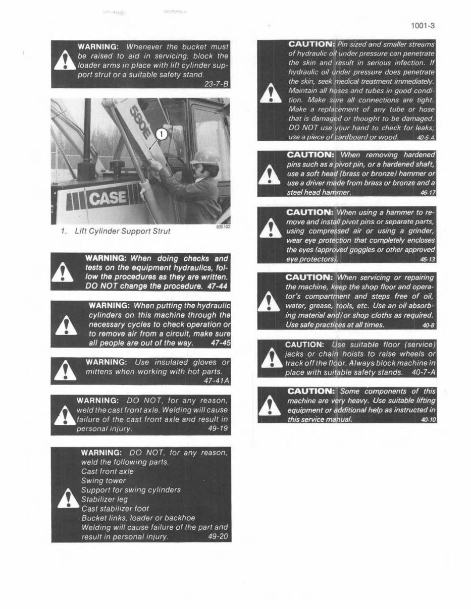
WARNING: Whenever the bucket must h be raised to aid In servICing. block. the " loader arms in place wlfh ,1ft cylmder sup- par' strut or a sUitable safety stand 23-7-8 WARNING: When doing chec ks and h tests on the equipment hydraulics. fo/- .. low the procedures as they are written. DO NO T change the procedure. 47-44 h WARNING : Use Insulated gloves Of .. mittens when workmg with hot parIs 47-41A WARNING : DO NOT for any reason h weld the cast front axle Weldmg wrllcause " failure of the cast fronl axle and resu/r In personal mlury 49- 19 WARNING: DO NOT. for any reason. weld the follOWing parIs Cast fronl axie SWing lower h Support for sWing cylinders .. Stabliller leg Cast stabilizer foot Buckel links. loader or backhoe Welding Will cause failure of the part and resull In persona/Injury 49-20 A 1001-3 CAUTION: When serviCing or repairing the machine, keep the shop floor and opera- tor's compartment and steps free of oil, water, grease, tools, etc. Use an oil absorb- ing material and/or shop cloths as required. Use safe prac tices at a/l times. 4().IJ CAUTION: Use SUItable floor (service) h lacks or cham hOists to raise wheels or .., track off the floor Always block machme In place With SUitable safety stands 40-7-A CAUTION: Some componen ts of t hiS h machine are very heavy. Use SUItable lift ing .. eqUIpment or addi t ional help as Instructed In thiS serVice manual 4().10
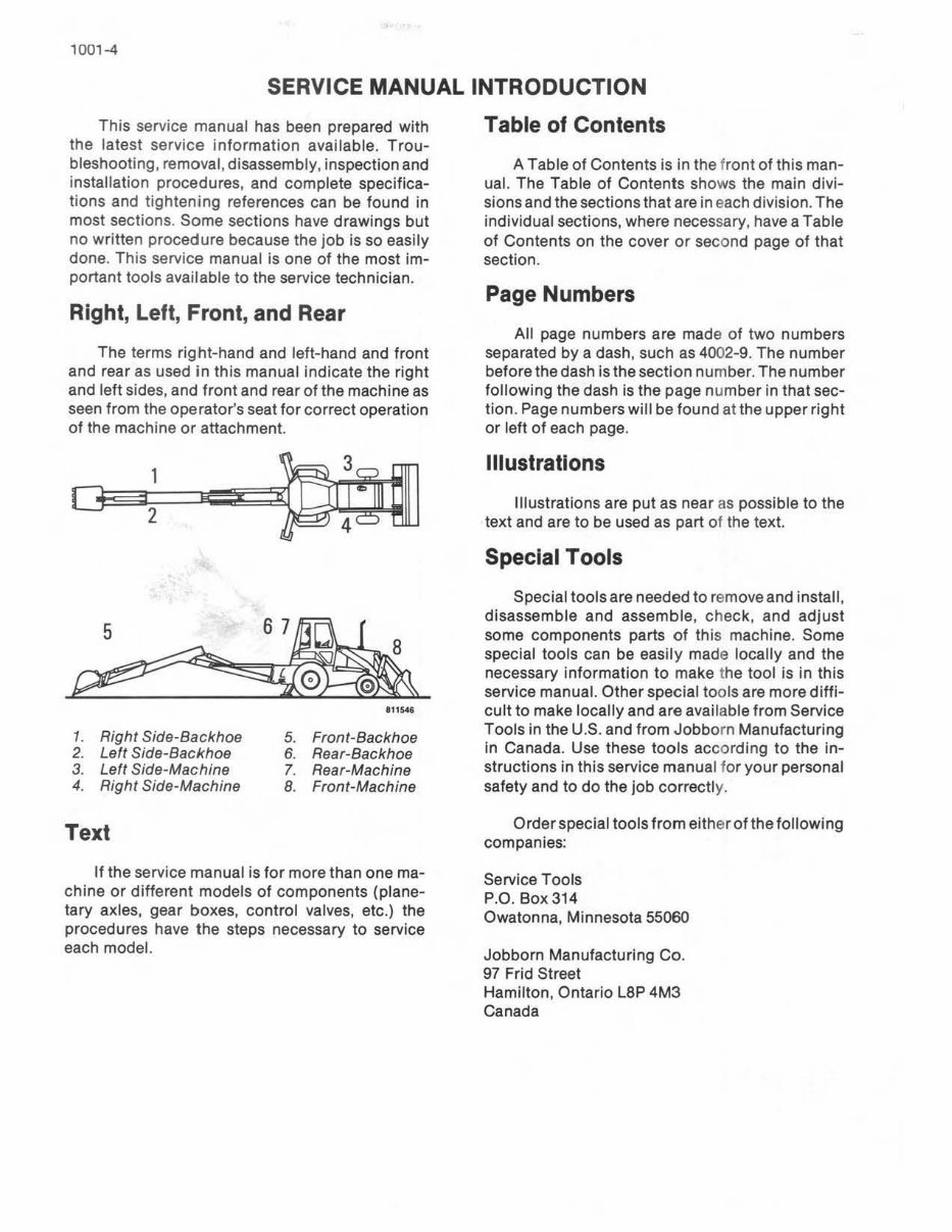
1001 -4 SERVICE MANUAL INTRODUCTION This service manual has been prepared with the latest service information available. Trou- bleshooting, removal, disassembly, inspection and installation procedures, and complete sp ecifica- tions and tightening references can be found in most sections. Some sections have drawings but no writt en procedure because the job is so easily done. Th is service manual is one of the most im- portant tools available to the service technician. Right, Left, Front, and Rear The terms right-hand and left-hand and front and rear as used in this manual indicate the right and left sides, and front and rear of the machine as seen from the operator's seat for correct operation of the ma chi ne or attachment. 5 67~ ~ '1 1541 1. Right Side-Backhoe 5. Front-Backhoe 2. Left Side-Backhoe 6. Rear-Backhoe 3. Left Side-Machine 7. Rear-Machine 4. Right Side-Machine 8. Fro nt -Machine Text If the service manual is for more than one ma- chine or different models of comp on ents (plane- tary axles, gear boxes, control valves, etc.) the procedures have the steps necessary to service each model. Table of Contents A Table of Contents is in the front of this man- ual. The Tab le of Contents shows the main divi- sions and the sections that are in each division. The indi vi du al sections, where necessary, have a Table of Contents on t he cover or se cond page of that section. Page Numbers All page numbers are mad e of two numbers separated by a dash, such as 4002-9. The number before the dash is the section number. The number following the dash is the page number in that sec- tion. Page numbers will be found at the upper right or left of ea ch page. illustrations Ill us trations are put as near as possible to t he text and are to be used as part of the text. Special Tools Special tools are needed to remove and install. disassemble and assemble, check. and adjust some components parts of this machine. Some special tools can be easily made locally and the necessary infor mation to make the tool is in this service manual. Other special tools are more diff i- cult to make locally and are ava ilable from Service Tools in the U.S. and from Jobborn Manufacturing in Canada. Use these tools according to the in- structio ns in this servi ce manual for you r personal safety and to do the job correctl y. Order special tools from either of t he following companies: SeNice Tools P.O. Box 314 Owatonna, Minnesota 55060 Jobborn Manufacturing Co . 97 Frid Street Hamilton, Ontario Lap 4M3 Canada
1001-5 Product Identification Number (PIN) and Serial Numbers NOTE: A serial number plate is also on some components such as the starter, alternator, pumps, etc. • - ; • PRODUCT IDENTIFICATION NUMBER SN OF THREE· POINT HITCH '3'"'' PART HUMBER AND SN OF 4·IN·' BUCKET SN OF POWER SHUTTLE SN OF ROP S CANOPY SN OF FRONT DRIVE AXLE
The Case 580E Engines Repair Manual is a comprehensive guide for repairing and maintaining your Case 580E engine. Whether you are a professional mechanic or a DIY enthusiast, this workshop manual is an essential tool for ensuring the optimal performance of your engine.
This manual features detailed instructions covering removal, installation, disassembly, and assembly of your engine. It also includes an electrical wiring diagram and hydraulic schematic, allowing for easy troubleshooting of electrical or hydraulic issues.
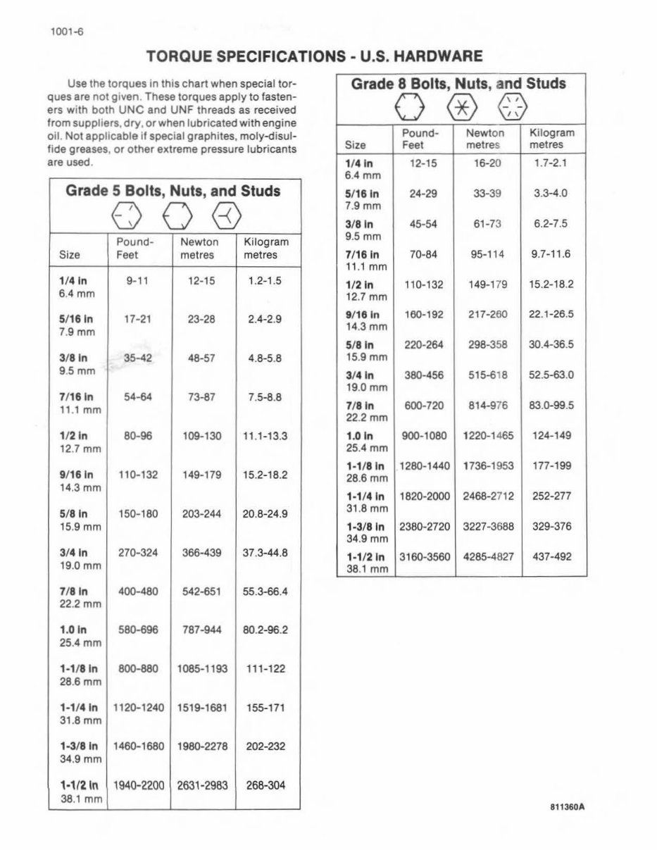
Diagnostic information and specifications are provided to quickly identify and resolve any problems that may arise. The torque values in the manual ensure that every bolt and nut is tightened to the correct specifications, preventing potential damage or failure.