

VANGUARD 3CYL. Diesel & TURBO-Diesel Engine Repair Manual
What's Included?
Fast Download Speeds
Online & Offline Access
Access PDF Contents & Bookmarks
Full Search Facility
Print one or all pages of your manual

FORM MS-1055-5/02 2002 BRIGGS & STRATTON DAIHATSU LLC PRINTED IN U.S.A.
REPAIR MANUAL
For 3 Cylinder LiquidĆCooled Diesel Engines
FOREWORD
The information, procedures and specifications provided in this repair manual are current as of the date of
publication and subject to change without notice. Appropriate changes will be included in the next revision of this
manual.
Note: Manufacturing standards may vary from service specifications. Always refer to the service procedures and
specifications in this manual when engine service is required.
GENERAL REPAIR INSTRUCTIONS
Before attempting a B&SD engine overhaul or a tune-up, it is necessary that your shop be equipped with proper tools,
equipment and mechanics who are thoroughly familiar with Briggs & Stratton engine design and construction. With
your shop thus equipped, this book will serve as a guide in performing the various steps necessary to do a complete
and satisfactory job. Use only genuine replacement parts. Always use recommended service tools.
This engine is designed and manufactured using metric dimensions. The English equivalents provided may have been
rounded up or down to the closest numerical interpretation of the metric dimension.
The terms Inspect, Check, Test and Replace are used as follows:
INSPECT Visual inspection look for signs of wear, scoring, cracks, stripped threads, etc.
CHECK Measure by means of plug gauges, micrometer, feeler gauges, scale, etc.
TEST Analyze with proper test equipment.
REPLACE This usually means to take off the old part and reassemble it or replace it with a new one.
Disassembly
As engine is being disassembled, mark parts which are part of an assembly, to prevent interchanging. Arrange parts in
an orderly manner, keeping parts which are an assembly together.
Visually inspect each part as it is removed look for signs of wear, scoring, cracks, stripped threads, etc.
Inspection and Measurement
Carefully check parts that can be reconditioned and/or reused.
Replace any parts that are not within specification.
Clean parts to be reused
Clean or wash disassembled parts.
Assemble
Use a torque wrench to torque bolts and nuts to required specifications.
Replace all gaskets, cotter pins, oil seals and O-rings.
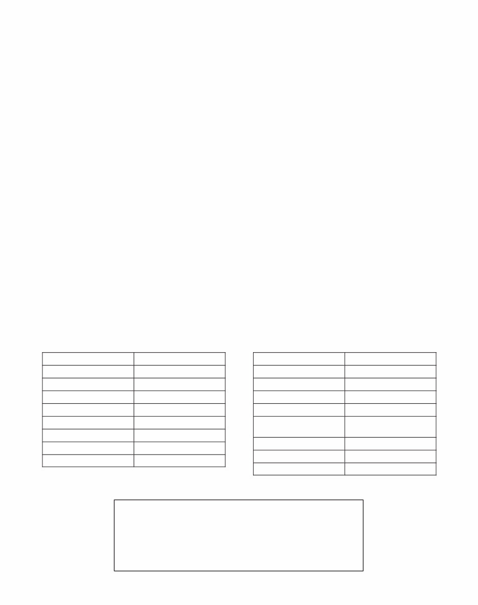
ABBREVIATIONS
Abbreviation Meaning
ASSY Assembly
BDC Bottom Dead Center
DT Diesel Turbocharger
EX Exhaust
ID Inside Diameter
IN Intake
LH Left Hand
MP Multi-purpose
Abbreviation Meaning
OD Outside Diameter
OPT Optional
O/S Oversize
RH Right Hand
SAE Society of Automotive
Engineers
T/C Turbocharger
TDC Top Dead Center
U/S Undersize
Copyright " 2002 by Briggs & Stratton Corporation
All rights reserved. No part of this material may be reproduced or
transmitted, in any form or by any means, electronic or mechanical,
including photocopying, recording or by any information storage
and retrieval system, without permission in writing from Briggs &
Stratton Corporation.

TABLE OF CONTENTS
See Pages II and III for Section Contents
GENERAL INFORMATION Section 1 . . . . . . . . . . . . . . . . . . . . . . . . . . . . . . . . . . . . .
CYLINDER HEAD AND VALVES Section 2 . . . . . . . . . . . . . . . . . . . . . . . . . . . . . . . .
TIMING GEARS AND GEAR CASE Section 3 . . . . . . . . . . . . . . . . . . . . . . . . . . . . . .
FLYWHEEL AND REAR SEAL RETAINER Section 4 . . . . . . . . . . . . . . . . . . . . . . .
CYLINDER BLOCK DISASSEMBLY Section 5 . . . . . . . . . . . . . . . . . . . . . . . . . . . . .
CYLINDER BLOCK INSPECTION AND REPAIR Section 6 . . . . . . . . . . . . . . . . . .
CRANKSHAFT, CAMSHAFT AND BEARINGS Section 7 . . . . . . . . . . . . . . . . . . . .
PISTON, RINGS AND CONNECTING ROD
INSPECTION AND ASSEMBLY Section 8 . . . . . . . . . . . . . . . . . . . . . . . . . . . . . . . . .
CYLINDER BLOCK ASSEMBLY Section 9 . . . . . . . . . . . . . . . . . . . . . . . . . . . . . . . .
FUEL SYSTEM AND RELATED COMPONENTS Section 10 . . . . . . . . . . . . . . . . .
ELECTRICAL SYSTEMS Section 11 . . . . . . . . . . . . . . . . . . . . . . . . . . . . . . . . . . . . . .
LUBRICATION SYSTEM Section 12 . . . . . . . . . . . . . . . . . . . . . . . . . . . . . . . . . . . . . .
COOLING SYSTEM Section 13 . . . . . . . . . . . . . . . . . . . . . . . . . . . . . . . . . . . . . . . . . .
TOOLS Section 14 . . . . . . . . . . . . . . . . . . . . . . . . . . . . . . . . . . . . . . . . . . . . . . . . . . . . .
I

SECTION CONTENTS
IV
1
Section 1
GENERAL INFORMATION
Engine Identification
In The Interest Of Safety
Engine Views
Engine Specifications And Data
Fastener Specifications
Briggs & Stratton Numerical Number System
Maintenance Schedule
2
Section 2
CYLINDER HEAD AND VALVES
Remove Cylinder Head
Disassemble Cylinder Head
Inspect And Repair
Cylinder Head
Valve Guides
Valves
Disassemble Rocker Arm Shaft
Assemble Rocker Arm Shaft
Assemble Cylinder Head
Install Cylinder Head
Adjust Valves
3
Section 3
TIMING GEARS AND GEAR CASE
Remove Timing Gear Cover And Gears
Checking Gears
Remove Gear Case
Replace Timing Gear Cover Oil Seal
Assemble Timing Gear Case And Gears
4
Section 4
FLYWHEEL AND REAR SEAL RETAINER
Removing Flywheel And Rear Seal Retainer
Replacing Oil Seal
Installing Rear Seal Retainer And Flywheel
Install Oil Pan
5
Section 5
CYLINDER BLOCK DISASSEMBLY
Engine Stand Fixture
Cylinder Block Disassembly
6
Section 6
CYLINDER BLOCK INSPECTION AND
REPAIR
Checking Cylinder Block
Replacing Camshaft Bearing
Replacing Camshaft Plug
7
Section 7
CRANKSHAFT, CAMSHAFT AND BEARINGS
Checking Crankshaft
Checking Main Bearing Clearances
Checking Connecting Rod Bearing Clearances
Checking Crankshaft End Play
Checking Camshaft
8
Section 8
PISTON, RINGS AND CONNECTING ROD
INSPECTION AND ASSEMBLY
Disassemble Piston And Connecting Rod
Checking Piston And Rings
Checking Piston Pin And Connecting Rod
Assemble Piston And Connecting Rod
Assemble Piston Rings To Piston
9
Section 9
CYLINDER BLOCK ASSEMBLY
Install Crankshaft
Install Pistons And Connecting Rods
General Assembly
Oil Pickup Tube
Rear Seal Retainer And Starter Motor
Flywheel
Install Timing Gear Case, Camshaft And
Gears
Install Oil Pan
Install Alternator
10
Section 10
FUEL SYSTEM AND RELATED
COMPONENTS
General Information
Injector Pump Timing Specifications
Checking Injector Pump Timing

SECTION CONTENTS (contd)
III
Adjusting Injector Pump Timing
Injectors
Remove Injectors
Checking Injectors
Install Injectors
Fuel Filter General
Draining Water Collector
Change Fuel Filter
Fuel Shut-Off Solenoid
Checking Fuel Shut-Off Solenoid
Wiring
Injector Pump Identification
Engine Speed Identification Chart
Adjust Idle Speed
Adjust Top No Load Speed
11
Section 11
ELECTRICAL SYSTEMS
Electrical System Components
Glow Plug System
Glow Plug Specifications
Remove Glow Plugs
Test Equipment
Testing Glow Plug
Preheat Timer And Glow Relay
Testing Preheat Timer
Testing Glow Relay
Keyswitches
Charging Systems
14 Amp Charging System
Test Equipment
Testing Alternator AC Output
Testing Regulator-Rectifier DC
Output
Testing Charge Indicator Bulb And
Wiring
40 Amp Charging System
Test Equipment
Testing Alternator DC Output
Disassemble Alternator
Checking Bearings
Install Ball Bearing
Check Brushes
Check Regulator
Check Rectifier
Assemble Alternator
Starter System
Starter Current Draw Test Installed
Test Equipment
Testing Starter
Starter Current Draw Test No Load
Testing Starter (No Load)
Starter Solenoid
Equipment To Test Solenoid
Testing Solenoid
Remove Solenoid
Check Pinion And Clutch Assembly
Assemble Pinion And Clutch Assembly
Install Solenoid
Install Solenoid Contacts And Plunger
Disassemble Starter Motor
Inspect Armature Commutator
Inspect Brushes
Replace Brushes
Assemble Starter Motor
Wiring Diagrams
40 Amp Wiring Diagram
14 Amp Wiring Diagrams
12
Section 12
LUBRICATION SYSTEM
Description
Change Oil
Change Oil Filter
Check Oil Pressure
Disassemble Gear Case
Remove Oil Pump
Assemble Gear Case
Install Oil Pump
13
Section 13
COOLING SYSTEM
General Information
Checking Cooling System
Pressure Testing Cooling System
Testing Radiator Cap
Changing Coolant
Thermostat
Removing Thermostat
Checking Thermostat
Installing Thermostat
Water Pump
Inspecting Water Pump
Removing Water Pump
Installing Water Pump

SECTION CONTENTS
IV
14
Section 14
TURBOCHARGER
General Information
Turbocharger Lubrication System
Turbocharger Cooling System
Turbocharger Waste Gate
Turbocharger Pressure Control System
Crankcase Bloeby Recirculating System
Checking Waste Gate Actuator
Servicing And Operating Information
Remove Turbocharger
Checking Turbocharger
Install Turbocharger
Installation Of Coolant Inlet Tube
1 MAY 2002
Section 1
General Information
BRIGGS & STRATTON DAIHATSU 3 CYLINDER
LIQUID-COOLED DIESEL ENGINE REPAIR MANUAL (MS-1055)
Section Contents
Page
ENGINE IDENTIFICATION 1 . . . . . . . . . . . . . . . . . . . . . . . . . . . . . . . . . . . . . . . . . . . . . . . . . . . . . . . . . . . . . . . . . . . . . . . .
IN THE INTEREST OF SAFETY 2 . . . . . . . . . . . . . . . . . . . . . . . . . . . . . . . . . . . . . . . . . . . . . . . . . . . . . . . . . . . . . . . . . . . .
ENGINE VIEWS 3 . . . . . . . . . . . . . . . . . . . . . . . . . . . . . . . . . . . . . . . . . . . . . . . . . . . . . . . . . . . . . . . . . . . . . . . . . . . . . . . . . .
ENGINE SPECIFICATIONS AND DATA 4 . . . . . . . . . . . . . . . . . . . . . . . . . . . . . . . . . . . . . . . . . . . . . . . . . . . . . . . . . . . . .
FASTENER SPECIFICATIONS 9 . . . . . . . . . . . . . . . . . . . . . . . . . . . . . . . . . . . . . . . . . . . . . . . . . . . . . . . . . . . . . . . . . . . .
BRIGGS & STRATTON NUMERICAL NUMBER SYSTEM 10 . . . . . . . . . . . . . . . . . . . . . . . . . . . . . . . . . . . . . . . . . . . . .
MAINTENANCE SCHEDULE 11 . . . . . . . . . . . . . . . . . . . . . . . . . . . . . . . . . . . . . . . . . . . . . . . . . . . . . . . . . . . . . . . . . . . . .
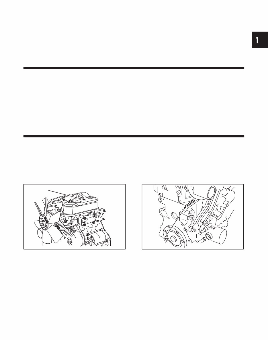
ENGINE IDENTIFICATION NUMBERS
The engine model and type number are located on the vale cover, Fig. 1. The serial number is stamped into the right
side of the cylinder block, behind the intake manifold, Fig. 2.
Fig. 1 Engine Model And Type Number
MODEL AND
TYPE NO.
Fig. 2 Engine Serial Number
SERIAL NO.
2
GENERAL INFORMATION
IN THE INTEREST OF SAFETY
This safety alert symbol indicates that this
message involves personal safety. Signal
words danger, warning and caution indicate
hazard degree. Death, personal injury and/OR
property damage may occur unless instruc-
tions are followed carefully.
WARNING: DO NOT
1. DO NOT run engine in an enclosed area. Exhaust
gases contain carbon monoxide, an odorless and
deadly poison.
2. DO NOT place hands or feet near moving or
rotating parts. Keep all guards in place.
3. DO NOT place hands or feet near electric cooling
fan (if equipped). Fan may start suddenly, de-
pending on coolant temperature.
4. DO NOT store, spill, or use diesel fuel near an
open flame, or devices such as a stove, furnace,
or water heater which use a pilot light or devices
which can create a spark.
5. DO NOT refuel indoors where area is not well
ventilated. Outdoor refueling is preferred.
6. DO NOT fill fuel tank while engine is running. Allow
engine to cool for 2 minutes before refueling.
Store fuel in approved, correct color safety
containers.
7. DO NOT remove fuel tank cap while engine is
running.
8. DO NOT operate engine when smell of fuel is
present or other explosive conditions exist.
9. DO NOT operate engine if diesel fuel is spilled.
Move machine away from the spill and avoid
creating any ignition until the spill has been
wiped up.
10. DO NOT smoke when filling fuel tank.
11. DO NOT tamper with maximum speed set screw
or full load set screw of the injector pump which
may increase the governed engine speed.
12. DO NOT tamper with the engine speed selected
by the original equipment manufacturer.
13. DO NOT operate engine with a damaged muffler
or without muffler. Inspect periodically and
replace, if necessary. If engine is equipped with
muffler deflector(s), inspect periodically and
replace, if necessary, with correct deflector(s).
14. DO NOT operate engine with an accumulation of
grass, leaves, dirt or other combustible material in
the muffler area.
15. DO NOT use this engine on any forest covered,
brush covered, or grass covered unimproved land
unless a spark arrester is installed on the muffler.
The arrester must be maintained in effective
working order by the operator. In the State of
California the above is required by law (Section
4442 of the California Public Resources Code).
Other states may have similar laws. Federal laws
apply on federal lands.
16. DO NOT touch hot muffler(s) or cylinder(s)
because contact may cause burns.
17. DO NOT remove the radiator cap while the engine
is hot. To avoid scalding from hot coolant or steam
blowing out of the radiator, use extreme care when
removing the radiator cap. If possible, wait for
engine to cool. If not possible, wrap a thick rag
around cap while removing. To release pressure,
slowly turn cap counter clockwise to the first stop.
When all pressure has been released, press down
on cap and continue turning.
18. DO NOT start or run engine with air cleaner or air
cleaner cover removed.
WARNING: DO
1. ALWAYS DO disconnect the negative wire from
the battery terminal when servicing the engine or
equipment, TO PREVENT ACCIDENTAL
STARTING.
2. ALWAYS DO disconnect fuel shut off solenoid wire
from injection pump before checking compression,
TO PREVENT ACCIDENTAL STARTING.
3. DO wear eye protection when operating or
repairing equipment.
4. DO keep governor parts free of grass and other
debris which can affect engine speed.
5. DO examine muffler(s) periodically to be sure it is
functioning effectively. A worn or leaking
muffler(s) should be repaired or replaced as
necessary.
6. DO check fuel lines and fittings frequently for
cracks or leaks. Replace if necessary.
CAUTION:
DO use clean fresh diesel fuel with a minimum of 40
cetane.
DO NOT use kerosene. The injection pump requires
diesel fuel for lubrication. Damage to the injection
pump and/or engine may result if kerosene is used.
NOTE: Use Original Briggs & Stratton-Daihatsu
Service Replacement Parts when
servicing your engine. Authorized Briggs
& Stratton-Daihatsu Service Centers
carry a stock of such parts. The use of
Briggs & Stratton-Daihatsu parts
preserves the original design of your
engine. Imitation replacement parts may
not fit or function as original Briggs &
Stratton-Daihatsu parts and can expose
the operator to potential personal injury.
Contact any Authorized Briggs &
Stratton-Daihatsu Service Center for
Original Briggs & Stratton-Daihatsu
Replacement Parts.
3
GENERAL INFORMATION
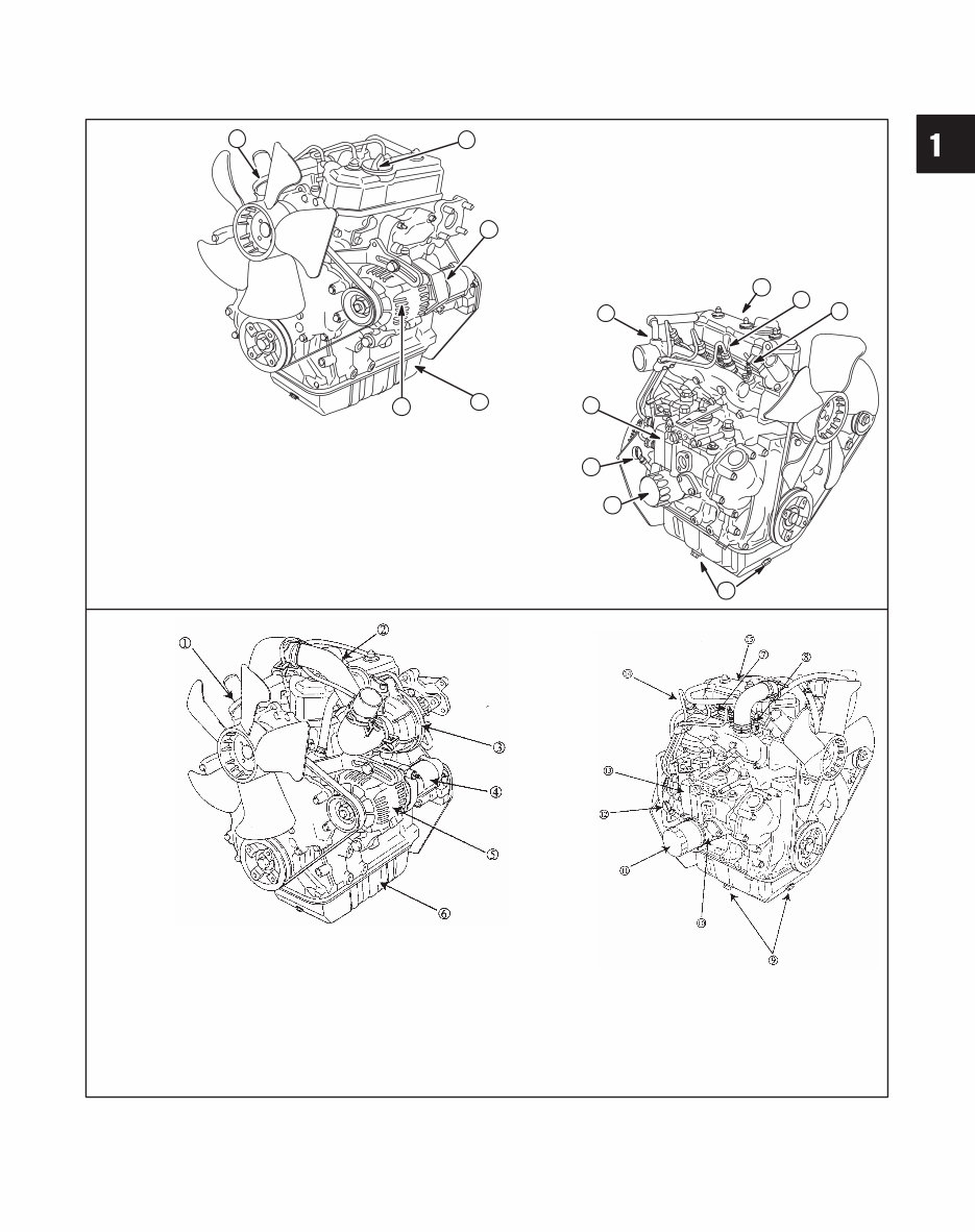
ENGINE VIEWS
1. Thermostat
2. Oil filler cap
3. Electric starter
4. Oil pan
5. Alternator
2
3
5
4
Diesel
1
11
6. Injector nozzle
7. Glow plug
8. Oil drains
9. Oil filter
10. Dipstick
11. Injector pump
12. Engine Date code
xxxxxxxx
13. Engine Model & Type number
xxxxxx xxxx-xx
7
10
13
9
6
8
12
1. Thermostat
2. Oil filler cap
3. Turbocharger
4. Electric starter
5. Alternator
6. Oil pan
Turbo-charged
Diesel
7. Injector nozzle
8. Glow plug
9. Oil drains
10. Oil cooler
(if equipped)
11. Oil filter
12. Dipstick
13. Injector pump
14. Engine Date code
xxxxxxxx
15. Engine Model & Type number
xxxxxx xxxx-xx
4
GENERAL INFORMATION
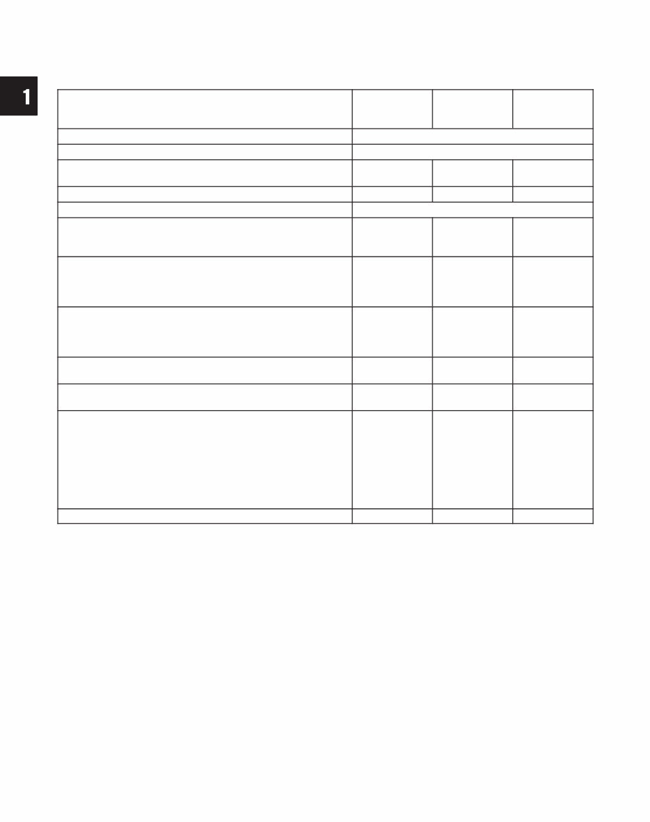
ENGINE SPECIFICATIONS
Model 432447 522447
582447
@58A447
@588447
Type Diesel, 4-cycle, 3 cylinder, in-line, liquid cooled
Valve mechanism OHV, gear driven
Bore x stroke mm (in)
68 x 64
(2.680 x 2.520)
68 x 78
(2.680 x 3.070)
72 x 78
(2.834 x 3.070)
Piston displacement cc (cu in) 697 (42.5) 850 (52.0) 952 (58.1)
Firing order 1-2-3 (front, center, back)
Compression ratio 25.0:1 24.4:1
24.0:1
@ 24.8:1
Compression pressure (normal)
@
300 RPM Bar
Engine at operating temperature (psi)
glow plugs removed
33.0
(469)
32.0
(455)
34.0
(498)
@ 37
(526)
Compression pressure (minimum)
@
300 RPM Bar
Engine at operating temperature (psi)
glow plugs removed
30.0
(425)
29.0
(412)
30.5
(433)
@ 27
(384)
Gross HP @ 3600 RPM 19.5 23.6
26.5
@ 28.0
Gross Torque @ 2400 RPM 32.5 40.0
44.1
@ 49.2
Dimensions (L x W x H) mm (in)
441.8 x 440.4 x
523.9
(17.4 x 17.34 x
20.6)
434.4 x 442.9 x
548.4
(17.1 x 17.44 x
21.59)
434.4 x 442.9
x 548.4
(17.1 x 17.44 x
21.59)
@ 434.4 x
447.5 x 559.0
(17.1 x 17.62 x
22.01)
Dry weight kg (lbs) 76 (168) 78 (172) 89 (196)
You're Reading a Preview
What's Included?
Fast Download Speeds
Online & Offline Access
Access PDF Contents & Bookmarks
Full Search Facility
Print one or all pages of your manual
$37.99
Viewed 56 Times Today


Secure transaction
What's Included?
Fast Download Speeds
Online & Offline Access
Access PDF Contents & Bookmarks
Full Search Facility
Print one or all pages of your manual
$37.99
This workshop repair service manual is designed for the VANGUARD 3CYL. DIESEL & TURBO-DIESEL ENGINE, applicable to various engine models:
- 697 cc 3-CILINDER, 4-CYCLE, IN-LINE, LIQUID-COOLED, OHV, GEAR DRIVEN DIESEL ENGINE for 432447 model
- 850 cc 3-CILINDER, 4-CYCLE, IN-LINE, LIQUID-COOLED, OHV, GEAR DRIVEN DIESEL ENGINE for 522447 model
- 952 cc 3-CILINDER, 4-CYCLE, IN-LINE, LIQUID-COOLED, OHV, GEAR DRIVEN DIESEL ENGINE for 582447/58A447/588447 model
The manual includes detailed information on the following:
- General information
- Cylinder head & valves
- Timing gear & gear case
- Flywheel system
- Seal retainer
- Cylinder block disassembly, inspection, and repair
- Crankshaft/camshaft/bearings
- Piston/rings/connecting rod inspection and assembly
- Fuel system and fuel injector pump
- Electrical system, glow plug system, charging system, and starter system
- Lubrication system and cooling system
- Turbocharger
- Wiring diagram
This comprehensive manual is available in .PDF format and features detailed exploded views, step-by-step written procedures with pictures and diagrams, and is fully printable. It is an essential resource for both professional mechanics and DIY enthusiasts for repairs, maintenance, and servicing of VANGUARD 3CYL. DIESEL & TURBO-DIESEL ENGINES.


