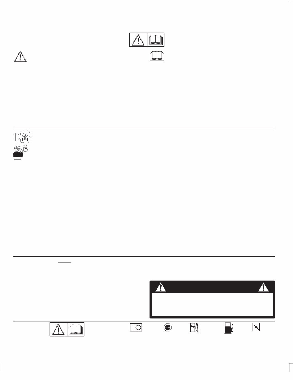
In the USA and Canada, a 24 hour hot line, 1-800-233-3723, has a menu of pre-recorded messages offering you engine maintenance information. 2 Maintenance, replacement or repair of the emission control devices and systems may be performed by any nonroad en- gine repair establishment or individual. However, to obtain no charge repairs under the terms and provisions of the Briggs & Stratton warranty statement, any service or emission control part repair or replacement must be performed by a factory authorized dealer. In the Interest of Safety This safety alert symbol indicates that this message involves personal safety . Words danger , warning and caution indicate degree of hazard. Death, personal injury and/or property damage may occur unless instructions are followed carefully. You are not ready to operate this engine if you have not read and understood the following safety items. Read this entire owner ’s manual and the operating instructions of the equipment this engine powers. The Briggs & Stratton engine you bought with your equipment is made of the finest material in a state-of-the-art manufacturing facility. Please understand that Briggs & Stratton sells engines to original equipment manufacturers. It also sells to others i n the distribution chain who may sell to the ultimate consumer , an equipment manufacturer , another distributor or a dealer . As a resu lt, Briggs & Stratton does not necessarily know the application on which the engine will be placed. For that reason, you should carefully read and understand the operating instructions of the equipment on which your engine is placed before you operate it. You should also understand that there are equipment applications for which Briggs & Stratton does not approve the use of its engines. Briggs & Stratton engines are not to be used on vehicles with less than 4 wheels. They include motor bikes, aircraft products and All Terrain Vehicles. Moreover, Briggs & Stratton does not approve of its engines being used in competitive events . F0R THAT REASON, BRIGGS & STRATTON ENGINES ARE NOT AUTHORIZED FOR ANY OF THESE APPLICATIONS. Fail- ure to follow this warning could result in death, serious injury (including paralysis) or property damage. DO NOT run engine in an enclosed area. (Exhaust gases contain carbon monoxide, an odorless and deadly poison.) DO NOT remove fuel tank cap nor fill fuel tank while engine is hot or running. DO NOT refuel indoors or in an unventilated area. ( Allow engine to cool 2 min- utes before refueling.) DO NOT place hands or feet near moving or rotating parts. DO NOT store, spill, or use gasoline near an open flame, nor near an appliance like a stove, furnace, or water heater that uses a pilot light or can create a spark. DO NOT refuel indoors or in an unventilated area. DO NOT operate or tip engine/equipment at such a severe angle that causes gasoline spillage. DO NOT operate engine if gasoline is spilled or when smell of gasoline is present or other explosive conditions exist. (Move equipment away from spill and avoid any ignition until gasoline has evaporated.) DO NOT transport engine with fuel in tank or fuel shut-of f valve open. DO NOT choke carburetor to stop engine, especially in an en- closed vehicle. (Whenever possible, gradually reduce engine speed before stopping.) DO NOT tamper with governor springs, links or other parts to increase engine speed. (Run engine at speed set for equipment manufacturer.) DO NOT check for spark with spark plug removed. (Use an approved tester.) DO NOT crank engine with spark plug removed. (If engine is flooded, place throttle in FAST and crank until engine starts.) DO NOT strike flywheel with a hammer or hard object as this may cause flywheel to shatter in operation. (To remove flywheel, use Briggs & Stratton approved tools only.) DO NOT operate engine without a muffler. (Inspect periodically and replace if worn or leaking. If engine is equipped with muf- fler deflector, inspect periodically and replace if necessary. Re- placement parts must be same as on original equipment.) DO NOT operate engine with an accumulation of grass, leaves or other combustible material in muffler area. DO NOT use this engine on any forest covered, brush cov- ered, or grass covered unimproved land unless a spark ar- rester is installed on muf fler. The spark arrester must be main- tained in working order by the owner and/or operator. In the State of California the above is required by law (Section 4442 of the California Public Resources Code). Other states may have similar laws. Federal laws apply on federal lands. DO NOT touch hot muffler, cylinder, or fins which can cause burns. DO NOT start engine with air cleaner or air cleaner cover re- moved (or cover over carburetor air intake, if Sno/Gard engine). DO NOT attempt to start engine with cutting blade loose or re- moved. (Blade must be tight, otherwise a kickback may occur.) ✔ PULL starter cord slowly until resistance is felt. Then pull cord rapidly to avoid kickback and prevent hand or arm injury. ✔ PREVENT ACCIDENTAL STARTING by removing spark plug wire from spark plug when servicing engine or equip- ment. Disconnect negative wire from battery terminal if equipped with electric starting system. ✔ REMOVE blower housing periodically and clean engine. Keep cylinder fins and governor parts free of dirt, grass and other debris which can affect engine speed. ✔ USE fresh gasoline. Stale fuel can gum carburetor and cause leakage. ✔ CHECK fuel lines and fittings frequently for cracks or leaks. Replace if necessary. ✔ Use only Genuine Briggs & Stratton Parts or their equivalent. The use of replacement parts which are not of equivalent quality may damage the engine. WARNING: The engine exhaust from this product contains chemicals known to the State of California to cause cancer, birth defects, or other reproductive harm. Safety Alert - Read Owner’s Manual International Symbols Fuel On Off Stop Choke Fuel Shutoff
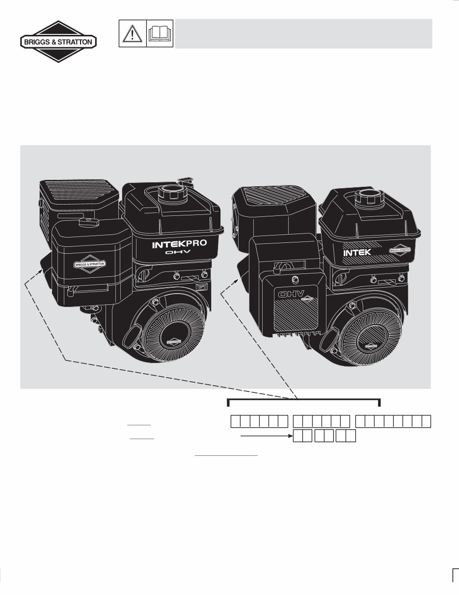
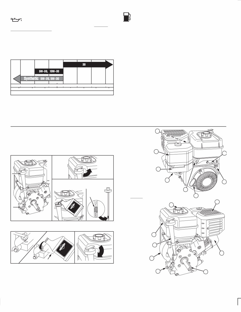
In the USA and Canada, a 24 hour hot line, 1-800-233-3723, has a menu of pre-recorded messages offering you engine maintenance information. 3 Oil & Fuel Recommendations Oil This engine is shipped from Briggs & Stratton without oil. Before starting engine , check oil level as shown below. Change and add oil according to chart below . Do not over-fill. Use a high quality detergent oil classified “For Service SF, SG, SH,” such as Briggs & Stratton “warranty certified” SAE 30 oil, Part No. 100005. Use no special additives with recommended oils. Do not mix oil with gasoline. SAE Viscosity Grades °C -30 STARTING TEMPERATURE RANGE ANTICIPATED BEFORE NEXT OIL CHANGE °F -20 0 20 40 60 80 100 -20 -10 0 10 20 30 40 * ** 32 * Air cooled engines run hotter than automotive engines. The use of multi-viscosity oil such as (10W-30, etc.) in ambient temperatures above 40 ° F (4° C) will result in higher than normal oil consumption. If multi-viscosity oil is used, check the oil level more frequently to prevent any possible engine damage due to lack of lubrication. ** Use of SAE 30 oil below 40° F (4° C) will result in hard starting and possible engine damage due to inadequate lubrication. Fuel Use clean, fresh, regular unleaded gasoline with a minimum of 85 octane. Do not mix oil with gasoline. Fresh fuel prevents gum from forming in fuel system or on essential carburetor parts. Purchase fuel in quantity that can be used within 30 days. In countries other than the U.S.A., leaded gasoline may be used if commercially available and unleaded is unavailable. We recommend the use of Briggs & Stratton Gasoline Additive. (See your Authorized Briggs & Stratton Service Dealer for Part No. 5041 or the single-use pouch.) See storage instruc- tions, on page 9. Note: Some fuels, called oxygenated or reformulated gasolines, are gasolines blended with alcohols or ethers. Excessive amounts of these blends can damage the fuel system or cause performance problems. Do not use gasoline which contains Methanol. If any undesirable operating symptoms occur, use gasoline with a lower percentage of alcohol or ether. Do not over-fill fuel tank. Allow space for fuel expansion. Check oil level before starting engine. Add oil as shown below. Engine oil capacity is about 20 ounces (5/8 quart or 0.6 liter). After filling with or changing oil, start and run engine at idle for 30 seconds. Shut engine off. Wait 30 seconds and check oil level. Add oil, if required, to bring level to Full mark on dipstick. Place engine level. Clean around oil fill. Pour oil slowly. Fill to FULL mark – recheck. Tighten oil filler plug or dipstick before starting engine. FULL If equipped with oil filler plug, remove plug and fill to overflowing. Remove dipstick. Wipe clean. Turn dipstick in 1/4 turn to check oil. OIL LEVEL 1. Spark plug wire 2. Air cleaner 3. Choke 4. Carburetor 5. Fuel shut-off valve 6. Rope handle 7. Stop switch/OIL GARD) light (if equipped) 8. Throttle 9. Engine Model Type Code xxxxxx xxxx xx xxxxxxxx 10. Muffler 11. Fuel fill 12. Fuel tank 13. Oil fill/Dipstick (if equipped) 14. Blower housing 15. Oil drain plug 16. Crankshaft 1 2 3 4 5 6 11 12 13 14 15 16 7 8 9 10
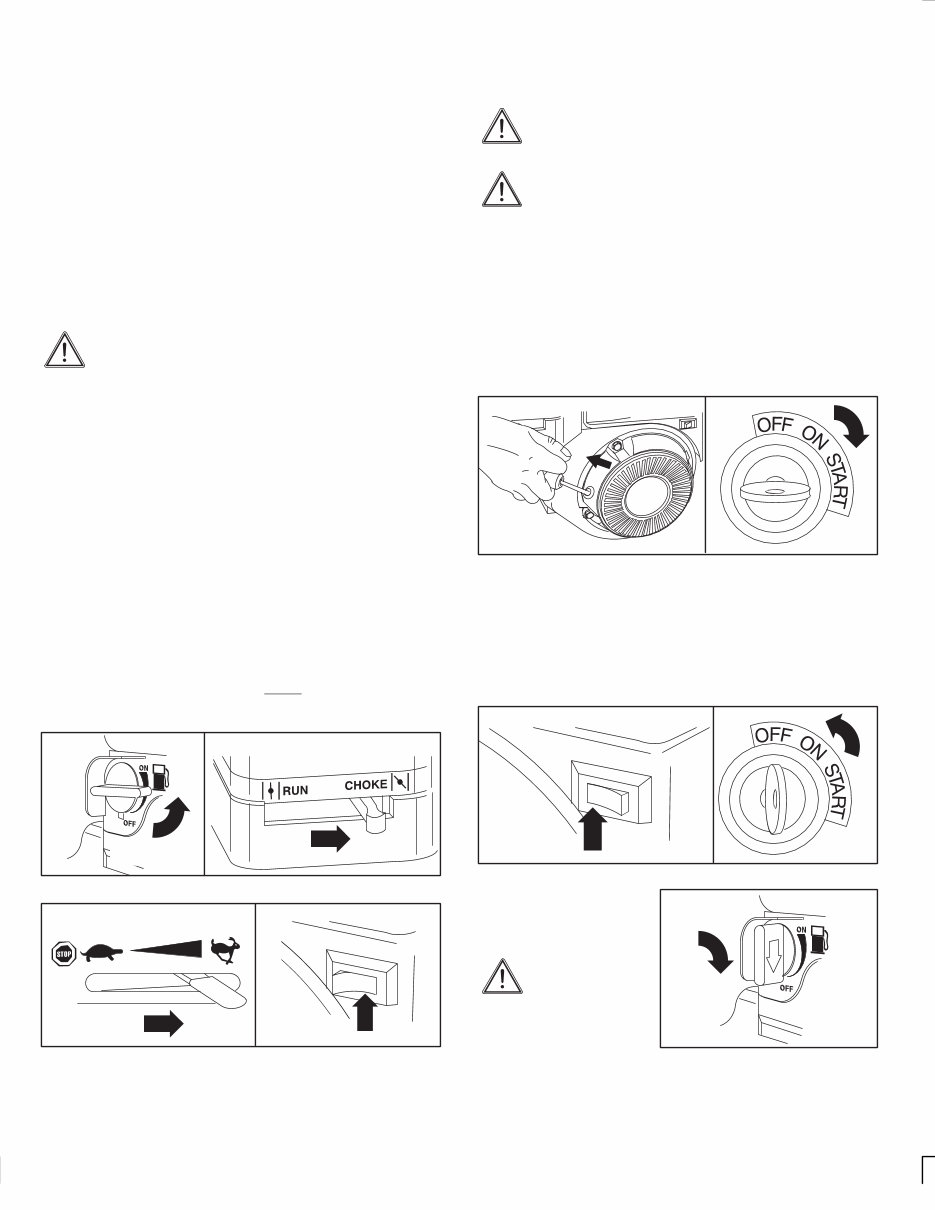
In the USA and Canada, a 24 hour hot line, 1-800-233-3723, has a menu of pre-recorded messages offering you engine maintenance information. 4 Starting & Stopping Choke operation/engine warm-up This engine is a low emissions engine which operates difer- ently from previously built engines. It is designed for maxi- mum performance and life if operated with the choke fully open (in RUN) and throttle fully open (in FAST). To open the choke fully requires an engine warm-up period of several seconds to several minutes, depending on the temperature. After starting engine, first open the choke (toward RUN) until the engine just begins to run smoothly. Then open the choke in small steps, allowing the engine to accept small changes in speed and load, until the choke is fully open (in RUN). During engine warm-up, the equipment can be operated. To obtain best starting results Start, store and fuel equipment with engine in level position. Do not use a pressurized starting fluid. Starting fluid is flammable. Severe engine damage or fire may occur . A warm engine requires less choking than a cold engine. Starting in cold weather: Use the correct oil for the starting temperature expected. De-clutch all possible external loads. A warm battery has more starting capacity than a cold battery . Do not use gasoline left over from summer. Use fresh winter grade gasoline which has higher volatility to improve starting. Before starting engine Turn fuel shut-off valve 1/4 turn to OPEN position. Move choke control to CHOKE position. Move throttle control to FAST position. Push rocker stop switch to ON position, if equipped. OIL GARD) light in rocker stop switch, if equipped, warns of low oil level. Light will flicker and engine will not start, or restart. Oil must be added. Fill to FULL mark on dipstick. Do not over-fill. OIL GARD ) , however, will not stop a running engine if the engine runs low on oil. Choke controls Fuel shut-off OPEN POSITION Stop switch Throttle control ON Start engine Always keep hands and feet clear of mower blade or other moving parts. Rewind starter Grasp rope handle as illustrated and pull slowly until resistance is felt. Then pull cord rapidly to overcome compression, prevent kickback and start engine. Repeat if necessary with choke off and throttle control in FAST position. Operate engine in FAST position. Electric starter , if equipped Turn key to START. Repeat if necessary with choke off and throttle control in FAST. Operate engine with choke in RUN and throttle in FAST position. Note: If equipment manufacturer has supplied battery, charge it before trying to start engine, as equipment manufacturer recom- mends. Use short starting cycles (15 secs. per min.) to prolong starter life. Extended cranking can damage starter motor. Rewind starter Typical electric starter switch Stop engine Do not move choke control to CHOKE position to stop engine. Backfire or engine damage may occur. Move throttle control to SLOW position, then to ST OP, or turn key to OFF , if equipped. Always remove key from switch when equipment is not in use or left unattended. Typical stop switches OFF Fuel shut-off valve CLOSED POSITION Turn fuel shut-off valve 1/4 turn to CLOSED position. Close fuel shut-of f valve, when transporting engine, to prevent fuel leakage.
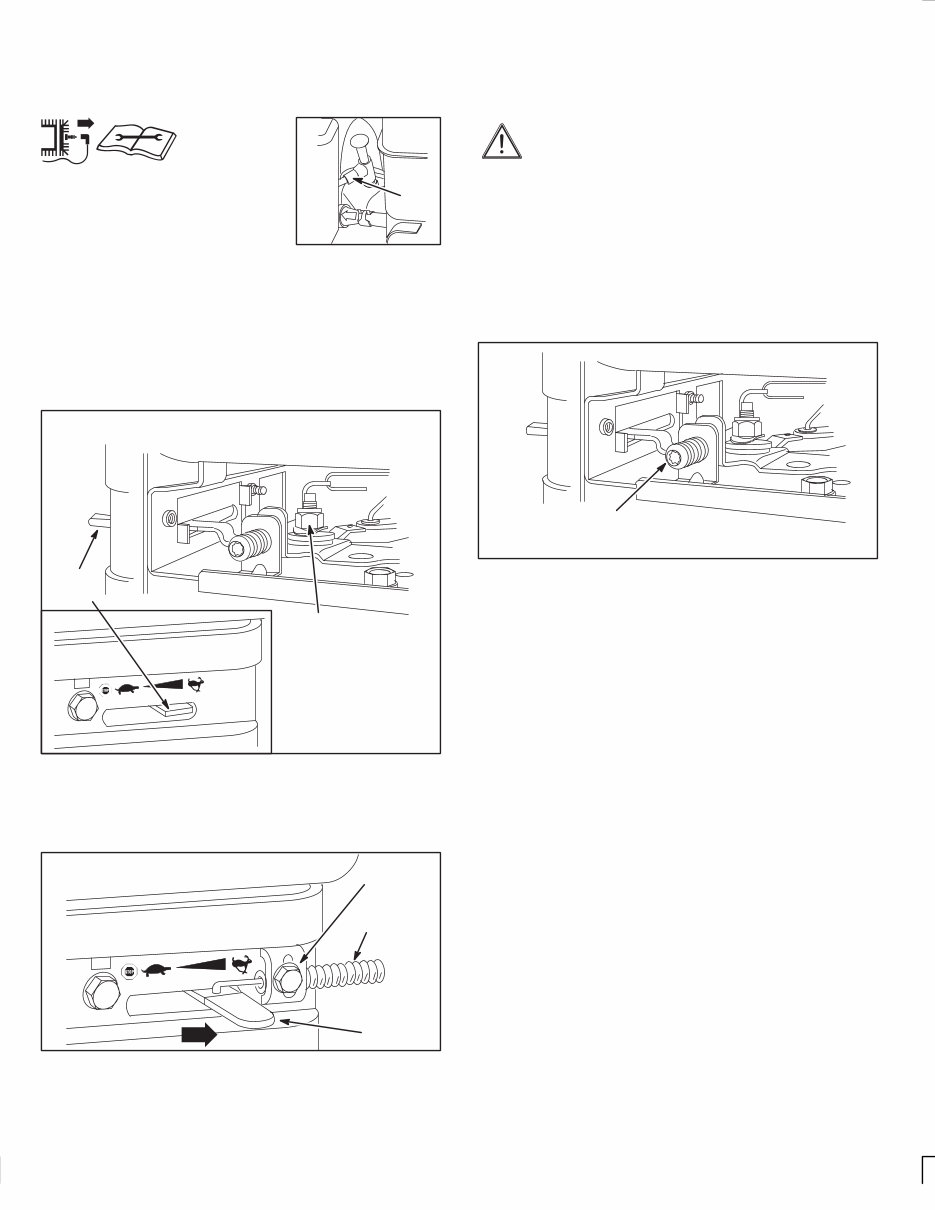
In the USA and Canada, a 24 hour hot line, 1-800-233-3723, has a menu of pre-recorded messages offering you engine maintenance information. 5 Adjustments Control adjustments To prevent accidental starting, remove spark plug wire from spark plug a nd disconnect battery at negative termi- nal, if equipped with electric starter , when adjusting controls. WIRE Manual choke control requires no adjustment. Manual friction control: If adjustment is required, loosen or tighten lock nut (illustrated below) until governor control lever moves easily, but stays in set position when engine is running. Fixed adjustable control: If adjustment is required, loosen lock nut. Move Governor control lever (inset) to FAST position. Tighten lock nut. 7/16” HEX LOCK NUT FUEL TANK REMOVE SIDE PANEL (IF EQUIPPED) GOVERNOR CONTROL LEVER Manual friction and fixed adjustable controls Remote control: Loosen casing clamp screw. Move casing, wire and lever in direction of arrow to end of travel. Move equipment throttle control to FAST position. Tighten casing clamp screw. Remote control GOVERNOR CONTROL LEVER FUEL TANK CASING CLAMP SCREW CASING AND WIRE Carburetor adjustments The manufacturer of equipment on which this engine is installed specifies top speed at which engine will be operated. DO NOT EXCEED this speed. Differences in fuel, temperature, altitude or load may require minor carburetor adjustment. Air cleaner and air cleaner cover must be assembled to carburetor before starting engine. The carburetor on this engine is low emission. It isequipped with a non-adjustable idle mixture valve and governed idle. Governed idle and top speed have been set at the factory. If adjustment is required, see an Authorized Briggs & Stratton Service Dealer. DO NOT ADJUST TOP SPEED SCREW. TOP SPEED SCREW FUEL TANK PARTS REMOVED FOR CLARITY
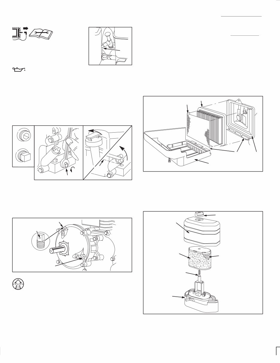
In the USA and Canada, a 24 hour hot line, 1-800-233-3723, has a menu of pre-recorded messages offering you engine maintenance information. 6 Maintenance See Maintenance Schedule, page 8. Follow the hourly or calendar intervals, whichever occur first . Note that more frequent service is required when operating in adverse conditions. To prevent accidental starting, remove spark plug wire and discon- nect battery at negative terminal, if equipped with electric starter , when servicing engine or equipment. WIRE Oil Check oil level regularly. Be sure correct oil level is maintained. Check every 8 hours or daily, before starting engine. See check oil level on page 3. Change oil (follow Maintenance Schedule). Change oil after first 5 hours of operation. Remove drain plug and drain oil while engine is warm. Replace drain plug. Remove dipstick and refill with new oil of recommended grade (see chart, page 3). Start and run engine at idle for 30 seconds. Stop engine. Wait 30 seconds and re-check oil level. If required, add oil to bring level to FULL mark on dipstick. Do not over-fill. Oil fill Oil drain Typical drain plugs 1/4” HEX PIPE OIL DRAIN PLUG OIL LEVEL Gear reduction, if equipped Remove oil level plug and oil fill plug. Drain oil every 100 hours of operation or every season. To refill, pour SAE 30 oil into oil fill hole until it runs out level check hole. Replace both plugs. Oil fill plug has a vent hole and must be installed on top of gear case cover. Oil drain/oil fill OIL FILLER PLUG OIL LEVEL PLUG VENT HOLE Air cleaners Dual element air cleaners To service pre-cleaner, if equipped, wash in liquid detergent and water. Squeeze dry in a clean cloth and allow to dry thoroughly. DO NOT oil pre-cleaner. Replace if very dirty or damaged. To service cartridge, clean by tapping gently on a flat surface. DO NOT oil cartridge. Replace if very dirty or damaged. Note: Do not use petroleum solvents, e.g., kerosene, which will cause the cartridge to deteriorate. Do not use pressurized air to clean cartridge. Pressurized air can damage the cartridge. Rectangular dual element air cleaner 1. Loosen screw and tilt cover down. Remove pre-cleaner (if equipped) and cartridge assembly from cover. 2. After servicing pre-cleaner and cartridge, place pre-cleaner with arrows up (if equipped) over cartridge pleats (pre-cleaner lip will be at bottom of pleats). 3. Install pre-cleaner and cartridge assembly in cover. 4. Insert tabs on cover into slots in bottom of base. 5. Tilt cover up and tighten screw securely. Square dual element air cleaner COVER PRE-CLEANER CARTRIDGE BASE SLOTS AND TABS Oval dual element air cleaner 1. Remove knob and cover. Lift air cleaner assembly off stud. 2. After cleaning, reassemble pre-cleaner on cartridge and push assembly firmly down on stud to seat in base. 3. Push cover squarely onto base. Tighten knob securely. Oval dual element air cleaner COVER PRE-CLEANER STUD CARTRIDGE BASE COVER KNOB
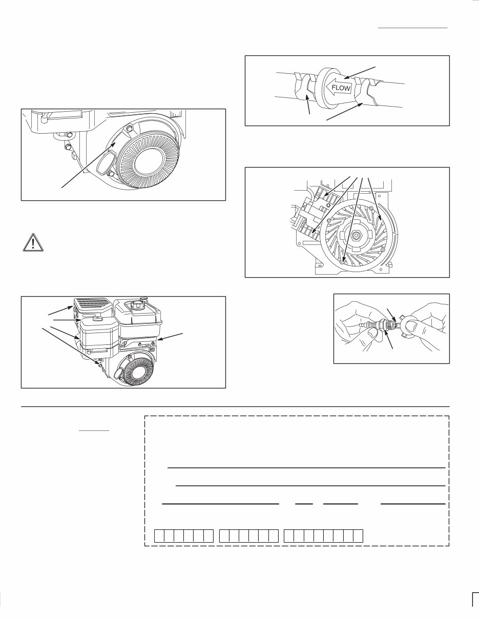
In the USA and Canada, a 24 hour hot line, 1-800-233-3723, has a menu of pre-recorded messages offering you engine maintenance information. 7 Maintenance See Maintenance Schedule, page 8. Follow the hourly or calendar intervals, whichever occur first . Note that more frequent service is required when operating in adverse conditions. Keep engine clean Remove dirt and debris with a cloth or brush. Do not clean with a forceful spray of water because water could contami- nate fuel system. Remove grass, chaff and dirt from finger guard daily (more often if needed) to prevent engine damage caused by overheating. Finger guard FINGER GUARD To assure smooth operation, keep governor linkage, springs and controls free of debris. Daily or more often, before running engine, clean muf- fler area to remove all grass and combustible debris. If engine muf fler is equipped with spark arrester screen, remove for cleaning and inspection. Replace if damaged or plugged. See an Authorized Briggs & Stratton Service Dealer for correct replacement. Linkage, springs, controls, muffler and spark arrester CLEAN CLEAN Clean fuel filter, if equipped, every 50 hours. Fuel filter FILTER CLAMPS Debris may clog the engine’ s air cooling system. Remove blower housing and clean area shown to prevent overheating and engine damage. Air cooling system CLEAN .030” (0.76 mm) WIRE GAGE RESISTOR P/N 802592 STANDARD P/N 492167 Spark plug Use only Briggs & Strat- ton Spark Tester, Part No. 19368, to check for spark. Replace or clean spark plug. D o n ot b last c lean. Clean by scraping or wire brushing and washing with a commercial solvent. Note: In some areas, local law requires using resistor spark plug to suppress ignition signals. If this engine was originally equipped with resistor spark plug, use same type for replacement. Name Address City State Zip County Fill in both sides, clip and return to: Briggs & Stratton Corporation P.O. Box 1144 Milwaukee, WI 53201-1144 U.S.A. Your Engine Type Code Model 273700 See any Authorized Briggs & Stratton Service Dealer . Insist on Genuine Briggs & Stratton parts! Non-original parts may not perform as well and may void your warranty. To obtain a complete Parts List of Genuine Briggs & Stratton Parts for your engine, fill in both sides of this order f orm c arefully. W e cannot fill your order without the correct Engine Model/T ype/Code. (Please allow 3 to 4 weeks for delivery.)
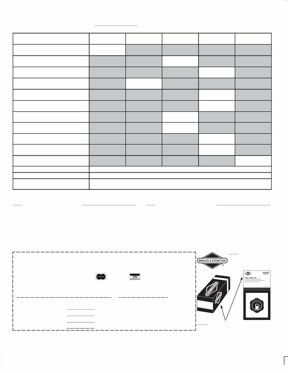
Maintenance Schedule Follow the hourly or calendar intervals, whichever occur first . More frequent service is required when operating in adverse conditions noted below. Only Genuine Briggs & Stratton Parts have the Briggs & Stratton logo! Look for Briggs & Stratton logo stamped on part and/or package! 273700 Payment Method: j Check or money order enclosed payable to Briggs & Stratton Corporation in the amount of $________ j Please charge my j MasterCard j VISA __ __ __ __ __ __ __ __ __ __ __ __ __ __ __ __ CREDIT CARD NUMBER SIGNATURE (REQUIRED FOR CREDIT CARD ORDERS EXPIRATION DATE Parts List $2.00 Shipping & Handling $1.50 **Add State Sales Tax Total Fill in both sides of this order form carefully (U.S. Dollars, please) Briggs & Stratton Part Numbers of some Genuine Briggs & Stratton Parts: Part Briggs & Stratton Part No. Oval air cleaner cartridge 498596 . . . . . . . . . . . . . . . . . . . . . . Oval air cleaner pre-cleaner 273356 . . . . . . . . . . . . . . . . . . . Square air cleaner cartridge 491588 . . . . . . . . . . . . . . . . . . . Square air cleaner pre-cleaner 493537 . . . . . . . . . . . . . . . . . Oil Foam) air cleaner 273332 . . . . . . . . . . . . . . . . . . . . . . . . Resistor spark plug 491055 . . . . . . . . . . . . . . . . . . . . . . . . . . . Spark tester 19368 . . . . . . . . . . . . . . . . . . . . . . . . . . . . . . . . . . . Fuel filter 499638 . . . . . . . . . . . . . . . . . . . . . . . . . . . . . . . . . . . . Briggs & Stratton Part Numbers of some Genuine Briggs & Stratton Parts: Part Briggs & Stratton Part No. Oil 100005 or 100028 . . . . . . . . . . . . . . . . . . . . . . . . . . . . . . . . . Gas additive 5041 . . . . . . . . . . . . . . . . . . . . . . . . . . . . . . . . . . . . Add sales tax if you live in any of the following states: **AL 5%, CT 6%, FL 6.5%, GA 4%, KY 6%, MI 6%, MN 6%, MO 4.225%, NY 8.5%, OH 5%, TN 6%, TX 6.25%, WA 6.5%,ĂWI 5% In the USA and Canada, a 24 hour hot line, 1-800-233-3723, has a menu of pre-recorded messages offering you engine maintenance information. 8 Maintenance Operation Every 8 Hours or Daily 25 Hours or Every Season 50 Hours or Every Season 100 Hours or Every Season Yearly Check oil level D Change oil ♦ D Note 1 Change oil gear reduction, if equipped D Service air cleaner pre-cleaner D Note 2 Service air cleaner cartridge D Note 2 Service Oil Foam) air cleaner D Note 2 Clean fuel filter, if equipped D Inspect spark arrester, if equipped D Replace spark plug D Clean cooling system D Note 2 Check valve clearance D ♦ Change oil after first 5 hours, then after every 50 hours or every season. Note 1: Change oil every 25 hours when operating under heavy load or in high temperatures. Note 2: Clean more often under dusty conditions or when airborne debris is present. Replace air cleaner parts, if very dirty.
In the USA and Canada, a 24 hour hot line, 1-800-233-3723, has a menu of pre-recorded messages offering you engine maintenance information. 9 Service, Storage & Specifications For service See an Authorized Briggs & Stratton Service Dealer . Each one carries a stock of Genuine Briggs & Stratton Parts and is equipped with special service tools. T rained mechanics assure expert repair service on all Briggs & Stratton engines. Only dealers advertising as “Authorized Briggs & Stratton” are required to meet Briggs & Stratton standards. When you purchase equipment powered by a Briggs & Stratton engine, you are assured of highly skilled, reliable service at more than 30,000 Authorized Service Dealersworldwide, including more than 2,700 Master Service Technicians. Look for these signs wherever Briggs & Stratton service is offered. You may locate your nearest Authorized Briggs & Stratton Service Dealer in o ur d ealer locator map on our web site www.briggsandstratton.com or in the “Y ellow Pages” directory under “Engines, Gasoline” or “Gasoline Engines,” or “Lawn Mowers” or similar category. Note: Walking fingers logo and “Yellow Pages” are registered trademarks in various jurisdictions. The illustrated shop manual shown here includes common specifications and de- tailed information covering adjustment, tune-up and repair of Briggs & Stratton Intek single cylinder , overhead valve, 4 cycle engines. It is available from an Authorized Briggs & Stratton Service Dealer or you can order it from the factory . Write: Briggs & Stratton Corporation Attn: Service Division P. O. Box 1144 Milwaukee, WI 53201 Part No. 274008 Storage instructions Engines stored over 30 days need to be protected or drained of fuel to prevent gum from forming in fuel system or on essential carburetor parts. 1. For engine protection, we recommend use of Briggs & Stratton Gasoline Additive, Part No. 5041, available from an Authorized Briggs & Stratton Service Dealer . Mix Additive with fuel in fuel tank or storage container . Run engine for a short time to circulate Additive through carburetor. Engine and fuel can be stored up to 24 months. P/N 5041 Your Service Dealer has single-use pouches of Gasoline Additive available. Note: If engine is operating on oxygenated or reformulated gasoline (gasoline blended with an alcohol or an ether), remove all fuel from tank and run engine until it stops from lack of fuel. If engine is stored with gasoline in fuel tank, we recommend the use of Gasoline additive, Part No. 5041. 2. While engine is still warm, drain oil from crankcase (see page 6). Refill with fresh oil of recommended grade (see chart page 3). 3. Remove spark plug and pour about 1/2 oz (15 ml) of engine oil into cylinder . Replace spark plug and crank slowly to distribute oil. 4. Clean dirt and chaff from cylinder, cylinder head fins, blower housing, rotating screen and muffler area (see page 7). 5. Store in a clean and dry area, but NOT near a stove, furnace or water heater which uses a pilot light or any device that can create a spark. General information This is a single cylinder , overhead valve (OHV), air-cooled engine. On mobile equipment, this engine will operate satisfactorily at any angle at which operator and equipment can function safely. Model Series 110400, 111400, 113400 Bore 2-11/16 in. (68 mm) . . . . . . . . . . . . . . . . . . . . . . . . . . . . . . Stroke 2-3/64 in. (52 mm) . . . . . . . . . . . . . . . . . . . . . . . . . . . . . Displacement 11.58 cu. in. (190 cc) . . . . . . . . . . . . . . . . . . . . . Model Series 120400, 121400, 123400 Bore 2-11/16 in. (68 mm) . . . . . . . . . . . . . . . . . . . . . . . . . . . . . . Stroke 2-13/64 in. (56 mm) . . . . . . . . . . . . . . . . . . . . . . . . . . . . Displacement 12.48 cu. in. (206 cc) . . . . . . . . . . . . . . . . . . . . Tune-up specifications Armature air gap is .010-.014 in. (.25-.36 mm) Spark plug gap is .030 in. (.76 mm) Valve clearance is: Intake* .004-.006 in. (.10-.15 mm) . . . . . . . . . . . . . . . . . . . . . . Exhaust* .004-.006 in. (.10-.15 mm) . . . . . . . . . . . . . . . . . . . . * Check when engine is cold.
In the USA and Canada, a 24 hour hot line, 1-800-233-3723, has a menu of pre-recorded messages offering you engine maintenance information. 10 273700 Briggs & Stratton Corporation (B&S), the California Air Resources Board (CARB) and the United States Environmental Protection Agency (U.S. EPA) Emission Control System Warranty Statement (Owner’s Defect Warranty Rights and Obligations) In the interest of the environment, B&S engines that meet strict emis- sion requirements are labeled, “This engine conforms to 1995 - 1998 California emission regulations for ULGE engines and U.S. EP A Phase I regulations for small non-road engines.” EMISSION CONTROL WARRANTY COVERAGE IS APPLICABLE TO CERTIFIED ENGINES PURCHASED IN CALIFORNIA IN 1995 AND THEREAFTER, WHICH ARE USED IN CALIFORNIA, AND TO CER TIFIED MODEL YEAR 1997 AND LA TER ENGINES WHICH ARE PURCHASED AND USED ELSEWHERE IN THE UNITED STATES. California and United States Emission Control Defects Warranty Statement CARB, U.S. EPA and B&S are pleased to explain the Emission Con- trol System Warranty on your 1996 and later utility or lawn and gar- den equipment (ULGE) engine. In California, new ULGE engines produced on or after August 1, 1995 must be designed, built and equipped to meet the State’s stringent anti-smog standards. Else- where in the United States, new non-road, spark-ignition engines certified for model year 1997 and later , must meet similar standards set forth by the U.S. EP A. B&S must warrant the emission control system on your engine for the periods of time listed below , provided there has been no abuse, neglect or improper maintenance of your ULGE engine. Your emission control system includes parts such as the carburetor , air cleaner, ignition system, muffler and catalytic converter. Also in- cluded may be connectors and other emission related assemblies. Where a warrantable condition exists, B&S will repair your ULGE en- gine at no cost to you including diagnosis, parts and labor. Briggs & Stratton Emission Control Defects Warranty Coverage ULGE engines are warranted relative to emission control parts de- fects for a period of two years, subject to provisions set forth below . If any covered part on your engine is defective, the part will be repaired or replaced by B&S. Owner’s Warranty Responsibilities As the ULGE engine owner , you are responsible for the performance of the required maintenance listed in your Operator/Owner Manual. B&S recommends that you retain all your receipts covering mainte- nance on your ULGE engine, but B&S cannot deny warranty solely for the lack of receipts or for your failure to ensure the performance of all scheduled maintenance. As the ULGE engine owner, you should however be aware that B&S may deny you warranty coverage if your ULGE engine or a part has failed due to abuse, neglect, improper maintenance or unapproved modifications. You are responsible for presenting your ULGE engine to an Autho- rized B&S Service Dealer as soon as a problem exists. The undis- puted warranty repairs should be completed in a reasonable amount of time, not to exceed 30 days. If you have any questions regarding your warranty rights and re- sponsibilities, you should contact a B&S Service Representative at 1-414-259-5262. The emission warranty is a defects warranty . Defects are judged on normal engine performance. The warranty is not related to an in-use emission test. Briggs & Stratton Emission Control Defects Warranty Provisions The following are specific provisions relative to your Emission Control Defects W arranty Coverage. It is in addition to the B&S engine warranty for non-regulated engines found in the Operator/Owner Manual. 1. Warranted Parts Coverage under this warranty extends only to the parts listed be- low (the emission control systems parts) to the extent these parts were present on the engine purchased. a. Fuel Metering System • Cold start enrichment system (soft choke) • Carburetor and internal parts • Fuel Pump b. Air Induction System • Air cleaner • Intake manifold c. Ignition System • Spark plug(s) • Magneto ignition system d. Catalyst System • Catalytic converter • Exhaust manifold • Air injection system or pulse valve e. Miscellaneous Items Used in Above Systems • Vacuum, temperature, position, time sensitive valves and switches • Connectors and assemblies 2. Length of Coverage B&S warrants to the initial owner and each subsequent purchaser that the Warranted Parts shall be free from defects in materials and workmanship which caused the failure of the W arranted Parts for a period of two years from the date the engine is deliv- ered to a retail purchaser. 3. No Charge Repair or replacement of any Warranted Part will be performed at no charge to the owner , including diagnostic labor which leads to the determination that a W arranted Part is defective, if the diagnostic work is performed at an Authorized B&S Service Dealer. For emissions warranty service contact your nearest Au- thorized B&S Service Dealer as listed in the “Yellow Pages” un- der “Engines, Gasoline,” “Gasoline Engines,” “Lawn Mowers,” or similar category. 4. Claims and Coverage Exclusions Warranty claims shall be filed in accordance with the provisions of the B&S Engine Warranty Policy. Warranty coverage shall be excluded for failures of Warranted Parts which are not original B&S parts or because of abuse, neglect or improper mainte- nance as set forth in the B&S Engine W arranty Policy. B&S is not liable to cover failures of Warranted Parts caused by the use of add-on, non-original, or modified parts. 5. Maintenance Any Warranted Part which is not scheduled for replacement as required maintenance or which is scheduled only for regular in- spection to the effect of “repair or replace as necessary” shall be warranted as to defects for the warranty period. Any Warranted Part which is scheduled for replacement as required mainte- nance shall be warranted as to defects only for the period of time up to the first scheduled replacement for that part. Any replace- ment part that is equivalent in performance and durability may be used in the performance of any maintenance or repairs. The owner is responsible for the performance of all required mainte- nance, as defined in the B&S Operator/Owner Manual. 6. Consequential Coverage Coverage hereunder shall extend to the failure of any engine components caused by the failure of any W arranted Part still un- der warranty.
The Intek Series Engine Operating Manual is designed for the 110400, 111000, 113400, 120400, 121400, and 123400 models. These engines are well-regarded for their reliable design, simple construction, and ease of repair, making them suitable for both professional mechanics and DIY enthusiasts.
Regular maintenance is crucial for these engines, with scheduled maintenance recommended every 8, 25, 50, 100 hours, or annually. This includes tasks such as oil changes, muffler inspections, spark plug replacements, and fuel and air filter replacements. A comprehensive service manual tailored to your specific engine model is invaluable for identifying motor parts and guiding you through routine maintenance.
Performing routine maintenance at home offers several advantages, including cost-effectiveness, prolonged engine lifespan, and a deeper understanding of engine components. Additionally, having familiarity with the engine's mechanics through regular maintenance can simplify any necessary repairs.
In the event of periodic repairs, access to service manuals and parts catalogues is highly beneficial. With the existing maintenance manual used for routine upkeep, having a parts catalogue on hand can streamline any required repairs.
This 12-page manual is available in a printable format, allowing users to access specific sections as needed. The contents cover a range of essential topics, including engine components, fuel, oil, choke operation, starting and stopping procedures, maintenance guidelines, and storage recommendations.