

BMW N55 Engine TRAINING Manual
What's Included?
Fast Download Speeds
Online & Offline Access
Access PDF Contents & Bookmarks
Full Search Facility
Print one or all pages of your manual

Revision Date:
N55 Engine
Introduction ..................................................5
Engine Components/Systems Overview ...........................6
Technical Data .................................................8
Full Load Diagram ............................................9
Current Models ...............................................10
Engine Designation and Engine Identification .....................11
Engine Designation .........................................11
Breakdown of N55 Engine Designation ........................12
Engine Identification ........................................12
Engine Components .........................................14
Engine Housing ...............................................14
Engine Block ...............................................14
Crankcase and Bedplate .....................................14
Crankshaft ....................................................17
Crankshaft Main Bearings .................................17
Pistons and Rings .............................................18
Connecting Rod and Bearings ..................................19
Oil Pan .......................................................22
Electrionic Volume-controlled Oil Pump ..........................23
Oil Pump and Pressure Control ...............................24
Oil Supply ....................................................27
Oil Filtration and Oil Cooling ..................................30
Oil Spray Nozzles ...........................................31
Oil Pressure ................................................31
Oil Level ...................................................31
Oil Return ..................................................31
Cylinder Head .................................................32
Cylinder Head Cover ........................................33
Crankcase Ventilation ..........................................34
Naturally Aspirated Mode ....................................34
Boost Mode ................................................36
Valvetrain .....................................................39
Intake and Exhaust Valves ....................................40
Valve Springs ...............................................40
Subject Page
Table of Contents
Initial Print Date: 02/10

Camshafts ....................................................41
Valve Timing ...............................................42
VANOS System ...............................................43
Overview ...................................................44
VANOS Solenoid Valves .....................................45
Cam Sensor Wheels ........................................45
Valvetronic III ..................................................46
Phasing ....................................................46
Masking ...................................................46
Combustion Chamber Geometry .............................49
Valve Lift Adjustment Overview ...............................50
Valvetronic Servomotor ...................................52
Function .................................................52
Belt Drive and Auxiliarly Components ............................53
Vibration Damper ..............................................54
Air Intake and Exhaust System ..................................56
Air Intake System ...........................................56
Intake Manifold .............................................59
Fuel Tank Ventilation System .................................60
Exhaust Manifold ...........................................61
Turbocharger ...............................................62
Function of the twin scroll turbocharger ....................65
Diverter valve ............................................65
Catalytic Converter ..........................................66
Exhaust System ............................................67
Vacuum System ...............................................68
Vacuum Pump ..............................................69
Fuel Injection .................................................71
Fuel Pressure Sensor .......................................72
High Pressure Fuel Pump ....................................73
Fuel Injectors ...............................................74
Cooling System ...............................................75
Components ...............................................77
N55, Cooling System Components ...........................77
Oil Cooler ...............................................79
Coolant Passages ...........................................80
Engine Electrical System .....................................82
Circuit Diagram ................................................83
Engine Cooling Circuit Diagram ...............................85
Digital Motor Electronics (DME/ECM) ............................87
Digital Motor Electronics Circuit Diagram ......................88
N55, MEVD17.2 Circuit Diagram .............................88
Functions ..................................................90
Subject Page

Fuel supply system ......................................90
Fuel quantity control .....................................90
Boost pressure control ...................................90
Engine cooling ..........................................91
System Protection .......................................92
Crankshaft Sensor ..........................................92
Ignition Coil ................................................94
Oil Pressure Sensor .........................................95
Oxygen Sensors ............................................95
Oxygen sensor before catalytic converter ...................96
Oxygen sensor after catalytic converter .....................96
Hot-film air mass meter ...................................97
High Pressure Fuel Injector Valve .............................97
Function .................................................98
Service Information ..........................................99
Cylinder Head .................................................99
Cylinder Head Cover ...........................................99
Fuel Injectors .................................................99
Ignition Coils .................................................100
Subject Page

N55 Engine
Model: All with N55
Production: From Start of Production
After completion of this module you will be able to:
• Describe the features of the N55B30M0 engine
• Describe the specifications of the N55 engine
• Identify the internal and external components of the N55 engine
• Understand the function of the crankcase ventilation on the N55 engine
• Understand the function of the electronic volume control oil pump
4
N55 Engine

The N55 engine is the successor to the N54. Re-engineering and modifications have
made it possible to now use only one exhaust turbocharger. Against the backdrop of
reduced costs and improved quality, the technical data have remained virtuallythe same.
N55 Engine
Introduction
5
N55 Engine

Engine Components/Systems Overview
The following provides an overview of the features of the N55 engine:
Crankcase:
• Large longitudinal ventilation holes inter-connect the crankcase lower chambers
and relieve unwanted crankcase pressure between cylinders.
• Modified oil galleries enhance the supply of oil to vacuum pump.
Crankshaft: Is light weight design and has an asymmetric counterweight arrangement.
Pistons and connecting rods:
• A specially formed bushing/bore in small end of the connecting rods evenly
distributes the force of the pistons on the power stroke.
• Lead-free bearing shells are installed on the big-end of the connecting rods.
Cylinder head:
• Specially designed water passages intergraded into the cylinder head enhance
injector cooling.
• The combustion chambers are machined to work in conjuction with the Valvetronic
III system with regard to promoting air turbulence and mixture formation.
Crankcase ventilation:
• In contrast to the N54, the N55 crankcase ventilation does not use cyclone
separators.
• The cylinder and head cover have integrated blow-by passages that connect the
crankcase ventilation directly to the intake ports.
VANOS:
• The N55 VANOS oil passages are simplified compared to the N54 engine.
• The solenoid valves have integrated non-return valve and 3 screen filters.
• The VANOS units are of a lightweight design for increased adjustment speed
and have a reduced susceptibility to soiling.
Valvetrain:
• The N55 is the first BMW turbo engine to incorporate Valvetronic.
• The valvetrain is a new designed that combines Valvetronic III with Double VANOS.
• With Valvetronic III the 3rd generation brushless servomotor is introduced.
• The position detection sensor of eccentric shaft is now integrated in the servomotor.
6
N55 Engine

Oil supply:
• An enhanced and simplified oil circuit design is used.
• The inlet pipe, oil deflector, and oil collector are combined in one component.
• Oil pump uses a Duroplast slide valve and it is electronically controlled based on
a characteristic map within the engine management.
Forced induction:
• The N55 uses a single twin scroll turbocharger with vacuum operated,
electronically controlled wastegate valve.
• The electric diverter valve is intergraded into the turbocharger compressor housing.
Air intake and exhaust system:
• Air intake system is similar in configuration as the N54 with the exception of the
intake manifold and the use of a single turbo.
• The intercooler is an air to air type mounted in the lower area of the front bumper
cover.
• The exhaust system uses no underbody catalytic converter.
Vacuum system:
• The N55 engine has a two-stage vacuum pump as on the N54.
• The vacuum system has the vacuum reservoir built into the cylinder head cover.
Fuel injection:
• HDE (high pressure fuel injection) system is installed on the N55.
• The HDE system uses solenoid valve fuel injectors instead of the piezoelectric
type used on HPI.
• The high pressure pump and pressure sensors are similar in design and function
in both the HDE and HPI systems.
Digital Motor Electronics (DME):
• The DME is mounted on the intake manifold and cooled byintake air.
• The location of the DME facilitates the installation of the N55 engine in several
current BMW platforms/models.
7
N55 Engine

Technical Data
Unit
N54B30O0 (E71/X6
xDrive35i)
N55B30M0
(F07/535i)
Configuration 6 inline 6 inline
Cylinder capacity [cm³] 2979 2979
Bore/stroke [mm] 84.0/89.6 84.0/89.6
Power output at
engine speed
[kW/bhp] [rpm] 225/306 5800 - 6250 225/306 5800 - 6400
Power output per liter [kW/l] 75.53 75.53
Torque at engine speed [Nm] [rpm] 400 1300 - 5000 400 1200 - 5000
Compression ratio [ε] 10.2 10.2
Valves/cylinder 4 4
Fuel consumption,
EU combined
[l/100 km] 10.9 8.9
CO2 emission g/km 262 209
Digital Motor Electronics MSD81 MEVD17.2
Exhaust emission
legislation, US
ULEV ULEV II
Engine oil specification
BMW Longlife-01 BMW
Longlife-01 FE BMW
Longlife-04
-
Top speed [km/h] 240 250
Acceleration
0 - 100 km/h/62mph
[s] 6.7 6.3
Vehicle curb weight DIN/EU [kg] 2070/2145 1940/2015
* = Electronically governed
8
N55 Engine
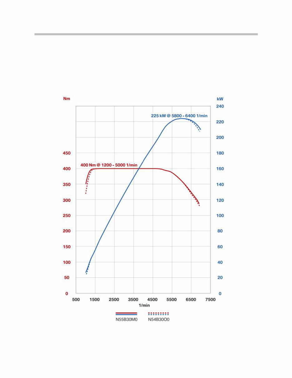
Full Load Diagram
Compared to its predecessor, the N55 engine is characterized by lowerfuel consumption
with the same power output and torque data.
Full load diagram E90 335i with N54B30O0 engine
compared to the F07 535i with N55B30M0 engine
9
N55 Engine

10
N55 Engine
Current Models
N54B30O0 engine variants
* The enhanced engine management system of the BMW Z4 sDrive35is and the 335is include
an electronically controlled overboost function to briefly increase torque under full load by
another 37 ft-lbs. This temporary torque peak of 369 ft-lbs gives the car a significant increase
in acceleration for approximately 5 seconds.
Model Version Series
Displace-
ment in
cm³
Stroke/
bore in
mm
Power
output in
kW/bhp at
rpm
Torque in
Nm at rpm
135i US E82, E88 2979 89.6/84.0
300 SAE hp
5800 - 6250
407
(300 ft-lbs)
1400 - 5000
335i US
E90, E92,
E93
2979 89.6/84.0
300 SAE hp
5800 - 6250
407
(300 ft-lbs)
1400 - 5000
335i xDrive US E90, E92 2979 89.6/84.0
300 SAE hp
5800 - 6250
407
(300 ft-lbs)
1400 - 5000
335is US E92, E93 2979 89.6/84.0
320 SAE hp
5800 - 6250
450
(332 ft-lbs)
1400 - 5000
Z4 sDrive35i US E89 2979 89.6/84.0
300 SAE hp
5800 - 6250
407
(300 ft-lbs)
1400 - 5000
Z4
sDrive35is
US E89 2979 89.6/84.0
335 SAE hp
5800 - 6250
450
(332/369 ft-lbs)
*1400 - 5000
535i US E60 2979 89.6/84.0
300 SAE hp
5800 - 6250
407
(300 ft-lbs)
1400 - 5000
535i xDrive US E60, E61 2979 89.6/84.0
300 SAE hp
5800 - 6250
407
(300 ft-lbs)
1400 - 5000
X6 xDrive35i US E71 2979 89.6/84.0
300 SAE hp
5800 - 6250
407
(300 ft-lbs)
1400 - 5000
740i US F01, F02 2979 89.6/84.0
315 SAE hp
5800 - 6250
450
(330 ft-lbs)
1600 - 4500
You're Reading a Preview
What's Included?
Fast Download Speeds
Online & Offline Access
Access PDF Contents & Bookmarks
Full Search Facility
Print one or all pages of your manual
$31.99
$41.99
Viewed 75 Times Today


Secure transaction
What's Included?
Fast Download Speeds
Online & Offline Access
Access PDF Contents & Bookmarks
Full Search Facility
Print one or all pages of your manual
$31.99
$41.99
These digital manuals provide comprehensive technical information and an overview of engine components and systems. They are valuable resources for both professional mechanics and DIY enthusiasts.
- Full Load Diagram
- Current Models
- Engine Designation and Engine Identification
- Engine Designation
- Breakdown of N55 Engine Designation
- Engine Identification
- Engine Components
- Engine Housing
- Engine Block
- Crankcase and Bedplate
- Crankshaft
- Crankshaft Main Bearings
- Pistons and Rings
- Connecting Rod and Bearings
- Oil Pan
- Electrionic Volume-controlled Oil Pump
- Oil Pump and Pressure Control
- Oil Supply
- Oil Filtration and Oil Cooling
- Oil Spray Nozzles
- Oil Pressure
- Oil Level
- Oil Return
- Cylinder Head
- Cylinder Head Cover
- Crankcase Ventilation
- Naturally Aspirated Mode
- Boost Mode
- Valvetrain
- Intake and Exhaust Valves
- Valve Springs
- Camshafts
- Valve Timing
- VANOS System
- Overview
- VANOS Solenoid Valves
- Cam Sensor Wheels
- Valvetronic III
- Phasing
- Masking
- Combustion Chamber Geometry
- Valve Lift Adjustment Overview
- Valvetronic Servomotor
- Belt Drive and Auxiliarly Components
- Vibration Damper
- Air Intake and Exhaust System
- Air Intake System
- Intake Manifold
- Fuel Tank Ventilation System
- Exhaust Manifold
- Turbocharger
- Function of the twin scroll turbocharger
- Diverter valve
- Catalytic Converter
- Exhaust System
- Vacuum System
- Vacuum Pump
- Fuel Injection
- Fuel Pressure Sensor
- High Pressure Fuel Pump
- Fuel Injectors
- Cooling System
- Components
- N55, Cooling System Components
- Oil Cooler
- Coolant Passages
- Engine Electrical System
- Circuit Diagram
- Engine Cooling Circuit Diagram
- Motor Electronics (DME/ECM)
- Motor Electronics Circuit Diagram
- N55, MEVD17.2 Circuit Diagram
- Functions
- Fuel supply system
- Fuel quantity control
- Boost pressure control
- Engine cooling
- System Protection
- Crankshaft Sensor
- Ignition Coil
- Oil Pressure Sensor
- Oxygen Sensors
- Oxygen sensor before catalytic converter
- Oxygen sensor after catalytic converter
- Hot-film air mass meter
- High Pressure Fuel Injector Valve
- Function
- Service Information
- Cylinder Head
- Cylinder Head Cover
- Fuel Injectors
- Ignition Coils
These manuals are essential for understanding the intricate details of engine components, systems, and their functionalities.


