

MTD REAR Engine RIDERS Lawn TractorS Service Manual
What's Included?
Fast Download Speeds
Online & Offline Access
Access PDF Contents & Bookmarks
Full Search Facility
Print one or all pages of your manual

MTD SERVICE LLC Product Training and Education Department
For Parts Call 606-678-9623 or 606-561-4983
www.mymowerparts.com

TABLE OF CONTENTS
WORK SAFETY . . . . . . . . . . . . . . . . . . . . . . . . . . . . . . . . . . . . . . . . . . . . . . . . . . . . . . . . . . . . . . . . . . Section 1
GENERAL INFORMATION . . . . . . . . . . . . . . . . . . . . . . . . . . . . . . . . . . . . . . . . . . . . . . . . . . . . . . . . . . Section 2
Safety Precautions . . . . . . . . . . . . . . . . . . . . . . . . . . . . . . . . . . . . . . . . . . . . . . . . . . . . . . . . . . . . . . . . . . . 2-1
Batteries And Charging Systems . . . . . . . . . . . . . . . . . . . . . . . . . . . . . . . . . . . . . . . . . . . . . . . . . . . . . . . . . 2-2
ELECTRICAL . . . . . . . . . . . . . . . . . . . . . . . . . . . . . . . . . . . . . . . . . . . . . . . . . . . . . . . . . . . . . . . . . . . . Section 3
Safety Interlock Systems . . . . . . . . . . . . . . . . . . . . . . . . . . . . . . . . . . . . . . . . . . . . . . . . . . . . . . . . . . . . . . . 3-1
Safety Interlock Systems - Changes for 1991 . . . . . . . . . . . . . . . . . . . . . . . . . . . . . . . . . . . . . . . . . . . . . . . 3-1
Electric Start System . . . . . . . . . . . . . . . . . . . . . . . . . . . . . . . . . . . . . . . . . . . . . . . . . . . . . . . . . . . . . . . . . . 3-3
Recoil Start System . . . . . . . . . . . . . . . . . . . . . . . . . . . . . . . . . . . . . . . . . . . . . . . . . . . . . . . . . . . . . . . . . . . 3-6
Safety Interlock Systems Wiring Diagrams . . . . . . . . . . . . . . . . . . . . . . . . . . . . . . . . . . . . . . . . . . . . . . . . 3-10
Troubleshooting Safety Interlock Systems . . . . . . . . . . . . . . . . . . . . . . . . . . . . . . . . . . . . . . . . . . . . . . . . 3-23
Evaluating Electric Clutches . . . . . . . . . . . . . . . . . . . . . . . . . . . . . . . . . . . . . . . . . . . . . . . . . . . . . . . . . . . 3-56
BELTS AND DRIVE SYSTEM . . . . . . . . . . . . . . . . . . . . . . . . . . . . . . . . . . . . . . . . . . . . . . . . . . . . . . . . Section 4
General . . . . . . . . . . . . . . . . . . . . . . . . . . . . . . . . . . . . . . . . . . . . . . . . . . . . . . . . . . . . . . . . . . . . . . . . . . . 4-1
Proper Storage of Belts . . . . . . . . . . . . . . . . . . . . . . . . . . . . . . . . . . . . . . . . . . . . . . . . . . . . . . . . . . . . . . . 4-3
Causes of V-Belt Problems . . . . . . . . . . . . . . . . . . . . . . . . . . . . . . . . . . . . . . . . . . . . . . . . . . . . . . . . . . . . . 4-3
V-Belt Problems with Rotary Tillers, Self-Propelled Mowers and Riding Mowers . . . . . . . . . . . . . . . . . . . . 4-4
Belt Wear Due to Normal Life . . . . . . . . . . . . . . . . . . . . . . . . . . . . . . . . . . . . . . . . . . . . . . . . . . . . . . . . . . . 4-5
Pulley Alignment . . . . . . . . . . . . . . . . . . . . . . . . . . . . . . . . . . . . . . . . . . . . . . . . . . . . . . . . . . . . . . . . . . . . . 4-6
Idlers . . . . . . . . . . . . . . . . . . . . . . . . . . . . . . . . . . . . . . . . . . . . . . . . . . . . . . . . . . . . . . . . . . . . . . . . . . . . . . 4-6
Maintenance Of Variable Speed Pulleys . . . . . . . . . . . . . . . . . . . . . . . . . . . . . . . . . . . . . . . . . . . . . . . . . . . 4-9
Four Wheel Steering . . . . . . . . . . . . . . . . . . . . . . . . . . . . . . . . . . . . . . . . . . . . . . . . . . . . . . . . . . . . . . . . . 4-10
Disassembly Of Four Wheel Steering . . . . . . . . . . . . . . . . . . . . . . . . . . . . . . . . . . . . . . . . . . . . . . . . . . . . 4-13
Brake Adjustment for 600 and 700 Series . . . . . . . . . . . . . . . . . . . . . . . . . . . . . . . . . . . . . . . . . . . . . . . . . 4-15
HYDROSTATIC . . . . . . . . . . . . . . . . . . . . . . . . . . . . . . . . . . . . . . . . . . . . . . . . . . . . . . . . . . . . . . . . . . . Section 5
TRANSAXLES . . . . . . . . . . . . . . . . . . . . . . . . . . . . . . . . . . . . . . . . . . . . . . . . . . . . . . . . . . . . . . . . . . . Section 6
General . . . . . . . . . . . . . . . . . . . . . . . . . . . . . . . . . . . . . . . . . . . . . . . . . . . . . . . . . . . . . . . . . . . . . . . . . . . . 6-1
Transaxle Changes For 1990, 1991, 1992 and 1997 Models . . . . . . . . . . . . . . . . . . . . . . . . . . . . . . . . . . . 6-3
Disassembly/Assembly of Transaxle . . . . . . . . . . . . . . . . . . . . . . . . . . . . . . . . . . . . . . . . . . . . . . . . . . . . . . 6-5
Hydrostatic Transaxle . . . . . . . . . . . . . . . . . . . . . . . . . . . . . . . . . . . . . . . . . . . . . . . . . . . . . . . . . . . . . . . . 6-13
Integrated Hydrostatic Transaxle . . . . . . . . . . . . . . . . . . . . . . . . . . . . . . . . . . . . . . . . . . . . . . . . . . . . . . . . 6-17
LAWN TRACTORS . . . . . . . . . . . . . . . . . . . . . . . . . . . . . . . . . . . . . . . . . . . . . . . . . . . . . . . . . . . . . . . . Section 7
300 and 400 Series . . . . . . . . . . . . . . . . . . . . . . . . . . . . . . . . . . . . . . . . . . . . . . . . . . . . . . . . . . . . . . . . . . . 7-1
Rear Engine Riding Mowers 500 Series . . . . . . . . . . . . . . . . . . . . . . . . . . . . . . . . . . . . . . . . . . . . . . . . . . . 7-6
Transmatic LT 600A. . . . . . . . . . . . . . . . . . . . . . . . . . . . . . . . . . . . . . . . . . . . . . . . . . . . . . . . . . . . . . . . . . . 7-9
Hydrostatic Drive 700 Series . . . . . . . . . . . . . . . . . . . . . . . . . . . . . . . . . . . . . . . . . . . . . . . . . . . . . . . . . . . 7-35
YARD BUG . . . . . . . . . . . . . . . . . . . . . . . . . . . . . . . . . . . . . . . . . . . . . . . . . . . . . . . . . . . . . . . . . . . . . . Section 8
Deck Leveling . . . . . . . . . . . . . . . . . . . . . . . . . . . . . . . . . . . . . . . . . . . . . . . . . . . . . . . . . . . . . . . . . . . . . . . 8-1
Brake Adjustment . . . . . . . . . . . . . . . . . . . . . . . . . . . . . . . . . . . . . . . . . . . . . . . . . . . . . . . . . . . . . . . . . . . . 8-3
Blade Brake/PTO Adjustment . . . . . . . . . . . . . . . . . . . . . . . . . . . . . . . . . . . . . . . . . . . . . . . . . . . . . . . . . . . 8-5
Speed Control Pedal Adjustment. . . . . . . . . . . . . . . . . . . . . . . . . . . . . . . . . . . . . . . . . . . . . . . . . . . . . . . . . 8-6
Steering Adjustment . . . . . . . . . . . . . . . . . . . . . . . . . . . . . . . . . . . . . . . . . . . . . . . . . . . . . . . . . . . . . . . . . . 8-9
Removal and Installation of Deck Belt . . . . . . . . . . . . . . . . . . . . . . . . . . . . . . . . . . . . . . . . . . . . . . . . . . . . 8-11
Removal and Installation of Mowing Deck Assembly . . . . . . . . . . . . . . . . . . . . . . . . . . . . . . . . . . . . . . . . 8-12
Removal and Replacement of the Drive Belts . . . . . . . . . . . . . . . . . . . . . . . . . . . . . . . . . . . . . . . . . . . . . . 8-14
Transmission Removal and Installation . . . . . . . . . . . . . . . . . . . . . . . . . . . . . . . . . . . . . . . . . . . . . . . . . . . 8-16
Transmission Disassembly . . . . . . . . . . . . . . . . . . . . . . . . . . . . . . . . . . . . . . . . . . . . . . . . . . . . . . . . . . . . 8-18
Transmission Reassembly. . . . . . . . . . . . . . . . . . . . . . . . . . . . . . . . . . . . . . . . . . . . . . . . . . . . . . . . . . . . . 8-20
Electrical . . . . . . . . . . . . . . . . . . . . . . . . . . . . . . . . . . . . . . . . . . . . . . . . . . . . . . . . . . . . . . . . . . . . . . . . . . 8-23
2
3
4
5
6
1
7
8
For Parts Call 606-678-9623 or 606-561-4983
www.mymowerparts.com

AUTO DRIVE . . . . . . . . . . . . . . . . . . . . . . . . . . . . . . . . . . . . . . . . . . . . . . . . . . . . . . . . . . . . . . . . . . . . . Section 9
Leveling the Cutting Deck . . . . . . . . . . . . . . . . . . . . . . . . . . . . . . . . . . . . . . . . . . . . . . . . . . . . . . . . . . . . . 9-1
Deck Belt Removal and Installation . . . . . . . . . . . . . . . . . . . . . . . . . . . . . . . . . . . . . . . . . . . . . . . . . . . . . . 9-3
Cutting Deck Removal . . . . . . . . . . . . . . . . . . . . . . . . . . . . . . . . . . . . . . . . . . . . . . . . . . . . . . . . . . . . . . . . . 9-4
Brake Adjustments. . . . . . . . . . . . . . . . . . . . . . . . . . . . . . . . . . . . . . . . . . . . . . . . . . . . . . . . . . . . . . . . . . . . 9-5
Autodrive Pedal Adjustment . . . . . . . . . . . . . . . . . . . . . . . . . . . . . . . . . . . . . . . . . . . . . . . . . . . . . . . . . . . . 9-5
Drive Belt Removal and Reinstallation . . . . . . . . . . . . . . . . . . . . . . . . . . . . . . . . . . . . . . . . . . . . . . . . . . . . 9-6
Transmission Removal and Installation . . . . . . . . . . . . . . . . . . . . . . . . . . . . . . . . . . . . . . . . . . . . . . . . . . . . 9-9
Transmission Disassembly and Reassembly . . . . . . . . . . . . . . . . . . . . . . . . . . . . . . . . . . . . . . . . . . . . . . 9-11
Deck Belt Removal . . . . . . . . . . . . . . . . . . . . . . . . . . . . . . . . . . . . . . . . . . . . . . . . . . . . . . . . . . . . . . . . . . 9-14
Hydrostatic Transmission Removal . . . . . . . . . . . . . . . . . . . . . . . . . . . . . . . . . . . . . . . . . . . . . . . . . . . . . . 9-16
Steering Adjustments. . . . . . . . . . . . . . . . . . . . . . . . . . . . . . . . . . . . . . . . . . . . . . . . . . . . . . . . . . . . . . . . . 9-20
Electrical . . . . . . . . . . . . . . . . . . . . . . . . . . . . . . . . . . . . . . . . . . . . . . . . . . . . . . . . . . . . . . . . . . . . . . . . . . 9-21
Autodrive/Autocruise . . . . . . . . . . . . . . . . . . . . . . . . . . . . . . . . . . . . . . . . . . . . . . . . . . . . . . . . . . . . . . . . . 9-30
MTD Z SERIES . . . . . . . . . . . . . . . . . . . . . . . . . . . . . . . . . . . . . . . . . . . . . . . . . . . . . . . . . . . . . . . . . . Section 10
Transmission . . . . . . . . . . . . . . . . . . . . . . . . . . . . . . . . . . . . . . . . . . . . . . . . . . . . . . . . . . . . . . . . . . . . . . . 10-1
Neutral/Steering Adjustment . . . . . . . . . . . . . . . . . . . . . . . . . . . . . . . . . . . . . . . . . . . . . . . . . . . . . . . . . . . 10-1
Removal of ZTT Transmission . . . . . . . . . . . . . . . . . . . . . . . . . . . . . . . . . . . . . . . . . . . . . . . . . . . . . . . . . 10-8
Transmission Disassembly . . . . . . . . . . . . . . . . . . . . . . . . . . . . . . . . . . . . . . . . . . . . . . . . . . . . . . . . . . . 10-13
ZERO TURN TRACTORS . . . . . . . . . . . . . . . . . . . . . . . . . . . . . . . . . . . . . . . . . . . . . . . . . . . . . . . . . . .Section 11
624 Zero Turn Tractor - The Revolution . . . . . . . . . . . . . . . . . . . . . . . . . . . . . . . . . . . . . . . . . . . . . . . . . . 11-1
46" Cutting Deck . . . . . . . . . . . . . . . . . . . . . . . . . . . . . . . . . . . . . . . . . . . . . . . . . . . . . . . . . . . . . . . . . . . . 11-2
Cutting Deck Removal . . . . . . . . . . . . . . . . . . . . . . . . . . . . . . . . . . . . . . . . . . . . . . . . . . . . . . . . . . . . . . . 11-2
Lower Deck Belt Removal . . . . . . . . . . . . . . . . . . . . . . . . . . . . . . . . . . . . . . . . . . . . . . . . . . . . . . . . . . . . . 11-3
Servicing the IZT Drive Belt . . . . . . . . . . . . . . . . . . . . . . . . . . . . . . . . . . . . . . . . . . . . . . . . . . . . . . . . . . . . 11-3
Servicing the IZT . . . . . . . . . . . . . . . . . . . . . . . . . . . . . . . . . . . . . . . . . . . . . . . . . . . . . . . . . . . . . . . . . . . . 11-7
Adjustments to the IZT . . . . . . . . . . . . . . . . . . . . . . . . . . . . . . . . . . . . . . . . . . . . . . . . . . . . . . . . . . . . . . . 11-9
Parking Brake . . . . . . . . . . . . . . . . . . . . . . . . . . . . . . . . . . . . . . . . . . . . . . . . . . . . . . . . . . . . . . . . . . . . . 11-10
Under Dash Service Points1 . . . . . . . . . . . . . . . . . . . . . . . . . . . . . . . . . . . . . . . . . . . . . . . . . . . . . . . . . . 11-11
Dash Panel Removal . . . . . . . . . . . . . . . . . . . . . . . . . . . . . . . . . . . . . . . . . . . . . . . . . . . . . . . . . . . . . . . . 11-12
Front Axle . . . . . . . . . . . . . . . . . . . . . . . . . . . . . . . . . . . . . . . . . . . . . . . . . . . . . . . . . . . . . . . . . . . . . . . . 11-16
ATTACHMENTS . . . . . . . . . . . . . . . . . . . . . . . . . . . . . . . . . . . . . . . . . . . . . . . . . . . . . . . . . . . . . . . . . Section 12
Cutting Decks . . . . . . . . . . . . . . . . . . . . . . . . . . . . . . . . . . . . . . . . . . . . . . . . . . . . . . . . . . . . . . . . . . . . . . 12-3
Improvements . . . . . . . . . . . . . . . . . . . . . . . . . . . . . . . . . . . . . . . . . . . . . . . . . . . . . . . . . . . . . . . . . . . . . 12-22
Grass Collectors. . . . . . . . . . . . . . . . . . . . . . . . . . . . . . . . . . . . . . . . . . . . . . . . . . . . . . . . . . . . . . . . . . . . 12-37
Front Bumper. . . . . . . . . . . . . . . . . . . . . . . . . . . . . . . . . . . . . . . . . . . . . . . . . . . . . . . . . . . . . . . . . . . . . . 12-39
Trapac . . . . . . . . . . . . . . . . . . . . . . . . . . . . . . . . . . . . . . . . . . . . . . . . . . . . . . . . . . . . . . . . . . . . . . . . . . . 12-39
42" Dozer Blade . . . . . . . . . . . . . . . . . . . . . . . . . . . . . . . . . . . . . . . . . . . . . . . . . . . . . . . . . . . . . . . . . . . 12-40
GLOSSARY
9
10
11
12
Glossary
For Parts Call 606-678-9623 or 606-561-4983
www.mymowerparts.com

1-1
1
1. To prevent accidental starting, always pull the
high tension wire(s) off the spark plug(s) before
servicing and/or adjusting the machine.
2. To prevent injury, do not allow children or
bystanders around the machine while it is
being adjusted and/or serviced.
3. Do not wear rings, wrist watches or loose fitting
clothing when working on machinery; they
could catch on moving parts causing serious
injury. Wear sturdy, rough-soled work shoes.
Never adjust and/or service a machine in bare
feet, sandals or sneakers.
4. Always wear safety glasses when using a
hammer, chisel or other tools that may cause
chips to fly.
5. Be sure to reinstall safety devices, guards or
shields after adjusting and/or servicing the
machine.
6. When operating a power washer to clean a
machine before servicing, be careful at all
times to avoid injury. Maintain proper footing
and balance at all times. Never direct the spray
at people or animals, as high pressure spray
can cause serious injury.
7. If a portable heater is used to heat the service
area, the following precautions must be
observed
a. Do not use portable heaters in presence of
volatile materials such as gasoline or paint,
as fire or explosion may result.
b. To avoid being burned, do not touch the
heater during operation.
c. Portable heaters consume oxygen and
combustion fumes can be hazardous.
Heater should be used only in a well-venti-
lated area. Keep a window or door partially
open to provide ventilation.
d. Keep the heater at least four feet from
combustible materials.
e. Never use gasoline as fuel.
8. Handle gasoline with care—it is highly flamma-
ble.
a. Use approved gasoline container.
b. Never remove the fuel tank cap or fill the
fuel tank when the engine is running, is hot
or indoors. Also, do not smoke when working
around flammable fuel.
c. Avoid fires—be sure container or funnel
does not touch the battery. Do not overfill
the fuel tank. Wipe up spilled gasoline.
d. Replace fuel tank cap securely.
9. Never use trouble lights or electric powered
tools that have cut and/or damaged cords or
plugs. Be sure all electric tools are properly
grounded.
10. Never run an engine in a confined area such
as a garage or storage building any longer
than is necessary for immediate moving of the
machine out of or into the area. EXHAUST
GASES ARE TOXIC. OPENING DOORS AND
WINDOWS MAY NOT PROVIDE ADEQUATE
VENTILATION.
11. After servicing, be sure all tools, parts or ser-
vicing equipment are removed from the
machine.
12. Electrical storage batteries give off highly
inflammable hydrogen gas when charging and
continue to do so for some time after receiving
a steady charge. Do not under any circum-
stances allow an electric spark or an open
flame near the battery. Always disconnect a
battery cable before working on the electrical
system.
WORK SAFELY—FOLLOW THESE RULES
This symbol is used to call your attention to instructions concerning
your personal safety. Be sure to observe and follow these instructions.
For Parts Call 606-678-9623 or 606-561-4983
www.mymowerparts.com

1-2
13. Hydraulic fluid escaping under pressure can
have enough force to penetrate the skin.
Hydraulic fluid may also infect a minor cut or
opening in the skin. If injured by escaping fluid,
see a doctor at once. Serious infection or reac-
tion can result if medical treatment is not given
immediately. Do not attempt to repair or tighten
hoses that are under pressure, when the boom
is raised or with the tractor engine running.
Cycle all hydraulic control valves to relieve all
pressure before disconnecting the lines or per-
forming other work on the hydraulic system.
Make sure all connections are tight and hoses
and lines are in good condition before applying
pressure to the system. To locate a leak under
pressure, use a small piece of cardboard or
wood. Never use hands.
14 When using an acetylene torch, always wear
welding goggles and gloves. Keep a charged
fire extinguisher within reach. Do not weld or
heat areas near fuel tanks or fuel lines and uti-
lize proper shielding around hydraulic lines.
15. Always use safety stands in conjunction with
hydraulic jacks or hoists. Do not rely on the
jack or hoist to carry the load; it could fail.
Always use a safety bar to block hydraulic cyl-
inders.
16. When splitting tractors or disassembling
machines, be sure to use safety stands and
adequate supports to prevent tipping or roll-
over.
17. Use a safety catch on all hoist hooks. Do not
take a chance, the load could slip off the hook.
18. Use pullers to remove bearings, bushings,
gears, cylinder sleeves, etc. when applicable.
Use hammers, punches and chisels only when
absolutely necessary. Then, be sure to wear
safety glasses.
19. Be careful when using compressed air to dry
parts. Use approved air blow guns, do not
exceed 30 psi, wear safety glasses or goggles
and use proper shielding to protect everyone in
the work area.
20. Petroleum based solvents, often used for
cleaning parts, are flammable. Use care to
avoid fire or explosion when using these sol-
vents.
IMPORTANT : The above is only a partial list of
safe work rules. In addition, always refer to the
Operator’s Manual for the specific machine for
additional safe work rules regarding the
machine operation.
For Parts Call 606-678-9623 or 606-561-4983
www.mymowerparts.com

2-1
2
2-1. SAFETY PRECAUTIONS.
2-1.1 Refer to the Safety Summary on page 1-1, and
observe all WARNINGS and CAUTIONS when
servicing equipment covered in this manual.
2-2. GENERAL.
2-2.1 This service manual covers lawn mowers, rid-
ing equipment, snowthrowers, chore perform-
ers, rotary tillers and accessories through
model year 1998.
2-2.2 More detailed instructions can be found in
each of the individual model service manuals.
2-3. REFERENCE DATA.
2-3.1 Serial Number Location. Serial number plate is
located behind the seat on the rear fender. See
Figure 2-1.
NOTE
LEFT and RIGHT indicate the left and right
side when facing forward in the driver’s seat or
behind the piece of equipment.
2-4. NUMBERING SYSTEM.
2-4.1 Due to the many different models, types of
equipment and parts, it is very important to
understand the MTD numbering system and
how it is used. The following pages, Figures
and Tables will explain the system and what
each number and digit means.
NOTE
IMPORTANT: When ordering replacement
parts, it is necessary to use both the model
number and the date code.
2-4.2 Due to the many different colors of rims and
different tire tread designs on riding mowers,
orders for replacement tires and wheel assem-
blies must specify both color and tire brand.
These can be identified by using the appropri-
ate 900 series number after the part number.
NOTE
If you are entering an order electronically, the
tire identification number can be entered where
the paint code number is entered for a painted
part.
2-5. CUSTOMER NUMBERS.
2-5.1 In addition to customers who purchase tractors
and equipment marked with the MTD brand
and name logos, there are customers who
order tractors and equipment marked with their
own brand name and/or logos. Basic units are
the same except for color and decoration.
2-6. GENERAL.
2-6.1 The main storage or electrical power in our
electric start lawn mowers, riders and tractors
is the battery. With proper setup and mainte-
GENERAL INFORMATION AND SAFETY PRECAUTIONS
For Parts Call 606-678-9623 or 606-561-4983
www.mymowerparts.com
2-2
nance the battery will last for years. However,
in some remote cases even with proper main-
tenance a battery can lose power. This is
unavoidable and should be handled as per
warranty guidelines.
2-6.2 A chemical reaction between the battery’s
electrolyte and plates, or electrodes, will sup-
ply electrical energy to an external circuit.
When the battery is being used, or discharg-
ing, the positive plate (lead dioxide) and the
negative plate (sponge lead) are both changed
to lead sulphate. At the same time, part of the
electrolyte (diluted sulfuric acid) is changed to
water. This conversion of diluted sulfuric acid
to water reduces the specific gravity of the
electrolyte. By measuring this specific gravity,
a direct measure of how far the discharge pro-
cess has progressed can be made.
2-7. BATTERIES AND CHARGING RATES.
2-7.1 There are basically 5 different batteries used.
In this section we will show the battery number,
the replacement number, cause of replace-
ment, size, cold cranking amps and amp hours
at a given rate.
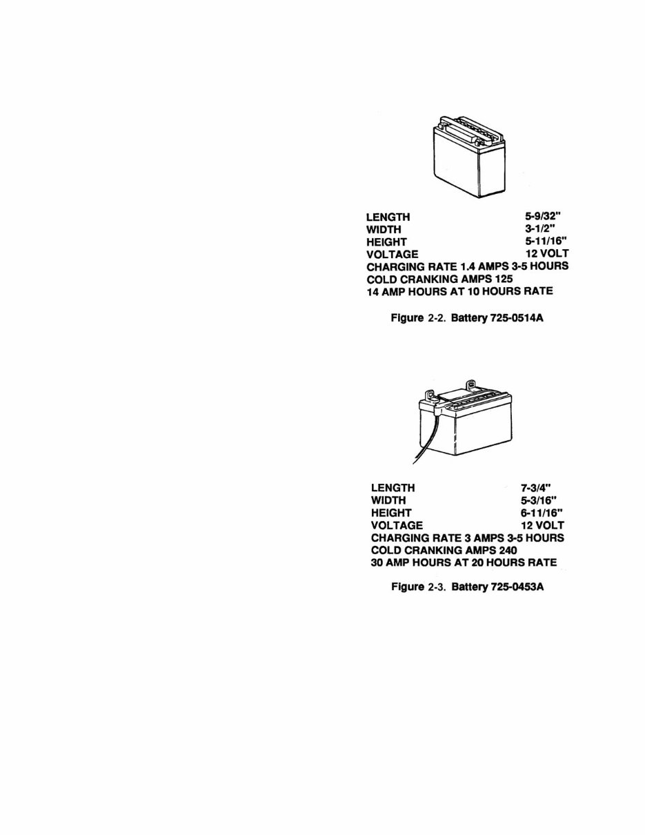
1. Battery 725-0514A (Figure 2-2) is replaced by
725-1633. These batteries are used on riders
and are the same size with the same cold
cranking amps. The number was changed due
to shipping regulations which would not allow
acid packs to be shipped with batteries. Acid
packs can be obtained by ordering part num-
ber 725-1637; however, we suggest dealer
obtain acid locally. Battery caps, part number
725-0691, can also be ordered separately.
2. Battery 725-0453A (Figure 2-3) is shipped with
no acid. Acid can be obtained by ordering part
number 725-1637, but it is suggested acid be
purchased locally. Battery caps can also be
purchased separately by ordering part number
725-0690. Battery 725-0453A was used on
1989 and prior 700 and 800 series tractors.
This battery is currently used in the 900 series
tractor.
3. Battery 725-1105 which was supplied in 1987
is no longer available. Use kit number 753-
0459 as a replacement. The kit includes a bat-
tery, cover and adapting clip. The larger termi-
nal end goes on the negative side of the
battery. The adapting clip also goes on the
negative side. The electric start unit uses a 7
amp fuse system
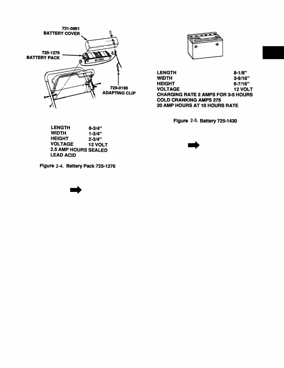
4. Battery pack 725-1276 (Figure 2-4) is installed
in electric lawn mowers.
BATTERIES AND CHARGING SYSTEMS
For Parts Call 606-678-9623 or 606-561-4983
www.mymowerparts.com
2-3
2
NOTE
During shipment, the hot wire can vibrate off
the battery and the unit will not start. Take the
battery cover off, hook up the wire and charge
the battery.
5. Battery 725-1430 (Figure 2-5) is replaced by
725-1635. These batteries are the same size
with the same cold cranking amp. The number
was changed due to shipping regulations
which do not allow acid packs to be shipped
with batteries. Acid packs can be obtained by
ordering part number 725-1637; however, we
suggest dealers obtain acid locally.
NOTE
Batteries 725-1430 only contain a special
chemical sulfate stop that has been added to
reduce sulfate crystal deposits (which eventu-
ally prevent the battery from accepting a
charge). Sulfate stop is a white powder chemi-
cal that may be visible before the battery is
activated, but dissolved once electrolyte is
added. After charging the battery (with sulfate
stop added), the specific gravity of electrolyte
rises to 1.280 or above. On a 5 ball hydrome-
ter, it is acceptable to see the fifth ball float. If
the battery contains sulfate stop and has not
been in use for a long period of time, extended
recharging time is required.
For Parts Call 606-678-9623 or 606-561-4983
www.mymowerparts.com

2-4
2-7.2 BATTERIES SECTION 1996-1998
#725-0453 E
Battery Type U1-11L
Dry 380 CCA Cold Cranking Amps @ Zero Degrees
Group No. U1L
Voltage 12V
Size Top 5.18 x 7.7
Number of plates 66
Height 6.12 to top of post 7.16
Weight wet 20.6 lbs.
Electrolyte capacity 72 oz.
Previously this battery was 240 CCA and it has been
upgraded to 380 CCA which gives added cranking
power in cold weather. It is shipped dry and it is sug-
gested that the acid should be purchased locally. The
acid pack number as shown is #725-1670 but acid is
considered to be hazardous material, therefore when
shipped, charges will be excessive due to special han-
dling.
Battery #725-1704
Note! New Warning symbols
Battery Type U-1
Wet 125 CCA Cold Cranking Amps
All batteries are date coded
Replaced by #725-1707 C DRY 275 CCA Cold
Cranking Amps
Size 5.18 x 7.7
Height 6.12 with Post 7.29
Voltage 12 volts
The #725-1704 is a wet battery meaning that it is
shipped in the rider and it is hooked up with the positive
terminal connected and the negative terminal has a
plastic cover over it to protect from shorting out. The
purpose of this is to assist stores with fast product turn-
over and in this manner the unit is ready to operate in
the least amount of set-up time.
Battery #725-1705C
WET 150 CCA Cold Cranking Amps.
Battery Type U-1
All batteries are date coded
Replaced by #725-1707C DRY 275 CCA Cold
Cranking Amps.
Voltage 12V
The #725-1705C is a wet battery and it is the same as
stated above. If a failure occurs in warranty the #725-
1707C will be shipped.
Battery #725-1706
WET 270 CCA Cold Cranking Amps.
Battery Type U-1
Negative terminal covered with a plastic cover and
shipped with the positive cable connected.
Replaced by #725-1707C DRY 275 CCA Cold
Cranking Amp.
All batteries are date coded
Battery is non-serviceable
Voltage 12V
The #725-1706 is a wet battery and is shipped in the
tractor and is ready to go by just removing the plastic
cover on the negative terminal and connecting the neg-
ative cable to the negative terminal.
Battery #725-1707C
DRY 275 CCA Cold Cranking Amps.
Battery Type U-1 Flat Top
Size 5.19 x 7.72
Height 6.12 Including Post 7.30
Voltage 12V
Manifold Vented
Specifications for ’97-’98 will be the same except all will
be flat top style. The knobs will be flush with the top of
the battery.
YUASA - EXIDE makes the DRY, add acid type batter-
ies EAST PENN makes the WET non-serviceable type
battery.
WET batteries are anticipated to be used in 50% of
our production for fast moving product customers, all
batteries can not be shipped wet because they would
have a shorter shelf life than a dry battery.
For ’97-’98 little changes are anticipated. Dependability
over all styles will remain the same. Replacement bat-
teries will continue to be shipped without acid, and acid
must be obtained locally due to acid being a hazardous
material, therefore requires special handling when
shipped.
New for ’98 season batteries will be similar in size but
top will be flat with nothing sticking up except the posts.
Fill caps will be flush with the top of the battery.
For Parts Call 606-678-9623 or 606-561-4983
www.mymowerparts.com
2-5
2
Batteries must be properly maintained if you
want long-life, this remark is repeated over and
over.
1. Check the electrolyte and add only water.
2. Keep clean, excessive acid build up around
the terminals and top of battery will cause a
discharge and drain the battery.
3. Check cables and clamps and battery case for
obvious reasons of leakage as this could
cause damage to the painted surfaces, the
battery compartments and to the pulleys and
transmission.
4. Make sure of the routing of the vent tubes and
that it is not pinched and left to drip on pulleys,
etc.
5. Replace caps firmly, if one or two gets lost,
replace them as soon as possible, often they
can be obtained from old batteries.
6. Maintain a fully charged battery with a reading
by hydrometer showing 1.265.
2-7.3 Recently, a man well experienced in automo-
biles and lawn and garden equipment was
charging a battery in his automobile in the
garage for a long period of time and decided to
check on how it was progressing. He walked
into a partially dark garage, not thinking, and
leaned over the battery and flipped on this cig-
arette lighter. Well, you can guess what hap-
pened next. The electrolyte gas exploded,
which is hydrogen and oxygen. He was very
lucky to have glasses on as the top of the bat-
tery hit him in the face. He quickly remembered
to turn the hose on his face and wash off the
acid which was starting to burn and no damage
was done, but he was left quite shaken and
thankful that things worse didn’t take place.
Think about it. His glasses were broken and
bent tight to his eyes which helped protect his
eyes, which proves it is a good practice to
wear glasses when working with batteries.
2-8. BATTERY STARTING CIRCUITS.
2-8.1 Battery starting circuits consists of the following:
•Battery as a source of energy
•Starter solenoid switch to transfer high starting
current from battery to starter (starter relay)
•Key start switch or other switch to energize
the starter solenoid
•Starter. A series wound, low resistance, high
current draw direct current motor.
NOTE
Sometimes the circuit breaker kicks out and
will not allow the unit to crank. Check the diode
wires to see if they are crossed. Reverse the
diode wires if crossed.
2-9. BATTERY CHARGING SYSTEM.
2-9.1 There are four types of charging systems typi-
cally used on lawn and garden equipment.
•Single circuit—3 amp system with one diode
•Dual circuit—3 amp AC system that runs the
lights and a 3 amp DC circuit to charge battery
•Tri-circuit—5 amp two diode system
•Regulated 16 amp system
MTD mainly uses the dual circuit and regulated
systems.
2-9.2 Regulated systems are installed on units with
electric clutches. These are Briggs and Strat-
ton engines with a voltage regulator. Some of
the early units had an 8 amp circuit breaker in
the unit. This is a 16 amp unit and needs a 20
amp circuit breaker (part number 725-1382).
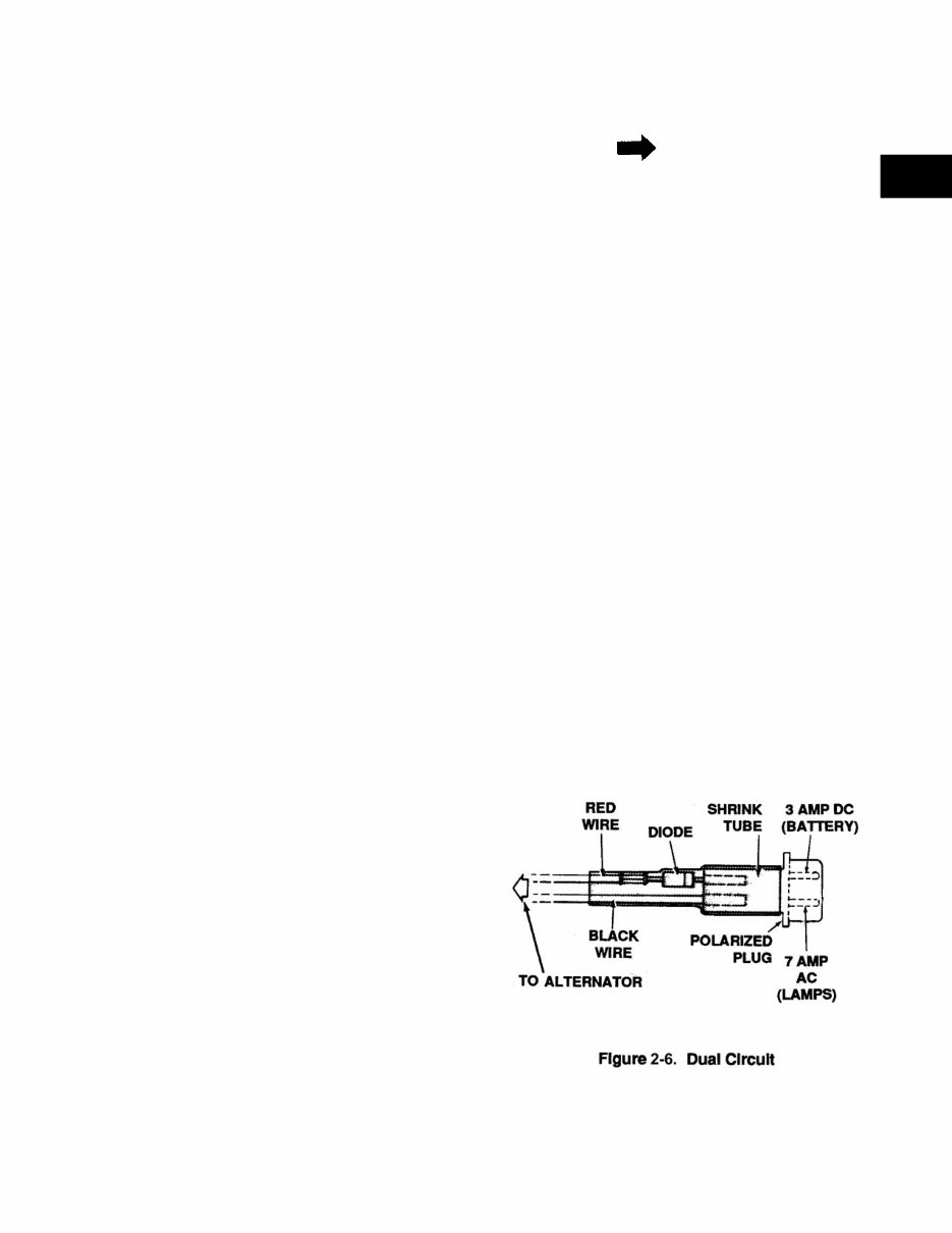
2-9.3 Dual Circuit (Engine Alternator) (Figure 2-6).
1. The charging system is an alternator located
under the flywheel. A half wave rectification
(single diode) is unregulated and rated at 3
amps at 3600 RPM.
For Parts Call 606-678-9623 or 606-561-4983
www.mymowerparts.com
You're Reading a Preview
What's Included?
Fast Download Speeds
Online & Offline Access
Access PDF Contents & Bookmarks
Full Search Facility
Print one or all pages of your manual
$52.99
Viewed 89 Times Today


Secure transaction
What's Included?
Fast Download Speeds
Online & Offline Access
Access PDF Contents & Bookmarks
Full Search Facility
Print one or all pages of your manual
$52.99
MTD REAR ENGINE RIDERS & LAWN TRACTORS SERVICE WORKSHOP REPAIR SHOP MANUAL
- GENERAL INFORMATION
- Safety Precautions
- Batteries And Charging Systems
- ELECTRICAL
- Safety Interlock Systems
- Safety Interlock Systems - Changes for 1991
- Electric Start System
- Recoil Start System
- Safety Interlock Systems Wiring Diagrams
- Troubleshooting Safety Interlock Systems
- Evaluating Electric Clutches
- BELTS AND DRIVE SYSTEM
- General
- Proper Storage of Belts
- Causes of V-Belt Problems
- V-Belt Problems with Rotary Tillers, Self-Propelled Mowers and Riding Mowers
- Belt Wear Due to Normal Life
- Pulley Alignment
- Idlers
- Maintenance Of Variable Speed Pulleys
- Four Wheel Steering
- Disassembly Of Four Wheel Steering
- Brake Adjustment for 600 and 700 Series
- HYDROSTATIC
- TRANSAXLES
- General
- Transaxle Changes For 1990, 1991, 1992 and 1997 Models
- Disassembly/Assembly of Transaxle
- Hydrostatic Transaxle
- Integrated Hydrostatic Transaxle
- TRANSAXLES
- LAWN TRACTORS
- 300 and 400 Series
- Rear Engine Riding Mowers 500 Series
- Transmatic LT 600A
- Hydrostatic Drive 700 Series
- YARD BUG
- Deck Leveling
- Brake Adjustment
- Blade Brake/PTO Adjustment
- Speed Control Pedal Adjustment
- Steering Adjustment
- Removal and Installation of Deck Belt
- Removal and Installation of Mowing Deck Assembly
- Removal and Replacement of the Drive Belts
- Transmission Removal and Installation
- Transmission Disassembly
- Transmission Reassembly
- Electrical
- AUTO DRIVE
- Leveling the Cutting Deck
- Deck Belt Removal and Installation
- Cutting Deck Removal
- Brake Adjustments
- Autodrive Pedal Adjustment
- Drive Belt Removal and Reinstallation
- Transmission Removal and Installation
- Transmission Disassembly and Reassembly
- Deck Belt Removal
- Hydrostatic Transmission Removal
- Steering Adjustments
- Electrical
- Autodrive/Autocruise
- MTD Z SERIES
- Transmission
- Neutral/Steering Adjustment
- Removal of ZTT Transmission
- Transmission Disassembly
- ZERO TURN TRACTORS
- 624 Zero Turn Tractor - The Revolution
- 46" Cutting Deck
- Cutting Deck Removal
- Lower Deck Belt Removal
- Servicing the IZT Drive Belt
- Servicing the IZT
- Adjustments to the IZT
- Parking Brake
- Under Dash Service Points1
- Dash Panel Removal
- Front Axle
- ATTACHMENTS
- Cutting Decks
- Improvements
- Grass Collectors
- Front Bumper
- Trapac
- 42" Dozer Blade


